Repair an Audiolab 8200CD

Hi, I recently purchased an audiolab 8200 CD, it works just fine. However, the led front panel is dim and hard to see unless I up close. So I am wondering if anyone familiar with this issue and what can I do to replace it.

By the way, the CD player doesn't come with a remote so I am also looking for a remote that I can buy on Amazon that works with it, assuming I can't find an audiolab remote.

Thanks in advance.

For Sale Audio Research Hi Def Power Amplifier Classic Model 150 Pair

For sale I have these units. One works fine I think the other is working but "goes" after a period of time before it goes.
They were great but they are physically big and I'm sick looking at them. They cost me about 6k a few years ago I think.
I left them in to get one fixed but they struggled due to parts etc.
Not sure if anyone on here is good at fixing bits up, if so I reckon these are pretty nice.
I just don't want them, they are heavy and I want something more minimal / compact.
I may have to dump them which seems a waste. As I said I am pretty sure one works no problems.
If someone want to to collect them for a reasonable price. You can test them first if you want.
I'm in Hoxton and have very flexible hours.
Just want rid.

An under-radar planar full range from Harman Kardon

This is used as roof surround speakers in GM BMW land rover and many more vehicles.
It is the speaker astounding me the most. Here is why. This unit is approximately palm size, for this size planar speaker I can find for sale on line it is usually an above mid tweeter but not able to reach 20k. and a very narrow high frequency spread angle, it is not be able to cover mid range or used as a tweeter. But this one I find out to deep as 100hz if you hear it near.
What is more amazing is that if u test it as a headphone it sounded just like audeze big planar, better than my moded fostex planar. from the deepest bass I have ever heard with any speaker to the highs I cannot hear the upper limit.
It is the only speaker I have heard be able to use as headphone and achieves hi-end performance. I think the speaker has the lowest distortions in the market for a full range. Of course u need many of them to really show the bass if used as a speaker because the x-linear is small.
With it, I came up an idea, a two way speaker with a 18-21 inch woofer and four this planar, crossover at 200-300hz to lower the distortions from coil speakers. I think this is not possible before.
IMG_20230214_231450.jpg
IMG_20230211_232303.jpg
  • Like
Reactions: JQS and studiotech

KT88SE - with EL34s

Hi all,

Could I just have a confirmation please?

I have the KT88SE build, as per Kegger/Blueglow schematic. Cathode Bias resistor is 500R set up for KT88.

The schematics state a number of other valves are drop in replacements, including the EL34.

Would I need to up the cathode resistor to 560R to ideally suit an EL34? Or, can use them with the 500R.

Having to do a repair which members here (rayma and others) have been very helpful and EL34's (being a half/third of the price of a KT88) are very appealing as funds are a little restricted to be honest.

Super easy phonostage using OPA2134 and 24V wall-wart

Here's an easy circuit that will make a good first project for beginners or anyone looking to quickly build a phonostage with good performance and easy to find parts.

This is a variant of a commercial design I did recently, simplified a little to serve as an example of how to use a DC switching supply properly on another forum.

At it's heart it uses the OPA2134 op-amp. This JFET input device is easy to obtain and well regarded, although the input noise isn't quite as low as we might ideally want it to be. Having said that the circuit performance a lot better than 98% of circuits you can find out there on the web. The JFET input draws almost zero bias current so there's no need for input decoupling which considerably simplifies the design.

The circuit is designed to work off of an external 24V double-insulated SMPS which can be easily obtained from multiple outlets. The rails are split into +-12V using resistors R4 and R5 in conjunction with zener diodes D1 and D2. Doing this means we don't have to worry about using bias networks and the grief and fiddliness they bring along. C8 and C9 provide additional smoothing and AC decoupling to improve the efficiency of the supply when under load with audio frequency supply currents from the opamp. C6 (X7R type, all the rest are NP0/C0G) should be connected as close to the op-amp as possible to prevent HF instability.

Starting from the input, resistor R1 provides the 47k load for the cartridge and capacitor C1 does double duty acting as the 100pF capacitive load from the pre-amp and also as an RF stop in conjunction to series resistor R2. These should be connected as close to the input connectors as possible with the shortest possible wiring to assure maximum possible attenuation of RFI.

The RIAA equalisation network shown is active and ensures excellent headroom compared to a lossy passive network. If you use 1% metal film resistors and hand select Cs 4, 14, 3, 13 to within 2% of the specified value you will get RIAA accuracy to 0.25dB which is considerably better than most commercial offerings! Capacitor C7 ensures the DC gain is unity as any op-amp offsets will be amplified by 60dB, either pushing the output up against the rail or seriously degrading available headroom.

In conjunction with R9, C5 applies the 20Hz IEC amendment and also DC decouples the output. This applies 7dB of cut at 10Hz where subsonic disturbances are likely to be, reducing intermodulation distortion further down the signal path. Valve amps really hate this. C5 should be a film capacitor and is easily obtained from sites such as Aliexpress for a low cost.

Finally resistor R3 provides enough isolation from the line at HF to keep the opamp stable and sets the output impedance to a respectable round 100 ohms.

So there it is, 4 different ceramic capacitor values, 6 different resistor values, 2 different electrolytic capacitor values and pretty decent performance. Quite elegant if I say so myself!

  • 7 VRMS output 50Hz to 20kHz into a 10k load
  • 40dB gain at 1kHz
  • THD < 0.002% 20Hz to 20kHz
  • SNR 75dB ref 5mV cartridge connected
  • RIAA accuracy 0.25dB (ref IEC amendment) 50Hz to 20kHz
  • Power consumption 200mW (no signal)
Enjoy!

EDIT: C6 should be X7R dielectric (it's what the 'unless stated' refers to)

Attachments

  • EasyPhono.png
    EasyPhono.png
    23.3 KB · Views: 577

FS: tubes

Sale:
GM-70 – 74 pcs.

5C3S (black plate) – 9 pcs.

5C4M – 47 pcs.

5C4M (metal base) – 4 pcs.

6E3P – 4 pcs.

6E5 – 2 pcs.

6J51P – 448 pcs.

6J52P – 46 pcs.

6N2P-EV – 268 pcs.

6N3P – 145 pcs.

6N3P-E – 870 pcs.

6N5S – 37 pcs.

6N6P – 1489 pcs.

6N7S – 394 pc.

6N8M – 1 pc.

6N8S – 436 pcs.

6N8S metal base – 52 pcs.

6N8S metal base hole plate – 31 pcs.

1578 meral base – 1 pc.

6N9M – 1 pc.

6N9C – 312 pcs.

6N9S MELZ metal base – 82 pcs.

6N9S Tantal metal base – 14 pcs.

6N13S – 74 pcs.

6N23P – 763 pcs.

6N23P-EV – 496 pcs.

6N24P – 413 pcs.

6N27P – 14 pcs.

6N33B – 12 pcs.

6P1P – 8 pcs.

6P1P-EV – 282 pcs.

6P3S – 279 pcs.

6P3S-E – 48 pcs.

6P6S – 172 pcs.

6P7S – 109 pcs.

6P13S – 237 pcs.

6P14P – 165 pcs.

6P14P-K – 48 pcs.

6P14P-EV – 259 pcs.

6P14P-ER – 50 pcs.

6P15P – 95 pcs.

6P15P-EV – 14 pcs.

6P18P – 298 pcs.

6P21S – 31 pcs.

6P36s – 50 pcs.

6P42S – 10 pcs.

6P43P-E – 180 pcs.

6P44S – 25 pcs.

6P45S – 124 pcs.

6S2S – 119 pcs.

6S2S metal base – 1 pc.

6S4S – 21 pcs.

6S5S – 46 pcs.

6S8S – 81 pcs.

6S18S – 1 pcs.

6S33S – 31 pcs.

6S33S Svetlana – 10 pcs.

6S33S-V – 104 pcs.

6S45P-E – 118 pcs.

6F1P – 123 pcs.

6F3P – 199 pcs.

6F4P – 230 pcs.

6F5P – 101 pcs.

6F6M1 – 6 pcs.

6F6S – 3 pcs.

6F12P – 77 pcs.

16F3P – 40 pcs.

30P1S – 1 pcs.

30C6S – 47 pcs.

Composite Gain Clamp

Like it says on the tin. I've been working on a Class D design and for the analog section for the feedback loop, I would like to make a gain clamp. I've been looking into different parts and I found two that I like, but am unsure (hence why I'm here). I'll more than likely be composting them to give the op amps more capability as well (be it slew rate, bandwidth, etc). The op amps in question are the AD8237 from ADI, and the INA849 from TI. Both have phenomenal specs, but also have their drawbacks (hence composite). The AD8237 really isn't designed for something like audio, but in tandem with an op amp with better slew rate, it could be very interesting. It says it's stable at all gains in the spec sheet. On the other hand, the INA849 just has very good overall noise figures, but more drift. I've also been considering the INA851, but that would mean a whole different set of design challenges. But hey, for all I know there may be an even better choice out there. Thoughts?

Curvilinear horn profile - Is it a real thing?

Hi Guys,

I've been looking at this Eighteen sound 12NCX750H (link below) coaxial driver and it comes with this horn, on the website its stated as a 'curvilinear profile LF cone'.
I'm a bit confused as this isn't a traditional horn profile I've come across in my research, e.g. exponential, oblate spheroid or le cleach.

Also I'm also thrown off by the circular profile (viewed from the front, I've attached a photo) transitioning into elliptical profile transitioning back into a circular profile. The ellipsis looks like a pinch in the throat. The ellipsis must drive the 50deg and 70deg coverage angles, also printed on the horn.

Let me know your thoughts, thanks.

Link: https://www.eighteensound.it/en/products/coaxial/12-0/8/12NCX750H

Attachments

  • 23_15_05_247_pndRp3Uy.png
    23_15_05_247_pndRp3Uy.png
    111.4 KB · Views: 86
  • horn.jpeg
    horn.jpeg
    620.2 KB · Views: 99

Parts Connexion

For years and years I swore by these guys. I was always amazed at how fast my stuff showed up. But the past year has been a totally different story. They say they have the parts in stock. I order them. Then a week or two later I realize I have not had an email saying its shipped. I email them and get " we are out of stock on " insert part here" and we will ship when we get it in." No notifying me. nothing... just late parts. I complained MULTIPLE times about communicating to me when this happens and have asked WHY DOES IT SAY IN STOCK IF IT ISN"T?? but I always get some bs answer and have to wait. I used to really like them. I don't know of anyone else except for that outfit in the uk. Very sad... Anyone know of any other parts houses that have cool capacitors and other overpriced boutique parts to toss away our paychecks on? I don't like having to leave them but enough is enough. Pretty sad..

Jeff

Seas A26RE4 in box measurement anyone?

I'm after an in box measurement of an A26RE4 - with known baffle dimensions please.

I am dubious of the Seas posted curve. I know Seas use an inbox measurement as stated in the conditions (28L) but unsure how they have determined the bass / lower midrange response. To me - it looks like they are showing an infinite baffle response and not the in box with baffle step response.

i.e. I'd expect this driver if nominally 88.5dB sensitive to show about 3 - 4 dB less output at 100Hz than the stated ~ 89dB in the attached image.

Any thoughts please?

Edit: If the A26 has built in "BSC" then thats good. I'm just concerned most of the kits I've seen assume 89dB sensitivity - about that of the woofer above the baffle step. So I'm wondering how these designs sound.... whether they are a bit thin.

1706821979211.png

KLE Innovations, anyone contacted them recently?

Hello,

I am in the market for replacing the RCA jacks on my gear. KLE has peaked my interest but i have not been able to find anything about their conductor composition. I contacted KLE through email a couple of times but have not received a reply. Has anyone heard from them recently?

My concerns are issues ive heard about oxidation and long term integrity of the part.

Thank you🙂

350 kW valve amplifier from 1934

A couple of days ago, I stumbled upon this article:

"The WLW 500-kilowatt broadcast transmitter", Proceedings of the Institute of Radio Engineers volume 22, number 10, October 1934, pages 1151...1180.

The transmitter was amplitude-modulated by varying its supply voltage. A 350 kW audio amplifier was used for that. It consisted of two 175 kW amplifiers in parallel, so the show could go on with less modulation if one of them happened to break down.

The output stage of each of the two amplifiers had four valves type UV 862, a water-cooled valve of about 1.52 m (5 feet) height. The supply voltage was 11.8 kV. Each output transformer had a weight of 19 ton.

I read it via the IEEE site, but you can also find it here:

https://worldradiohistory.com/Archive-IRE/30s/IRE-1934-10.pdf

Fender Deluxe Reverb Silverface, no EQ on one channel

Hi guys.
I just received a Fender Deluxe Reverb (silverface, I guess it's a 65 or 68 original) for fixing the normal channel witch has volume but treble and bass do not work. When turning up the bass control, sound gets thin and weak.
I swapped tube #1 and #2, and result is the same: no EQ on normal channel, tremolo channel works fine with both tubes.
Any idea what might be going on with the normal channel?

Meridian 808 CD player --Help please....

Hi All

I have scored an old Meridian 808 Signature Reference CD player which is not working ( 1st type – no inputs on back allowing use like a preamp like on later models)

Dumpster dive find….. (the things some people junk – but then there may have been a good reason!)

Unsurprisingly it doesn’t totally work

Problems are as follows –

a)

Display not legible at all--- just a faint even green glow- and only after pushing one of the control buttons


b) Disk not reading- drive is a dsl710- which appears to have a reputation for poor reliability- I have replaced the laser with one from ebay – but no joy at all there – new ones seem to command lots of $ and may not have correct firmware….


What I have done :

I figure if I cant get it to read disks then the display issue may not be looked into…..so disk drive issues first.

The original drive is a DVD Rom-IDE connector type


I installed a generic IDE DVD RW drive—yes it responds to all buttons on front panel😊

It has audio output😊

Cd output is on both RCA and XLR sockets

CD audio output has scratchy sounds -0 whether it be music or constant signal tones – I have uploaded sample of the noise it makes)

Interestingly I inserted the DVD “Hell Freezes over” by the Eagles

Audio output from that dvd seems fine – no scratchy sounds!

I have reseated connectors on the drive


Any ideas to fix the audio problem and possibly move on to the display ?????


Any suggestions or comments gratefully received

Many thanks in advance

George

Attachments

Eidetic GB-1b Power amp help

Hi all, I wrote in about a month or so back looking for any information on the Eidetic GB-1b power amplifier, I know Greg Ball seems to be out of the mainstream action at the moment (unless I'm quite wrong!), but I could really do with a full circuit diagram and voltage adjustment info if possible. I have picked up an amp recently that has very high DC on both outputs .. well, I consider 300mV+ on the LC very high and a bit less on the RC. Looks like one of the output trannies has got a bit hot on the board (LC). I will probably replace all caps on the boards, one or two look like they've taken a bit of a beating over the years, the mains switch has been replaced with an el cheap job that's too small for the cutout and I have no idea whether the plug on the back is pulled out for 1-2 ohms and left in for 6-8 ohms or what. No instructions for adjusting DC or bias and those I'd really like if possible.
Anyone got any ideas please? Any help from previous owners would be much appreciated! Thank you.

Brand New Super AKSA - the SAKSA 85!

Hi Folks,
Today I fired up my brand new SAKSA, the next generation of the Aspen range! This amp has:
1. Heritage from the original AKSA 55, particularly the midrange and top end.
2. VAS stage enhanced from the original NAKSA 80.
3. Improved output drive system from the Maya.
4. Footprint from the NAKSA 80, identical to the pinout and heatsink.
5. Lender VAS drive with shunt compensation and phase lead - no lag comp.
6. Nested feedback like all my recent amps deliverying low global feedback - 29dB.
7. Strengthened output stage over the NAKSA 80, all complementary mosfets rated at 280W and 38A.
8. Snubbers on all gates to guard against self-oscillation, the bane of mosfets.
9. Clip indicator (RED!!!)
10. Same price as the NAKSA 80, $AUD930 including 300x75mm 0.37C/W heatsink.

Technical:
The amp has a THD of 0.06% at 12.5W, 1KHz into 8R, 97% being H2 and H4
All fuses are 10A. Slew rate is 15V/us, 1dB down at 12Hz and 150KHz (LP filter in place).
Subjectives:
Very strong bass and midrange. Top end utterly clean. Lots of speed, PRAT, and engagement. You close your eyes, and tap your foot. Very spatial, you can 'see' the instruments in place front to back on a large orchestra. HUGE soundstage and very low intermodulation on choir and orchestra.

This will last as long as the original AKSA. This is a superior amp with a huge of careful engineering and psychoacoustic detective in it. It is knocking on the door of the Maya, and that is a watershed of my amp designs.

I have my first batch and ready to roll for despatch. Wait for a bit on an old, slow guy when I respond, but I'm still the same old Hugh of yore and I will get through all of it over time........!

A very happy day for me, this year both new ground breaking designs have come to life!

Ciao,

Hugh

Attachments

  • SAKSA2.jpg
    SAKSA2.jpg
    456.2 KB · Views: 4,053
  • SAKSA3.jpg
    SAKSA3.jpg
    471.4 KB · Views: 3,848
  • Like
Reactions: peter19500

Should an RCA get hot?

I experience something odd and am somewhat concerned. I recently purchased second hand:
  • A topping MX3
  • A pioneer S-21W subwoofer
  • 2 Q acoustics 3020 speakers
I connected everything up twice with no obvious issues. The audio source was an RCA cable that has an Apple lightning jack at the opposite end.

I had to move the set up, then connected things back up and couldn’t hear anything. I messed around with it for a while, then noticed the lightning end of the RCA was incredibly hot.

I took everything apart then realised I’d mixed up one speaker’s pos/neg input on the amp. I fixed this, but still nothing. Tried a different RCA and all good.

So the issue is somewhat fixed but I’m worried about what broke the cable and made it so warm. I don’t think the speaker wire mix up should do that. Could the amp be sending a current down the RCA? Is it too risky to use?

Thanks!!

Counterpoint DA-11a transport died

Hi All,

Was watching TV last night when I heard a weird noise and then the lights on my counterpoint transport just went out.

No smoke, no flames - but the strong acrid smell of a capacitor taking a dump. When something like this happens, does it normally take a few downstream components like resistors, etc with it - or could it be a simple cap replacement and move on?

The unit is old, and a full re-cap probably wouldn’t be a bad idea. These generally aren’t exotic caps, so material cost would be pretty low.

I don’t have a trusted tech nearby and wondering if a simple DIY recap is worthwhile/advisable vs finding a tech to take a look..?

Note:
I’m handy with a soldering iron, but limited to pretty much “paint by numbers” when it comes to design and real technical knowledge.

I’ve rebuilt Dynaco’s, Heathkits, etc., but had a tech friend test and double check my work before plugging it in. So I’m very comfortable w/replacing parts, just not comfortable poking around live voltages - lol.

Thanks guys!
IMG_4945.jpeg

Planar Tweeter Issues… Always...

Alright, I'm throwing in the towel and asking ya'll.
Planar tweeters.png
What is the deal with planar tweeters. I know the supposed to be superior because they can go higher but no matter what I do in Xsim they always behave badly. I usually can run one large woofer, a mid to fill in the mid range, and a tweeter up top to get a fully flat range. Every time I try to design something with a planar tweeter the high end goes nuts.

Am I doing something wrong?

Simulate OPT SX-11 at low frequency

Hello, I am simulating the response of a Monolith Magnetics SX-11 (Rpri = 330Ohm, Lp = 24H, Wingding ratio = 25.25) at low frequency.

For the simulation I assumed the source is a 300B tube with 800Ohm Rplate, and the load is a loudspeaker with Re 6.5Ohm a resonance peak at Fs=40Hz,
I modelled the 300B output with a current generator in parallel to Rplate, and the loudspeaker with at RLC equivalent circuit.
For the simulation, I only considered Rpri and Lp of the transformer since the effect of the stray capacitance is negligible at the low frequencies,

1706605258382.png


First I ran an impedance/frequency simulation of the speaker to verify that the model was correct and I got a 90KOhm peak at 40Hz seen from the primary of the transformer (equivalent to a 144Ohm peak on the secondary), which is what I was expecting.
1706605723121.png


Then I simulated the frequency response of Vload/Vplate and this is where things look to good to be true: the simulation shows large +.6dB peak centered around Fs=40Hz (see image below) which pushes the -3dB frequency below 3Hz.
1706606205983.png


Of course, the simulation doesn't take into account of the saturation of the core, but this still looks too good to be realistic.
Am I missing something in the simulation or doing something incorrectly?


BTW.. if I replace the loudspeaker model with a resistor R=5K I get still a very low -3dB frequency at lower then 3Hz.
1706607402614.png

Attachments

  • 1706605981047.png
    1706605981047.png
    5 KB · Views: 75

Re-biasing Forte Model 6 deeper into class A

Hi All,

I'm helping a friend Refurbish and re-bias his Forte model 6 amp. The amp measured about +/- 67 VDC at the filter caps and the voltage drop at most emitter resistors I could reach was around 50 mV. The amp sounded pretty good and the heatsinks got warm but not too hot at all. Nice, detailed sound, but a little weak in the bass and a little crispy/crunchy in the highs.

A common path with these amps seems to be lowering the supply voltage and increasing the bias while remaining within the heat dissipation capabilities of the heat sinks to operate further into class A. This sounded enticing to my friend to try, so let's go for it!

Poking around the amp I discovered that the power transformer had some specs on the side that I could sort of make out. The red colored secondaries (the ones that were initially connected) were 48-0-48 VAC and I saw that there was also a set of unused green colored secondaries at 29.5-0.29.5 VAC. This seemed like an obvious choice so I hooked up the other pair of secondaries the same way as the original configuration and now I had about 41 VDC unloaded at the filter caps. Great, I think, so I go about setting the bias and set it up to about 75 mV on each channel at first to be conservative. I found that after the voltage changes, I now had some significant DC offset at the outputs so I used the other set of trimmers to zero this out (I assumed these trimmers were for DC offset and they did change it but I'm wondering if they are changing something else). Everything looked good and just letting the amp idle for some time, the heatsinks got hotter than the original configuration but not so hot that I couldn't permanently leave my hands on them.

I figured I was ready to fire the amp up on my current limiter and then listen to some music. No problems or shorts and now onto the music. I noticed something different right away in that I had to crank my preamp much higher to get the same amount of volume. Also the sound was Ok but not great or necessarily better than before. This is confusing because most people rag on the model 6 and praise the model 4. I've also heard my friend's model 6 converted to model 4 specs and thought it sounded incredible. On this amp, the sound was now less dynamic and more laid back than the original configuration and a touch smoother but it didn't grab me as that great in any way. Of course this was a different time, speakers, room, etc...so I'm aware of the limitations of psychoacoustic memory but I do trust my ears.

So, at this point, I'm a bit confused as everything seems to check out upon a cursory inspection as the voltage and bias are where I would expect them to be with the changes I made. Maybe there is a new issue with my preamp but that seems highly unlikely. By lowering the voltages by a little over 50%, is it expected that the input sensitivity would drop significantly? This doesn't make sense to me. Of course headroom and power output before clipping would drop but the volume that I was playing music at should have been nowhere near that. Is it possible i made some mistake I'm not aware of? Should I try with an even higher bias?

Lastly, I don't understand how these amps supposedly go from being 200 watt AB amps to 50 watt Class A amps. Where I'm at currently, I think I could maybe go up to at most 100 mV across the 0.47 ohm emitter resistors before the heatsinks were too hot so this should be about 200 mA per device, correct? If we assume that class A requires quiescent current and output current into the load to be equal, this bias level appears to be nowhere close to 50 WPC class A.

Thanks for any help!

SN16861 SN16862 data

Hello. I am new to this website and I hope someone can help me. I am repairing my Quad 44 preamp. It uses SN16861 and SN16862 switching ICs in the input selection circuit. My version of the 44 has two SN16861 and one 16862. I have sourced some new SN16861 and replaced those. I cannot source a SN16862. I know that the main difference between the two ICs is that the SN16861 has 4 inputs and SN16861 has only 2. Quad used three SN16861 in later versions of the 44 but I cannot find out whether I can simply install an SN16861 in place of the SN16862, i.e. whether they are pin for pin compatible.
Any help would be greatly appreciated.

Can I simply increase the voltage rails to +/- 32VDC to get more power into my 5 ohm speakers

Hi,
I built the Pass F6 a few years ago, and love it. I have the channels biased at 1.6vdc each, rails are +/- 24vdc, and it sounds very 3D, warm, and class A. I would love to have a little more power for my 5 ohm, Infinity sattelites. I am biamping from 140hz down into a pair of Rythmic subwoofers. I am looking over the F5 Turbo article by Pass, and see where he says that simply increasing the rail voltages from +/-24vdc to +/-32 vdc, on the F5, will give you double the peak power. I have most of the parts ,less chassis, to build an F5, but I am wondering if I can simply swap out my power transformer on my F6 to one with dual 24vac secondarys similar to the F5 , and increase the power. Anyone know what kind of wattage increase I can get by doing this for my 5 ohm speakers?
Thanks in advance,
mg16

Absolute Limits of OB vs Reflex vs Sealed vs TL vs Horn: HEURISTICS

I’d like to introduce some new, partly-developed speaker performance metrics I’ve been chewing on. These could be developed much further with the help of others. I’d love to hear your ideas.

Box types suffer from stereotypes. “Sealed boxes are inefficient” or “Transmission lines are oversized” or “Dipoles have no bass” or “Horn speakers have terrible frequency response.” And while those reputations hint at certain truths, great designs defy the stereotypes. It always comes down to quality of implementation. The less-common box types are often made with drivers that were optimized for some other box type, and sometimes fall far short of their potential.

Each box type just applies different constraints to the same fundamental limits. The laws of physics still apply.

So for example sealed and reflex designs operate on 3D volume. TLs and horns operate on length and area. Open Baffles have the interesting quality of operating on 2D surface area.

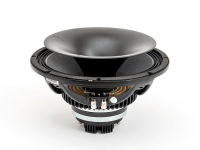
Trading off 2D surface area against 3D volume is super interesting. It means if you have a woofer with low depth (such as the Stereo Integrity BM-11) you can create a large speaker with low F3 that still takes up very little 3D volume in liters; and has a very slim profile.

This could be reduced to a “Hoffman’s Iron Law-Like” formula, a metric like:

Acoustic watts per liter per Hz (3D box)
vs
Acoustic watts per square meter per Hz (2D Open Baffle)


[these metrics are my very intuitive guesses; once properly formalized they will look somewhat different]

and these could be further refined into practical engineering heuristics, like

dB per liter per Hz (3D)
vs
dB per liter per Hz (2D)


and further

dB per kilogram per Hz (3D)
vs
dB per kilogram per Hz (2D)


and

dB Hz per dollar (3D)
vs
dB Hz per dollar (2D)


and

dB Hz per watt (3D)
vs
dB Hz per watt (2D)


This helps us formulate some interesting new questions.

If you define the problem as WEIGHT / MASS per unit of acoustical output, OB’s can become extremely attractive under certain circumstances. The stereotype is that they are expensive but commercially OBs could be quite economical.

So for example 3D volume-based box speakers always have to have 6 sides.

But 2D surface area-based speakers (dipoles) can have as few as 1 side.


A “lambda” shaped U-frame has a front panel, triangular wings, no top, no bottom, and no back. This delivers CONSIDERABLE savings in weight and shipping cost (which is a huge contributor to the price of a commercial speaker system!!!)

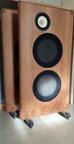
It’s a lot less lumber as well. You spend more on drivers and less on wood and labor for construction. The 
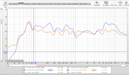
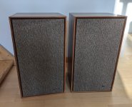
Walnut Dipoles can hold their own in SPL bass output very well with similarly sized speakers of other box types. Small but mighty.

Economically it is often less expensive to buy a 15” or 18” woofer and mount it on a big slab of live edge wood, than to buy an 8” or 10” woofer, build a 3D box and cover it with veneer. (And put a port in it.)

Plus the result is a lot closer to a piece of furniture that people will still enjoy 40 years in the future, than a conventional box where the veneer gets nicked and scratched.

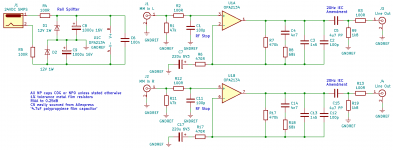
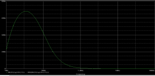
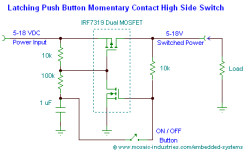
Then there is the difference between voltage sensitivity and efficiency. I ran simulations and showed actual examples of a “passive bass boost” circuit which boosts dipole bass 4-7dB. It does so by essentially converting voltage into current. The speaker with LC circuit has an impedance dip at its low frequency cutoff instead of a peak. It’s not technically more efficient, but it draws more current from the amps so it’s more sensitive in the low bass. Sometimes it’s easier and less expensive than DSP.

I took an acoustics class in college and I could probably work out how to formalize these heuristics if I put a lot of hours into it… but why not make this a group project?

We have some VERY smart people who hang out in this forum, some of whom have extensive modeling, mathematics and acoustics background.

New models and heuristics like this will shed light on what precise kinds of tradeoffs are optimal for each box type. This will lead to better drivers and better-engineered systems.

What do you think?

@Juhazi @CharlieLaub @nc535 @gedlee @Studley @Balthazarp

Walkie Talkie mixer Help

Hello!

I am trying to get my head around building a small belt-worn (if possible) box that would make it possible for me to mix the audio signals from 4 Walkie Talkie Radios.
I would like to add the following features:
  • 4 potentiometers controlling mix level
  • 4 potentiometers controlling pan
  • 4 buttons shorting the PTT function of each walkie
  • 1 button shorting all PTT functions of all walkies
  • 1 mic being sent to all walkies
The walkies have 2 different plugs but they both have pinouts similar to this;

motorola-gcai-mini-pin-configuration.jpg


I have general soldering / electronics and programming skills and was thinking to use something based of this:

4-channel-audio-mixer-LM3900-ic.png


The goal hers is functionality > Audio quality.

Any and all help is very much appreciated 🙂

Krell FPB 300CX transistors emitter resistors

Hi,

My name is Jose Oliveira and I live in Portugal.

I have plans to change the transistor emitter ceramic resistors on the output board of my Krell 300CX, replacing them with Mundorf MOX 5W resistors.
My problem is that, in some of the transistors, the Krell amp is using 0.2ohm resistors and Mundorf MOX does not have 0.2ohm but only 0.22ohm on the list.
I would like to have your opinion if, in case I do it, you think I can face problems or not.

Anyone with experience on refurbish of Krell FPB amps?
I replaced all the electrolitic caps and all IC´s with very good impact, is there anything else anyone suggest I should try ?
Thank you very much in advance for your time and help.

Kind regards ...... JOliveira

Attachments

  • Krell Output Board_all.JPG
    Krell Output Board_all.JPG
    160.7 KB · Views: 245
  • Krell Output Board_1.JPG
    Krell Output Board_1.JPG
    102.8 KB · Views: 228
  • Krell Output Board_1b.JPG
    Krell Output Board_1b.JPG
    117.5 KB · Views: 216

50W Stereo Vacuum Tube Amp with Hi Performance OPTs - $750

This tube power amp is a great performer at a decent price.

Freed made some really excellent power transformers, now quite rare. I've attached a .pdf spec sheet of their KA-10 power amp XFMR - incredibly linear.

This Williamson power amplifier uses a pair of Freed KA-10 OPTs and Russian 6P3S-E output tubes (6L6GC). . I have attached schematics of the power supply as well as the amplifier stage.

The amp incorporates Dave Gillespie's EFB™ bias circuit, to maximize performance and tube life. Better than that, this amp was tested by the Guru himself.

Features include individual bias and balance pots for the output tubes, so a perfectly matched pair / quad (while advisable) isn't absolutely necessary. There are test probe sockets on the top to make checking the cathode current of each power tube easy. All of the labels are laser-etched for durability. Among the pics is one showing the rear connections of the amp, and the vented bottom panel.

The amp produces a measured 25W RMS/channel with a 1.0V input, with frequency response flat to 20 kHz, down 1.0 db at 50 kHz.

I'm thinning the herd, and so I am selling this at a fraction of what all of the time & materials cost and / or are worth.

Price drop to $750 (plus shipping, if applicable).

Jon

Attachments

  • Freed Front.jpg
    Freed Front.jpg
    287.6 KB · Views: 190
  • Freed rear.jpeg
    Freed rear.jpeg
    237.2 KB · Views: 193
  • Freed Top.jpg
    Freed Top.jpg
    416.3 KB · Views: 184
  • Freed Power Supply.png
    Freed Power Supply.png
    142.2 KB · Views: 194
  • Freed Power Amp section.png
    Freed Power Amp section.png
    146.6 KB · Views: 178
  • Freed xfmr1.png
    Freed xfmr1.png
    272.5 KB · Views: 202

C1647 & C1312 transistor replacements?

I have an Akai R2R deck - 4000ds MkII. In the schematic on the service manual it is showing a pair of ICs on the preamp board, but mine has no ICs, but instead two 1312 and one 1647 transistor on each record channel, and one 1312 and one 1647 on each playback channel.

What can I use to replace these 1647 transistors? They look like this, which is not the same as the big power ones when I google it so I'm a little confused:

IMG_20240130_123536.jpg


It seems I can use 1845 for the 1312. Should I just use 1845s flipped backwards?

I replaced the eight c458 transistors with 1845 already.

O.H. Schade (1938) meets mosFET

Lately there has been quite a few threads covering the work of OH Schade 1938, http://www.clarisonus.com/Archives/TubeTheory/Schade 1938 Beam Power Tubes.pdf . He showed how a tetrode could get triode characteristics with the help of what he called "inverse-voltage feedback". While working as a triode the efficiency of the tetrode was still kept.

On the left is a tube SE in accordance to his suggestion. It has the same output impedance and distortion characteristics as if it had been triode-strapped but twice the output power! On the right the output device is substituted by a common MOSFET that according to Schades suggestion is feedbacked ca 20dB.

Seeing any similarity with a Zen😎?

By the use of an IT there is a better chance of getting much better HF-bandwith. The example sims with a -3dB point in the region of 100kHz.

Attachments

  • schade.png
    schade.png
    71.3 KB · Views: 2,810

FOR SALE: A pair heavy duty Collins Reactor Choke 6 Henry, 300 mA, tests 2500 DC Volt

For Sale a Pair Collins 6 Henry 300 mA DC Voltage, tests 2500 V DC , 40 Ohms Chokes.

Those are in good condition and they are very heavy, high voltage chokes,
Because of their weight I WILL NOT Ship!
You must be able to pick it up in Toronto, Keele and Lawrence area.
I wanted to use those with my GM 70 DIY tube mono-block amp witch will never materialized.
I plan to relocate to EU due to difficult circumstances and disability.
I sell most of my stuff, latter will sell the tubes (some matched copper tubes and some matched carbon tubes) and tube sockets also.
Please do not ask to ship, I can not.
Payment only cash at pick up. $150 for the pair!
The asked price is FIRM, No trade.

thanks for the interests.
Gabor

Attachments

  • IMG_0002.JPG
    IMG_0002.JPG
    260.5 KB · Views: 76
  • IMG_0003.JPG
    IMG_0003.JPG
    182.9 KB · Views: 62
  • IMG_0005.JPG
    IMG_0005.JPG
    200.6 KB · Views: 64
  • IMG_0004.JPG
    IMG_0004.JPG
    190.8 KB · Views: 76

Hornresp confusion

I spent half an hour trying to find out what Max SPL is actually showing. First I assumed it shows the output at a certain wattage and colors the response graph red when you exceed xmax. But when I enter 1watt in the max SPL tool the response doesn't at all correspond to what i initially modelled.

My initial modeling output:

Screenshot 2024-01-30 094332.png


Max SPL at 1 watt...........why doesn't it resemble the previous graph???? :

Screenshot 2024-01-30 094412.png


Also there always seems to be a huge peak around 30Hz in the max spl graph whatever enclosure type I model while the modelled response graph is flat....

Tweeter add on consideration

Hi

I've completed recently my two way open baffle speakers (ones that everyone seems to do now), consisting of a single 4 inch wideband and two 12 inch woofers.
Crossed over at 300 Hz, with an active electronic crossover of 24 dB/Oct I've made.

Dsp is applied threw a convolution filter at a streamers end (volumio) and a final fr spans from around 40 Hz, to over 10 kHz, on axis at least (the orange FR is with dsp, the blue one without).

Although results are very good, I'm curious if adding a tweeter to the system would bring significant improvements.

Possible solution that I can think of:

1. Tweeter with a waveguide placed close to the wideband, crossed at around 3-4 kHz.
Waveguides are relatively wide and I can't really put the tweeter right next to the wideband. The lobing might be even more pronounced, as wideband-tweeter would be positioned horizontally.
Back wave of the speaker would be basically cut above 3 kHz.

2. Tweeter with a significantly higher crossover point (10kHz or so), pointing upwards. Never heard anything similar.

Any thoughts?

Cheers,
Stefan

Attachments

  • 20240105_180140.jpg
    20240105_180140.jpg
    169.3 KB · Views: 108
  • 20240105_111733.jpg
    20240105_111733.jpg
    271.9 KB · Views: 142
  • sonido_rew.png
    sonido_rew.png
    70.1 KB · Views: 107
  • Like
Reactions: NIXIE62 and frangus

For Sale APEX FX-8 Bimo mod partial kit (PCBs + active components only).

As the title says I want to sell this item, which includes a pair of PCBs and complete active components to build a stereo amp.
You just need the resistors and capacitors to make this a complete kit.

Here's what's included in the package:
  • a pair of PCBs
  • 2 pairs of genuine 2SK1058/2SJ162
  • 2 pairs of 2SC3503/2SA1381 (hFE matched*)
  • 2 pairs of 2SC1845E (hFE matched*)
  • 2 pairs of 2N5401/2N5551
  • 2 pcs red led
  • 2 pcs 1N4148

This is a simple DIY amp project (only requires 8 transistors per mono) that sounds great.

* I matched the transistors using only a DMM, not sure if that's gonna be useful or not.

Asking for $60 (Shipping & PP fees included)

PM Me if interested

Attachments

  • Screenshot_20240122-134045~2.png
    Screenshot_20240122-134045~2.png
    380.3 KB · Views: 134
  • Screenshot_20240122-134030~3.png
    Screenshot_20240122-134030~3.png
    667.1 KB · Views: 138
  • Screenshot_20240106-142051~2.png
    Screenshot_20240106-142051~2.png
    86.1 KB · Views: 143

Diode reverse recovery time at very small currents

Dear all,

For a while I have been thinking about using the "diode matrix rom" to get "binary to thermometer code" converter. And I got some (lovely) ideas to segment some 2 bit pieces in such a way that 6 bits or so unary segmented DACs might not be humanly impossible anymore. I will share these ideas soon.

But for now the thing is when I look at the specs of some fast switching small signal Schottky diodes (such as BAT54, SD103AW...) the reverse recovery time is almost always given for I_F = 10 mA and R_L = 100 Ohms.

I have reasons to employ some large series resistors. But the difficulty is, smaller I_F would yield faster recovery but larger resistor would slow down the "discharge" of the junction. So here is the question: Pick a diode from above, connect it in series with a 20 - 50 k resistor. And then:

1) When you forward bias this series combination with 5 volts, how quickly would you expect the diode to turn on?

2) When you switch the polarity, what could be a typical reverse recovery time?

No precision is needed here but I would like to get some ballpark figures like 10's of or 100's of ns or some micro seconds... Any ideas??

A stuffing question

A pair of speakers followed me home from a pawnshop last weekend. I won't go into details just yet because this post is only about the unusual way they are stuffed.
I've never encountered speakers with blocks of open-cell foam loosely installed. Is this a thing?

This is just what's found in the midrange/tweeter enclosure. I don't know the nature of the bass section as I would have to disassemble it more than I'm willing to during the first week ;-)

IMG_20240129_184333.jpg

opposing speaker pair configuration

HI .
some time ago I read, I don't know where, about identical speakers (woofer or subwoofer) facing each other, cone against cone. one pair for each piece of furniture.
Now I would like to read further but not knowing what this configuration is called, I can't find what I'm looking for.
It's similar to push pull but unlike the latter, what I mean has the cones arranged on planes set at 45 degrees.
the only image found, which comes close to what I'm writing about, in order to understand what I mean, is the attached one.
can you tell me what it is?
Thank you .

push pull.jpg

Looking to buy: Eidetic GB-1a/2b Preamplifier

I have a treasure in the form of a restored and slightly upgraded Eidetic Gb-1b power amplifier and I'd really love to have the matching GB-1a preamp.
Since I live on the Sunshine Coast in Australia, it would make sense to see if someone here that lives in OZ has one or knows of someone who does.
I figure even a GB-2a preamp would do too. I don't mind if it's not mint, as long as the screen printing on the front is still all readable and that the unit runs well, or needs just a little tickle up. Many thanks for any replies.

Crown CE 1000

Hi guys. A friend retired PA guy give me for free crown ce1000.The amp have fault on channel 1 the clip led stays on.Check everything under main board found nothing broken.All small capacitors replaced except the two main filter caps.I suspect one of the upper board 8-4 pins smd chips 339 - 33078 - 33079.The amp was very dirty inside must be running on smoke area the main board covered with brown mix from sticky dust after the front face platte where the air comes in.I have clean carefully the components and the smd pins.Fire on with two 40w in series dim lamp and no difference.The dim lamp stays just a little on (no short) and after that i run the amp direct on 230 mains again no difference stays on clip channel one.Any hint what check next?

BG neo-8 drivers, neo-3 drivers, Carver Amazing Speaker 12" drivers/30" ribbon drivers, Magnapan Tympani IVa's, Gallo Nucleus Solo... For Sale

I have the following available:

BG Neo-8 planar drivers, slightly used, quantity 20. $1200 for all.

BG Neo-3 tweeter, new, quantity 2. $125 for both. SOLD

Carver Amazing Speakers 12" bass drivers, refoamed, quantity 8, $400 for all.

Carver Amazing Speakers 30" ribbon tweaters. 4 working, 4 not working. $800 for all.

Gallo Nucleus Solo speakers with stands. Silver color. Excellent working order, a few dings. $SOLD

Magnepan Tympani IVa's. White. Factory refurbed about 5 years ago, then put in storage. I unpacked them 1 year ago and have been using them. Just too big for my space. Excellent condition. $SOLD.

Reasonable offers considered. Buyer pays shipping. PM with questions. Located in south western Wisconsin.

For Sale $400 Elekit TU-8500 preamp, tubes, upgraded phono stage caps, everything works

$400 k+ s/h. Not accepting lower offers at this time.

I assembled this pre-amp from Elekit. The Japanese company had some of the best instructions I've seen in this space. I upgraded several of the capacitors having to do with the phono preamplifier. I also upgraded the tubes. Original tubes come with this sale. There are four RCA inputs, 1-4, no special markings on any of them. #4 is the phono. You can switch between MC/MM, there's also something called "flat amp gain" that's especially for blowing up amps. Ask me how I know 😉

It's a fabulous little pre-amp, and many more years of life left in her. Enjoy!

For a longer review, look for "TU-8500 wall of sound review." I bought this unassembled kit from tubedepot.com, it currently retails for $595.

https://www.ebay.com/itm/126306826264

Attachments

  • IMG_6706.JPG
    IMG_6706.JPG
    488.2 KB · Views: 99
  • IMG_6707.JPG
    IMG_6707.JPG
    554.3 KB · Views: 99
  • IMG_6708.JPG
    IMG_6708.JPG
    592.2 KB · Views: 96
  • IMG_6709.JPG
    IMG_6709.JPG
    639.5 KB · Views: 102
  • IMG_6710.JPG
    IMG_6710.JPG
    397.1 KB · Views: 116
  • IMG_6711.JPG
    IMG_6711.JPG
    614 KB · Views: 114
  • IMG_6712.JPG
    IMG_6712.JPG
    483.6 KB · Views: 114
  • IMG_6713.JPG
    IMG_6713.JPG
    482 KB · Views: 106

Is Ilag™ the stickiest material ever produced?

I have been an early adopter of ceramic non-stick pans; probably ~20 years ago or so. At the time, it was a small revolution: good non-stick properties combined with mechanical and thermal ruggedness, an ideal combination.
After a few years, the properties degraded, and they became stickier than regular (non-PTFE) pans.
I thought that the technology would improve with time, and that newer models would retain their properties for all their useful life. In a sense, that became true: they were lousy from the very start.
In-between, I have tried to preserve and save the pans I bought: I resorted to gentle hand-washing only, as the dish-washer degrades the coating, and I used them only for frying, with just some kind of oil or fat, never for deglazing or adding wet or acidic ingredients.
Nope: my latest, beautiful pearl-white Ilag pan stuck like hell from the very start, even though I take all the precautions required: I use a comfortable amount of grease, heat the pan at 180°C and carefully dry the meat or fish I fry, but everything I attempt to put in sticks instantly and very strongly. The only advantage is that I can use a metal utensil to unstick the food and scrape the pan.
Why such a failure?
As a comparison, PTFE pans seem to last almost forever when used properly. Of course, the coating process requires PFOAs and they are not as mechanically rugged as ceramic, but they are much more durable.
Newer ceramic coatings seem to originate exclusively from Ilag, and they are cr*p

Nakamichi PA-7 going into protection

I'm working on a Nakamichi PA-7 amplifier that was found by an acquaintance recently at a thrift store. When he first started using it, the left channel would go into protection after a few hours. I got it on my bench and started to take a look; the first thing I noticed was that the bias was extremely high on both channels, over 150mV before I powered it off. I was able to adjust the bias to the nominal 40mV, and the offset to the nominal 100mV. In this state, the amp draws about 2-2.5A, which seems comparable to what others have seen.

I gave the amp back and it's still tripping protection on the left channel. He swapped speaker leads and it still trips the left channel only. Oddly, I've never seen it happen in my workshop, but perhaps that's a difference in speaker loads.

This particular amp has the additional small protection PCB on each channel, which I understand was a later revision by Nakamichi. I did diode tests on the two transistors on each board, and all pin combos measure the same between the two channels. Similarly, the resistors, diodes, and capacitors on the PCBs also measure the same. One potential clue is that, with the amp powered on, when I probe the voltage across the top two pins that connect the protection PCB to the main PCB, it measures 86v on the right channel, but on the left channel it will trip the protection, the relay will open, the voltage will drop to about 2v, then it will rise after a few seconds to 86v, at which point the protection relay closes again. The two pins I'm probing attach to one lead of D109 and R152 on the main PCB.

Does anyone have suggestions for other things I could look at to diagnose this problem?

For Sale 2020 DIY Sony VFET p1 amp from diyaudio lottery

It is very sad for me to let this amp go, as it is a very special amp for a longterm diyaudio member. However, life goes on and there are a couple of projects that I need to be finishing and require some funding. The amp is very nicely and cleanly made (I kinda have an old for that), everything works flawlessly. Only upgrade I made are better aluminum/rubber feet. Stock otherwise. Price is $850+plus PP fees and US shipping. The price is a little bit higher than what we payed 3-4 years ago just to offset a huge price growth on parts for the past years. Thanks for looking.

Attachments

  • IMG_1704.jpg
    IMG_1704.jpg
    533.6 KB · Views: 293
  • IMG_1701.jpg
    IMG_1701.jpg
    539 KB · Views: 294
  • IMG_1706.jpg
    IMG_1706.jpg
    663.4 KB · Views: 268
  • camphoto_824023566 2.jpg
    camphoto_824023566 2.jpg
    382.2 KB · Views: 277
  • Like
Reactions: mordikai

How to Bias this 6L6 output stage?

Hello, this is my first post, please don't kick me.

This is a 1971 vintage Plush 1060 Bass amp. How exactly can I fine tune the bias of the 6l6 output stages. Obviously there is a variable pot between the plates, but doesn't that just adjust the balance between the two tubes? Should they be biased individually first?

2nd question, This old amp has a recording output. Is it practical to use this output in this day and age? I've completely rebuilt the amp, except this stage and not sure if it's worth while...

Attachments

  • recording out.JPG
    recording out.JPG
    24.7 KB · Views: 234
  • output stageJPG.JPG
    output stageJPG.JPG
    31.2 KB · Views: 204

ACA Concept III: ACA with (mostly) parts I had laying around

Hi All and Happy New Year!

After my ACA Concept and ACA Concept II, I decided to try something different. OK, those two were pretty different already. Let's just say I wanted to do something with new challenges. My electronics skills are pretty much limited to being able to read (simple) schematics and not much else, so there's nothing groundbreaking in that department here. If that's what you're looking for, go read something by Zen Mod, or Nelson Pass himself. No, this (again) is about packaging, and problem-solving (with a good dose of problem-making) in trying to achieve a certain aesthetic goal.

So, I had a couple of heat sinks laying around (picked them up a few years ago at the local metal scrap yard). 12" x 5" x 1.5". I cut one of them in half with my miter saw and began cutting, filing, drilling, and tapping. Unfortunately I broke not one but two taps in one of them, so I had to cut the other one in half to get two good 6" tall sinks. This is a pic of the two sinks I didn't use:
IMG_2884.jpg


To be continued...

Switzerland only: free Pioneer CS-E400 vintage speakers

Hi, I have collected those for almost free, but I'm convinced by their sound. They work and the drivers looks ok though. Probably good for some vintage Jazz or similar. For my music taste, not enough bass. Model is Pioneer CS-400. I leave near Neuchâtel so if you want them let me know. Pickup until end of February.

The wood veneer has some defects and so would need some work to look ok, but the boxes look solid. I didn't open them, maybe the filter might need some updates (capacitors...). Connectors look ok and can take nude wire.

Height: 525mm, width: 296mm, depth: 281mm.

Attachments

  • sp1.jpg
    sp1.jpg
    441.9 KB · Views: 105
  • sp2.jpg
    sp2.jpg
    238.2 KB · Views: 96

Feedback on AKABAK SEOS analysis

Hi all,

Hope I'm posting this in the right place, apologies if not.

I'm looking on some feedback for an analysis I've completed in AKABAK. I followed Austin Mys tutorial on setting up a waveguide in AKABAK as well as using the flange baffle trick as the geometry around the mouth is a bit complex and I encountered the No Data-set in polar error. I've also looked at some tutorials on the AKABAK website.

Is there anything that you might see as a standout error? Is there any way of checking this is correct using hand calculations or other sort of sense checks? Not sure how to make sure its correct myself. Is there anything I could do to make it more accurate? I'm thinking maybe making the mesh more dense and increasing the resolution at which frequencies are measured.

On my radiation plot, I'm not really sure why at 0deg I don't get a frequency response curve, but I do at all other degrees?


Please see images below. Cheers!

Screenshot 2024-01-04 223754.png
Screenshot 2024-01-04 223707.png


Screenshot 2024-01-04 223853.png

Screenshot 2024-01-04 224050.png

Clamshell Isobaric Passive radiators

Has anyone tried?
Just an idea, I mean using two PRs in clamshell.
Might sound silly but that might be the only way in my case.

For a very small enclosure, think micro sub.
A sort of truncated cone, so the only place for the PR is the big diameter, that is two times larger.
The PRs I tried were not good enough, and adding enough mass might just kill it (I only tried the reasonable prices).
I imagine it would half the Vas, just like for a regular driver.
But would it impact Qms as well, like doubled?
This way I could add enough mass since it would be shared.

This is just theoretical, I have drivers in mind (mostly TB W3, isobaric too) but many other directions to go with.
Goal is more about the fun and the look of the sub than the best SQ.
And currently no access to WinISD so I do all my sims online, a bit cumbersome and probably faulty.
So far in sims it looks to work well with only Vas halved.

Capacitor Help

My Definitive Technology Subwoofer developed a loud hum. I looked online and saw that replacing the capacitors might fix it. My capacitors are not budging which, I understand, can indicate they are bad. There is no voltage written on the capacitors. The only thing written on them is: Bennic, Bi-Polar, 220 mfd, Vent, -40c + 85c. Can anyone help me find a replacement?

Selmer Treble n Bass 50w amp reverb tank issue

Hello,

I’ve been given a Selmer Treble n Bass 50watt amplifier to repair.

The reverb tank is broken and needs replacing. There are no markings on the tank and the transducers are broken so I can’t take an impedance reading from them.
Would someone be able to advise on a suitable replacement for this?
The only slight clue it that the output transducer is wrapped in green tape and the input is wrapped in red tape.
From all the reading I've done online the Selmer reverb isn't spoken of very highly. If anyone has any advise on making improvements to the reverb circuit/design that would be super useful.

All help greatly appreciated.

Unidentified Motorola component needing replacing

Hi - my first post so please be gentle! 😆

A very specific question: can anyone help me identify component from a 1980s-era Meridian Component Amplifier (MCA) Pre-amp power supply module, placed in the circuit between the generic 18v AC input and en route to an LM7805 regulator.

IMG_2384.jpeg


All indications are it’s a diode performing its role in the half-wave rectifier circuit. Made by Motorola, its designator is:

C
24
408

My Peak meter doesn’t recognise it, or it’s gone bad. I cannot find reference to it anywhere on t’internet (including old Motorola ‘equivalency’ documents that crop up) so have no idea what to replace it with!

Can anyone point me in the right direction please?

Quick question about latch circuit!

Hi! Simple dumb question that I can not scratch my brain right now.
I have built this simple momentary switch latch circuit, intentions are to use it with a relay and turn on / off an amp with a push button. Works as intended, only problem is , when the circuit is powered, it starts in the on position. How can I modify it so when power is applied it stays off until I press the button.
- Bruno.

Attachments

  • latching-high-side-push-on-push-off-toggle-switch-circuit.png
    latching-high-side-push-on-push-off-toggle-switch-circuit.png
    3.1 KB · Views: 152

For Sale Various Drivers, Waveguide, Cabinets (Peerless, B&C, LaVoce, SB Acoustics)

Hi guys, some of you may have seen my other posts in the fourm for each individual driver. I thought it would be better to put all the drivers together in one thread for ease of viewing. I have finally gotten round to taking photos of all the drivers too. Okay so we have:

2x B&C 21SW115-8 (Used, in orginal boxes, both in excellent condition). £600 for the pair EXCL shipping.
IMG_0855.JPEGIMG_0854.JPEGIMG_0853.JPEGIMG_0852.JPEG

1x LaVoce SAN184.03 (Brand new unused, box opened and driver inspected). £200 EXCL shipping.
IMG_0851.JPEGIMG_0850.JPEGIMG_0849.JPEG

1x Peerless XXLS12 P830845 (8ohm) (New in box). £100 EXCL shipping.
IMG_0846.JPEGIMG_0847.JPEGIMG_0848.JPEG

1x B&C 8NDL51-4 (Used, without orginal box, in excellent condition). £80 EXCL shipping.
IMG_0858.JPEGIMG_0857.JPEGIMG_0856.JPEG

1x SB Acoustics SB26ADC-4 tweeter + Augerpro (somasonus) 8" waveguide (see here). £100 EXCL shipping.
IMG_0859.JPEGIMG_0861.JPEG

2x unfinished MDF subwoofer cabinets. The cabinets are made from 18mm MDF, measured 52x52x52cm, heavily braced, inner driver cutout of D422, outer driver cutout of D461. £250 for the pair EXCL shipping. £400 for the cabinets + LaVoce driver EXCL shipping.
IMG_0403.JPEGIMG_0451.JPEGIMG_0452.JPEG


Any questions shoot me a message. Thanks, Liam

Defying Conventional Wisdom Worked. Hybrid ESL

Thanks to diyaudio I was introduced to Frank Verwaal's "The Design of Electrostatic Loudspeakers". http://home.kpn.nl/verwa255/esl/ESL_English_2011.pdf Awesome read. It reminded me that my rig violates the guidelines in the book to some extent. It also brought back all the things I had to unlearn in the quest for clean audio. The list is long. You must have lots of dispersion, electromagnetic speakers and ESLs don't "blend", SS amps are harsh sounding, digital signal processing will muck up the sound, diaphragm must be super thin, ESLs require your "head in a vise" a transformer exceeding a 50 to 1 ratio will resonate in the audio band, and no one makes good transformers like the old Mcintosh, it's a lost art, etc.

I wasn't afraid to experiment. After building a small full range ESL just out of scientific curiosity, the clarity of the sound knocked my socks off. I had dip for SPL, and burned up an amplifier before I got on to Sanders book, and built a stereo pair. There are times I like to really crank it up, feel the bass in my body. I decided full range was impractical, and went with a hybrid rig. I like a touch of harmonic distortion in the bass, and am happy with electromagnetic speakers in the low end, up to about 500 Hz.

Ended up with a 15 inch powered sub, 2 12 inch transmission line woofers, 3 5 inch drivers on each side in an open backed box, with 2 ESLs right and left of the boxes, 7 by 40 inches, 1/2 mil mylar, laboriously rubbed with graphite, .07" D/S spacing. Voltage driven through 1 to 100 turns ratio Sowter transformers, driven by a 300 watt QSC. Not counting the sub, it was a 3 way triamped rig with a Rane DSP handling the crossover and EQ. I did not have to do anything radical with the EQ. I had decenty flat response on the ESLs, 600 Hz to 20k. Position was equilateral triangle, 5 feet from the speakers.

Had over 100 people listen to it, blew them all away. Most would tell me next time I saw them that thanks to me, they now hated their stereo.
Imaging was astounding, the highend beamed like a laser which is fine with me. I have no desire to move when engaged in serious listening. My rig sounds better off axis than most high end electromagnetic systems do in the hot spot. And the lack of dispersion has 2 big advantages. Less channel crosstalk, lower diaphragm excursion since I'm not wasting energy on the rest of the room, and little or no acoustic treatment needed. I ran a 10k sine through the ESLs, measured THD + noise on a terrasonde and got .5%. If I could have eliminated the noise in the room from the amp fans and street noise leaking in, I'd bet it was closer to .3%.

It was the best rig ever, plenty of SPL. The problem I ran into is the acrylic spacers shrink over time, particularly if exposed to warm temperature, like hot summer. The aluminum stators were thin, and warped. I had other fish to fry for a good number of years and still have the spacer frames and new thicker steel stators. The frames have been stored for years, so I am hoping they have done their shrinking. Getting ready to restore the rig.

Can't wait.
Projects by fanatics, for fanatics
Get answers and advice for everyone wanting to learn the art of audio.
Join the Community
507,635
Members
7,881,658
Messages

Filter

Forum Statistics

Threads
405,928
Messages
7,881,658
Members
507,635
Latest member
tom.mccann