Hi All and Happy New Year!
After my ACA Concept and ACA Concept II, I decided to try something different. OK, those two were pretty different already. Let's just say I wanted to do something with new challenges. My electronics skills are pretty much limited to being able to read (simple) schematics and not much else, so there's nothing groundbreaking in that department here. If that's what you're looking for, go read something by Zen Mod, or Nelson Pass himself. No, this (again) is about packaging, and problem-solving (with a good dose of problem-making) in trying to achieve a certain aesthetic goal.
So, I had a couple of heat sinks laying around (picked them up a few years ago at the local metal scrap yard). 12" x 5" x 1.5". I cut one of them in half with my miter saw and began cutting, filing, drilling, and tapping. Unfortunately I broke not one but two taps in one of them, so I had to cut the other one in half to get two good 6" tall sinks. This is a pic of the two sinks I didn't use:

To be continued...
After my ACA Concept and ACA Concept II, I decided to try something different. OK, those two were pretty different already. Let's just say I wanted to do something with new challenges. My electronics skills are pretty much limited to being able to read (simple) schematics and not much else, so there's nothing groundbreaking in that department here. If that's what you're looking for, go read something by Zen Mod, or Nelson Pass himself. No, this (again) is about packaging, and problem-solving (with a good dose of problem-making) in trying to achieve a certain aesthetic goal.
So, I had a couple of heat sinks laying around (picked them up a few years ago at the local metal scrap yard). 12" x 5" x 1.5". I cut one of them in half with my miter saw and began cutting, filing, drilling, and tapping. Unfortunately I broke not one but two taps in one of them, so I had to cut the other one in half to get two good 6" tall sinks. This is a pic of the two sinks I didn't use:
To be continued...
Most of the parts I had, leftover from past projects. I didn't have the active components, so I ordered them from Mouser. I also ordered the Mean Well 108W 24V power supply from Mouser. I mounted it to the bottom of the baseplate (view from the underside of the amp):

...
...
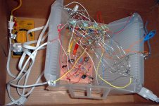
The resistors I had on hand were a potpourri of 1/4W and 1/2W metal film Rs of various physical sizes. It would have been nice to use all 1/2W Dales, but I wired them point-to-point dead bug style (my first attempt), so it was going to look ugly anyway. Most of them were 1% tolerance so they should be fine. Below is a close-up of the PtP wiring. Looks like something you'd find in a dark corner of a garden shed. To my surprise and delight, both channels worked upon first power-up.

...
...
Rayma, 6-32. I've had pretty good luck with 4-40. Reading up on broken taps and the extraction thereof, #6-32 seems to be one that a lot of people break. In my case it was just impatience and not clearing the chips enough.
Yeah, probably not enough oil and patience, if it's a #6 tap.
I won't use #4 taps any more, though.
It would have been nice to use all 1/2W Dales, but I wired them point-to-point dead bug style (my first attempt), so it was going to look ugly anyway.
That's nothing.
Attachments
[Pictures are of details/close-ups only because there's an Easter egg of sorts that I want to keep hidden until the final reveal. That Easter egg depends on a part I ordered from Home Depot, which should arrive in a couple of weeks]
Here's an example of the kind of warped thinking that infects a DIYer's brain...
In my boxes of parts I could only find three fender washers to mount the FETs. So, rather than walk or drive a 1/2 mile to the hardware store down the street to buy a fourth fender washer for 15 cents, I used some scrap 1/8" aluminum and fashioned some FET pressure plate things (or whatever they're called):

...
Here's an example of the kind of warped thinking that infects a DIYer's brain...
In my boxes of parts I could only find three fender washers to mount the FETs. So, rather than walk or drive a 1/2 mile to the hardware store down the street to buy a fourth fender washer for 15 cents, I used some scrap 1/8" aluminum and fashioned some FET pressure plate things (or whatever they're called):
...
I think they're called FET pressure plate things.Here's an example of the kind of warped thinking that infects a DIYer's brain...
In my boxes of parts I could only find three fender washers to mount the FETs. So, rather than walk or drive a 1/2 mile to the hardware store down the street to buy a fourth fender washer for 15 cents, I used some scrap 1/8" aluminum and fashioned some FET pressure plate things (or whatever they're called):
...
")
That's not warped; that's brilliant. Excellent work on those. I can't wait to see the finished product. Last year I purchased an interesting heatsink at a hamfest with the intent of building a stereo version from scratch. This thread might just spur me into action (finally!).
Mr. Z,
My ACA concept II (link in first post) was inspired by a couple of heat sinks I bought at a surplus store. My H2V2 build was inspired by some scrap leather I had laying around. Go for it!
My ACA concept II (link in first post) was inspired by a couple of heat sinks I bought at a surplus store. My H2V2 build was inspired by some scrap leather I had laying around. Go for it!
Well, a couple of weeks turned into a month, but the ACA is finally finished, save for a few cosmetic tweaks. Here's a pic of the completed amp:

Maybe hard to tell from the pic but the front and top are mirrored acrylic. The most challenging part of the build was the power switch. I swear I've got a compulsion to make things more difficult than they have to be. Here's the switch assembly:

Turning the knob 90 deg. Turns on the amp and the knob glows red (looks better in low light):

Turn the knob another 90 deg. illuminates the Interior, revealing the PASS logo, made from double sided pcb material and serving as a ground plane for the circuit:

Here's a picture of the guts:

And here's a picture of the amp in its milieu, playing "Lawyers, Guns, and Money" by Warren Zevon:

Overall, I'm very pleased with the results!
Cheers!
Maybe hard to tell from the pic but the front and top are mirrored acrylic. The most challenging part of the build was the power switch. I swear I've got a compulsion to make things more difficult than they have to be. Here's the switch assembly:
Turning the knob 90 deg. Turns on the amp and the knob glows red (looks better in low light):
Turn the knob another 90 deg. illuminates the Interior, revealing the PASS logo, made from double sided pcb material and serving as a ground plane for the circuit:
Here's a picture of the guts:
And here's a picture of the amp in its milieu, playing "Lawyers, Guns, and Money" by Warren Zevon:
Overall, I'm very pleased with the results!
Cheers!
- Home
- Amplifiers
- Pass Labs
- ACA Concept III: ACA with (mostly) parts I had laying around