The schematic is Andy's. There is not enough detail to see what can be wrong.
If it worked with the diodes, it should work OK.
Does the input voltage really measure 14,5V?
If it worked with the diodes, it should work OK.
Does the input voltage really measure 14,5V?
Forgive me, but this is the same question that we had when you changed to the SiC diodes. And I suspect that the problem is the same (the voltage was measured in the wrong place).
It was only possible to find the problem when you drew the circuit, in pencil, and labelled exactly where each voltage was measured.
There was no problem with the circuit, but you measured the voltage in the wrong place
Using Andy's schematic is no good.
It has to be carefully drawn exactly as you built it. The exact points where the DMM was connectd must be labelled.
Can you find the circuit you drew last time? it should be just what you need
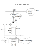
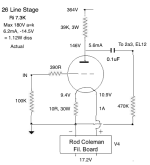
The schematic in post #1 is not my values. See below. Obviously, if you have 7V on the cathode with a 1 amp filament then the cathode resistor is 7 ohms not 10 ohms. That's using Rod's old regs before V9.

IF the R.C. regulator current is EXACTLY 1A, on EXACTLY 10R bias resistor these are the expected voltage values (below the red circle).

Other values (except of anode current) of this (my old #26 preamp) schematic are indifferent.
On the 10R resistor the current is sum of R.C. regulator current and anode current.
Other values (except of anode current) of this (my old #26 preamp) schematic are indifferent.
On the 10R resistor the current is sum of R.C. regulator current and anode current.

Several questions:
-How important is the grid stopper, 26 it's prone to oscillate by self?
-To measure the filaments I guess that B+ is to be connected?
-What's the pin number of filament positive & negative or no matter as I guess because tube can go AC or DC?
-How important is the grid stopper, 26 it's prone to oscillate by self?
-To measure the filaments I guess that B+ is to be connected?
-What's the pin number of filament positive & negative or no matter as I guess because tube can go AC or DC?
Last edited:
You don't have to connect B+ to set up and measure the filament bias and regs. The resistor is sized by the filament current and the tiny current of the 26 will make no difference.
Rod answered the grid stopper question a number of posts ago - it can be left out on certain conditions of very close proximity of all elements. I put in 220 to 390 ohms just to be sure.
Rod answered the grid stopper question a number of posts ago - it can be left out on certain conditions of very close proximity of all elements. I put in 220 to 390 ohms just to be sure.
It's OK both ways.-What's the pin number of filament positive & negative or no matter as I guess because tube can go AC or DC?
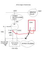
As requested attached pics.
Attachments
-
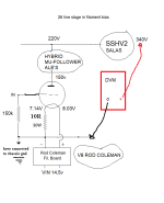 B+ before SSHV2 26 FILAMENT BIAS RESISTOR 10R.png13.9 KB · Views: 99
 -
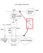 B+ before Hybrid Mu-Follower 26 FILAMENT BIAS RESISTOR 10R.png14.2 KB · Views: 90
 -
 B+ Anode 26 FILAMENT BIAS RESISTOR 10R.png13.8 KB · Views: 97
 -
 Positive Ror Coleman FILAMENT BIAS RESISTOR 10R.png13.7 KB · Views: 97
 -
 Negative Rod Coleman FILAMENT BIAS RESISTOR 10R.png14 KB · Views: 101
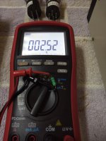
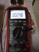
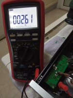
What type of resistor is it?
What does the meter read when the red and black leads are connected together?
What does the meter read when the red and black leads are connected together?
You still have 10 ohms for the cathode resistor. This will not work. You need to change it to 7 ohms or 6.8 ohms to get 1 amp going through the filaments with 7V bias. This is simple Ohms Law. It's not advisable to starve the filaments of a 26 either.
If you want to use 10 ohms as cathode resistor with Rod's older regs you need values like this attached.
If you want to use 10 ohms as cathode resistor with Rod's older regs you need values like this attached.
Attachments
I use calibration function so 0 ohms....What type of resistor is it?
What does the meter read when the red and black leads are connected together?
Are the included in your kit.What type of resistor is it?
What does the meter read when the red and black leads are connected together?
What does the working channel's R1 measure?Attached pic of measured R1 & R2, way off the 1R value.
Felipe,
Before use any "new" device, must be set the working parameters.
Without any tube, feed the filament bias resistor (example 10R) series connected 1R5 (as tube filament 1.5V/1A -put it to socket filament pins-) with R.C. regulator.
Set the R.C. regulator to 1A.
Measure voltage headroom on R.C. regulator (between "input" and "output"). If it corresponds to Rod recommended value, the regulator working properly.
If the regulator stabilized (steady 1A), turn off and put tube to the socket.
Measure filament voltage on socket pins.
- Home
- Amplifiers
- Tubes / Valves
- 26 preamp Rod Coleman V8 problem