Crossover design. How hard is to add a Woofer to a 2-way and make it 3-way?

Hi everyone.

So let’s say I have a small bookshelf speaker and want to extend with a bass woofer resulting in a 3 way.
Is it a complete x-over design case ?

Theoretical cross point between midrange and woofer let’s say 400hz as a starting point
Speakers will be 15W 8530 K00 in sealed Enclosure reaching 80hz -f3 as a woofer and Sica 5.5 C 1.5 CP in another sealed compartmend.
Estimated x-over point 400-600hz (what is best )
Speakers will be crossed to Subwoofer at 80-90 hz and will never play without Subwoofer.
Spl should not be an issue , i am sitting max 1 meter from speakers.
I am planning on going fully active in the future but for now i need to make the Speakers (15w+Sica coax) work together passively)

MosFET getting hot in amp - with no load

Hello guys,

I've got an amplifier with 2 Fets IRFU4615 driven by IRS20124S.
Problems:
1) Fets get hot after less than 1 minute, with no load.
2) I have 0.7V more on the +OUT than on the -OUT (the -OUT being connected directly to the middle of 2 supply voltage capacitors = 130VDC, while the +OUT is coming from the Fets). For example: If I have 63V on the -OUT, then, I will get 63.7V on the +OUT which comes from the Fets through a coil.

The amplifier seems to work fine, sound is OK, before the Fets get hot.
What should be tested? What could be wrong?
I will attach a simple scheme, and scope diagrams of some pins.

What should the signal look like on the gates of the Fets, if no load/audio signal present?

Thanks you all....

Soundbar full digital amp

Hi,

So I am going to build myself a small soundbar for my monitor using two Markaudio Alpair 5.3 FR drivers (85dB sensitivity, 5W nominal, 3.4 Ohm according to spec sheet).

No issues with the box etc; where I am completely lost though is on the digital transport/DAC/amplification side of things.

As source I can offer up either USB passed from PC via monitor to soundbar, or 3.5mm jack out the back of monitor to soundbar.

Are there any simple all-in-one options out there that would accept audio over USB in, and drive these two cones? I'm not fussed re Bluetooth, and at this stage in the journey leaning towards mid-range quality vs. price (i.e. not no-holds-barred quality, and not bottom-of-the-barrel price).

Modifying Denon DCD-S1 IV stage,opinions needed

I have reverse engineered DCD-S-1 IV output stage (4x pcm1702) as no schematics were possible to acquire. it have really nice passive parts but seems some strange desisions like diferent ground resistors for balanced out(6.7K and 20K- triple checked that), and high output resistors(4.23K, 6.7K)

IC5 GIC filter (?) seems also best ommited.

If understand corectly schematics IC 1,2 is I to V converters, IC4, summing amp, IC 3 bufer, IC6 SE to diferential with gain less than 1?

I would like to have dedicated balanced out(5-6V RMS) instead of suming and balancing again (RCA- 3V rms)

my preliminary modified schematics is here, I have reduced most resistors to 2K as I have plenty of them (Vishay metal bulk foils) I ahve also included direct out for xlr as sugested. Enclosure is big I can make extra few holes foraditional XLR. (I supose direct XLR out wont be sucifient for 10K input impedance ampas with gain less than 28db)

opinions and corections needed. thanks in advance.

Attachments

  • DSC_1845.jpg
    DSC_1845.jpg
    276.4 KB · Views: 247
  • DSC_1859.jpg
    DSC_1859.jpg
    287.5 KB · Views: 202

Anthem MRX720 with Blown IT7673M Regulator

Good day. The Anthem MRX720 has a charred IT7673 (step-down DC/DC converter, already removed in the picture but not cleaned yet). After removing it there's no more ground short.
The chip provided power to the DSP section so I continued probing around the section and found no more faults, to the best of my ability.

The chip has been discontinued. Through email correspondence with manufacturer they said there is no substitute.
I can only find them on Aliexpress or Ebay from China. I had some bad experience getting counterfeit semis from China, but the manufacturer is iTE from China so I figured there's still chance.
I've placed an order and it will take a while to arrive.

Here's my question,
The boards has several same chips to power individual HDMI sections.
How safe is it to use one of those for testing while waiting for the chip to arrive? When this chip fried the amp powered up fine but no sound.
I figure the HDMI section is more complex and removing one chip would be more complicated than just losing a power rail unlike the DSP section.

They emailed me the PDF datasheet for the chip but it has been plastered with large 'CONFIDENTIAL' words on it so I don't think I can attach it here.

Attachments

  • WhatsApp Image 2024-01-19 at 4.50.32 PM (1).jpeg
    WhatsApp Image 2024-01-19 at 4.50.32 PM (1).jpeg
    236.6 KB · Views: 192
  • WhatsApp Image 2024-01-19 at 4.50.32 PM.jpeg
    WhatsApp Image 2024-01-19 at 4.50.32 PM.jpeg
    237.5 KB · Views: 202

Spring Reverb Circuit Problems

I have a cheap little reverb tank that I'm trying to turn into a 'guitar pedal' but now it is having some probs. Earlier on the breadboard, the tank did work.

On the coils, I'm currently measuring 46ohms (DC) across the tank's input and 156 ohms on the output, so they are not 'open'.

I have a TL072 sending signal just fine to the input coil. And the other half of the IC is picking up the output just fine (if you shake the springs by hand, using my audio probe).

But, I am not getting any of my input signal coming through the springs.

Visual inspection and continuity checks all seem to be ok.

I tried direct-injecting a 'headphone' output from a cassette deck straight into the tank, same story.

This is the schematic (Blues Junior) I've been basing it on:

https://www.tubesandmore.com/sites/...er/img/spring_reverbs_fender_blues_junior.svg

And the page it comes from:

https://www.tubesandmore.com/tech-articles/spring-reverb-tanks-explained-and-compared


Any suggestions for how to further trouble-shoot would be greatly appreciated!

Neurochrome Modulus-186: 40W (8Ω); 65W (4Ω) @ <-120dB THD Composite Amplifier Module

Neurochrome Modulus-186: 40W (8Ω); 65W (4Ω) @ <-120dB THD Composite Amplifier Module

Update 2018/10/20: The introductory sale has started: Modulus-186: 65W composite amplifier achieving <-120dB THD
The sale will end by 23.59 Mountain Time (GMT-7) on November 30th. This will be the only sale on the Modulus-186 so get 'em while you can.

Key features (preliminary):
  • Mono construction.
  • 40/65 W into 8/4 Ω, respectively @ THD < -120 dBc.
  • Tested for stability with reactive loads up to 1.0 µF || 8 Ω.
  • Multi-tone IMD residual: < -105 dBV.
  • Damping factor: >500 @ 1 kHz; >225 @ 20 kHz (8 Ω).
  • Integrated noise (20 Hz - 20 kHz): 17 µV (A-weighted); 22 µV (unweighted) @ 20 dB gain.
  • Integrated noise (20 Hz - 20 kHz): 23 µV (A-weighted); 28 µV (unweighted) @ 26 dB gain.
  • Balanced input (can be connected to unbalanced sources as well).
  • Default gain: 26 dB for ease of use with other HiFi components. 20 dB available upon request. Higher gain possible by a simple resistor swap.
  • Four-layer PCB, fully optimized for the highest performance.
  • Designed, manufactured, and assembled in Canada. All components sourced from reputable distributors (Mouser, Digikey, et al.)
  • Available for pre-order within the next few days with a significant early adopter discount. Expected in stock by the end of November, 2018, at which point the into sale will end.
The Modulus-186 is a composite amplifier, which uses an LME49720 to perform error correction on an LM3886 power amplifier. This results in an amplifier which has the precision of the LME49720 and the power of the LM3886. This error correction is the central point of the Neurochrome Modulus composite architecture. The composite design will correct for many types of error, including distortion and power supply induced errors. It is due to this architecture that the Modulus amplifiers achieve their high performance levels as evidenced by their ultra-low THD, IMD, multi-tone IMD, etc.

Note that attached picture and measurements are of the prototype. I will follow up with a more comprehensive set of measurements once the production version is in.
The production version will be Neurochrome Blue and professionally assembled in Calgary on a gold-plated PCB made in Ontario, Canada. The finished module will include aluminum mounting hardware (also made in Canada), which allows the module to be bolted directly onto a heat sink. This mounting method greatly simplifies the mechanical work for the the DIYer (only two holes needed with ±0.5 mm precision in their location).

Enjoy.

Tom

Attachments

  • MOD186_PROTO.jpg
    MOD186_PROTO.jpg
    338.6 KB · Views: 1,533
  • Modulus-186 PROTO_ THD+N vs Output Power (20 dB, 1 kHz, 8 ohm, 20 kHz BW).PNG
    Modulus-186 PROTO_ THD+N vs Output Power (20 dB, 1 kHz, 8 ohm, 20 kHz BW).PNG
    41 KB · Views: 1,511
  • Modulus-186 PROTO_ THD+N vs Frequency (20 dB, 40 W, 8 ohm, 60 kHz BW).PNG
    Modulus-186 PROTO_ THD+N vs Frequency (20 dB, 40 W, 8 ohm, 60 kHz BW).PNG
    34.9 KB · Views: 1,444
  • Modulus-186 PROTO_ THD+N vs Output Power (26 dB, 1 kHz, 8 ohm, 20 kHz BW).PNG
    Modulus-186 PROTO_ THD+N vs Output Power (26 dB, 1 kHz, 8 ohm, 20 kHz BW).PNG
    40.6 KB · Views: 1,415
  • Modulus-186 PROTO_ THD+N vs Frequency (26 dB, 40 W, 8 ohm, 60 kHz BW).PNG
    Modulus-186 PROTO_ THD+N vs Frequency (26 dB, 40 W, 8 ohm, 60 kHz BW).PNG
    35.4 KB · Views: 1,405
  • Modulus-186 PROTO_ Multi-Tone IMD (AP 32-tone, 40 W, 1M FFT, 8 averages).PNG
    Modulus-186 PROTO_ Multi-Tone IMD (AP 32-tone, 40 W, 1M FFT, 8 averages).PNG
    64.8 KB · Views: 317
  • Modulus-186 PROTO_ Residual Hum & Noise (1M FFT, 8 averages).png
    Modulus-186 PROTO_ Residual Hum & Noise (1M FFT, 8 averages).png
    48.3 KB · Views: 416

another what is it?

I was asked by a friend what this could be?

1708617243160.png


He is a hobbyist train fanatic - this is a part on a 1950's engine (model train) and has voltage wires coming in and then leading out to other parts.

My guess was a splitter of sorts but if anyone here has any pearls to offer, he would be very grateful for any guidance.

thx..dB

LuFo Amp - 39w SE Class A from 28v Rail

Update Nov. 2, 2021 - Final manufacturing files with Vds bias voltage mod for LU1014D as suggested by Mbrennwa. Files are located here. A huge thank you to JPS64 for making the mods to the layout.

Update Oct 19, 2021 - Final manufacturing files (Gerbers, BOM, schematics) can be found here. A big thank you to JPS64 for making the beautiful layout.

In the course of testing the new aluminum IMS PCB adapter board for the LU1014D group buy by member Wg45 (with LU1014D's provided by Mr Pass, and the testing is being performed by Woofertester), I realized that the LU1014D can carry a lot of current and can now be cooled easily and effectively. The ability to mount and cool it easily, combined with the use of a MOSFET cascode stage to increase the rather low 20v limit gave this little transistor new life as an audio output stage. Inspired by Michael Rothacher's (and his alter ego, the “Dude”)excellent 
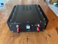
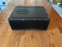
MoFo amp, which I built several years ago when it first came out, I saw that something simple and similar could be done here. I wanted to make something that folks could easily make using scraps from their bench without resorting to a high dissipation MOSFET like an IXYS, or fancy CPU coolers and fans. No, just conventional IRFP240's can be used and at safe levels of dissipation of only 25w each - suitable for mounting on a passive radiatior heatsink like a 4U x 300mm one from Modushop.

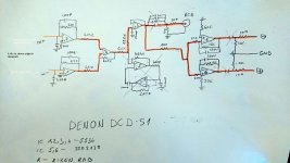
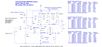
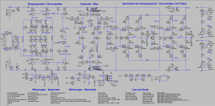
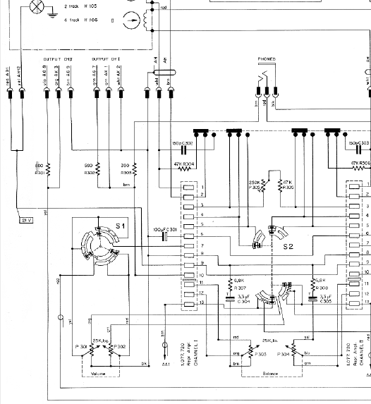
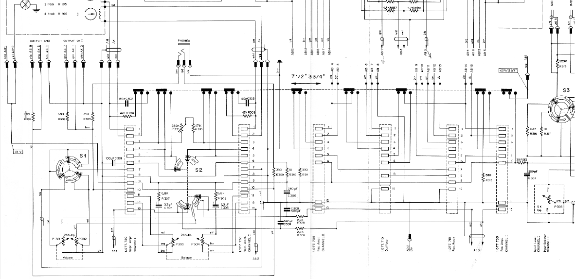
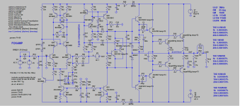
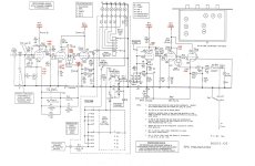
Here is the resulting schematic from LTSpice doodling. It has a minimal parts count, yet the performance is quite nice. With a 28v supply and about 3 amps of bias current, the simulations predict that it can get up to 39w into 8ohms before clip sets in. The THD at full power is a little over 0.13% but only 0.01% at 1w into 8ohms and 0.03% at 8w into 8ohms. Of course, all this is with a nice SE Class A harmonic profile that is dominant second order and monotonically descending higher orders.

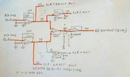
Here is the schematic:
954037d1621739943-lufo-amp-39w-se-class-28v-rail-lufo-triple-irfp240-v1-png


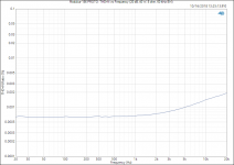
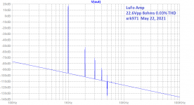
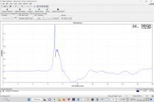
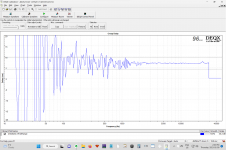
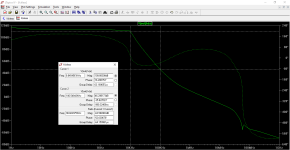
Here is the predicted FFT for 1w into 8ohms (8vpp) - it gets 0.01%THD and a beautiful harmonic profile:
954038d1621739941-lufo-amp-39w-se-class-28v-rail-lufo-predicted-fft-8vpp-8ohms-png


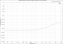
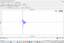
At an average and rather loud level of 8w into 8ohms - it gets about 0.03% THD and still maintains a nice harmonic profile:
954039d1621739943-lufo-amp-39w-se-class-28v-rail-lufo-predicted-fft-22-6vpp-8ohms-png


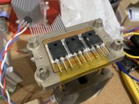
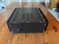
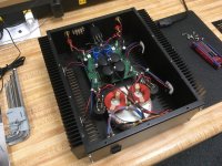
For the purposes of a proof of concept build, I am using CPU coolers and a Noctua fan since I have a pile of them and only 1 conventional 4U x 300mm chassis from Modushop, currently occupied by an Alpha Nirvana (which, btw, has the same output power and dual rails). But the PCB that JPS64 will be doing the layout for me will be a large conventional design with widely spaced MOSFETs (probably UMS compatible). Here is how I am stacking the three MOSFETs (some NOS Phillips PSMN020 150w's that Hugh Dean gave me a while ago) on the Dell CPU cooler, to which I will directly solder a veroboard and build the amp on:
954040d1621739943-lufo-amp-39w-se-class-28v-rail-lufo-build-01-jpg


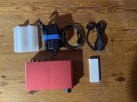
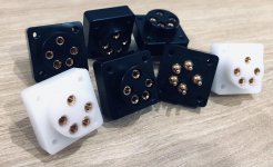
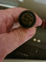
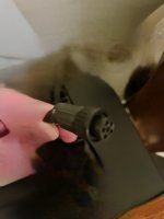
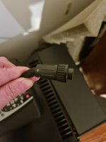
Here is how the LU1014D is mounted onto an IMS PCB adapter that lets it be used like a TO-247:
953093d1621440649-lovoltech-lu1014-power-jfet-buy-lu1014d-to247-adapter-heatsink-02-jpg


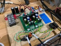
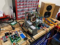
Here is a closeup of the completed amp - all of it fits on the little veroboard - except the LU1014D and the 67mH (0.5ohm DCR) microwave oven transformer (you can get surplus (MD 803AMR model) ones similar to this one on eBay), which are attached with 18ga silicone wire flying leads and pin end crimped tips for the screw terminal blocks:
954041d1621739943-lufo-amp-39w-se-class-28v-rail-lufo-build-02-jpg


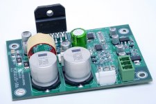
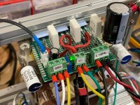
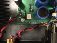
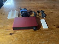
I am using an active bridge (LT4320) rectifier, with a CRC, and a BJT cap multiplier single rail PSU (I measured ripple under 3A load at less than 1mv rms). Although, I think this amp has decent PSRR due to the cascode feedback - so a conventional CRC might just work swell without audible hum:
954043d1621739943-lufo-amp-39w-se-class-28v-rail-lufo-build-05-jpg


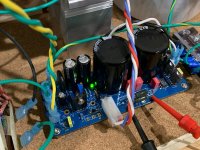
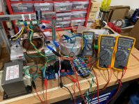
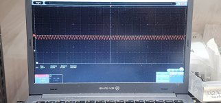
Here is the first power on test, the amp reached 3A bias current, the voltage at the LU1014D source pin was around 1.5v, and the voltage at the LU1014D drain pin was around 4.2v - pretty much spot on from the simulations. No magic smoke was emitted, and everything was stable. I adjusted the trimpot slightly to achieve about a 3v difference between the drain and source pin of the LU1014D:
954044d1621739943-lufo-amp-39w-se-class-28v-rail-lufo-build-06-jpg


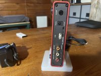
I then connected the Pass ACP+ as the preamp - knowing that this will not achieve the full power since it does not have the ability to put out 50Vpp swing - but it will let me test the sound a reasonable volume:
954042d1621739943-lufo-amp-39w-se-class-28v-rail-lufo-build-04-jpg


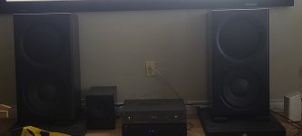
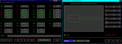
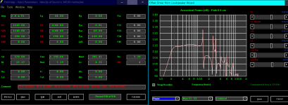
Here it is playing music - it sounds great! I also tried it with a Melbourne preamp that can swing 55Vpp and it does indeed play loud. The bass impact is particularly good for a SE Class A amp. The combination of the low Rdson of the LU1014D and the reactive load of the 67mH microwave oven transformer (MOT) combine to give this amp a predicted damping factor of 157 at 50Hz:
954045d1621739943-lufo-amp-39w-se-class-28v-rail-lufo-build-07-jpg


This amp sounds very nice - smooth and similar to the MoFo, but with a different - more muscular feel, perhaps a bit less distortion. It certainly is easy to build and if you already have a MoFo, you are 80% there. It works fine at 20v or 24v too - just lower output power.

It is a simple and easy amp to build - you will need either a Hammond 193V inductor or pull one from an old microwave oven (or buy those on eBay for about $25) and a powerful preamp if you want to reach the full 39w potential.

We now wait for JPS64 to design us one of his masterpiece PCBs - this should be really cool.

Edit May 26, 2021: max power before onset of clipping is 17.77vrms into 8ohms. That’s 39.5w.
955036d1622062551-lufo-amp-39w-se-class-28v-rail-df15f3c7-978b-4edd-b7e8-d3d1367aba0d-jpeg


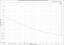
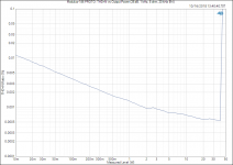
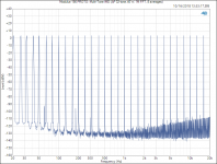
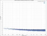
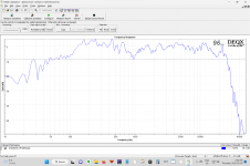
Edit May 24, 2021: Measurements for 1kHz 2.83vrms into 10ohms
954528d1621898005-lufo-amp-39w-se-class-28v-rail-lufo-2-83vrms-10ohms-fft-jpg


8Vrms into 10ohms:
954530d1621898005-lufo-amp-39w-se-class-28v-rail-lufo-8-0vrms-10ohms-fft-jpg


Mouser shopping cart here (thanks to Vunce):
LuFo Amp - 39w SE Class A from 28v Rail

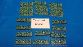
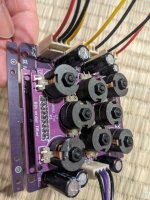
Prototype LuFo UMS compatible production board built by Vunce:
961586d1624332091-bench-tonight-obt-7a850f46-9d48-493b-8521-32a5d2da0194-jpeg


June 25, 2021 - Vunce’s verification build in stereo:
962669d1624677595-lufo-amp-39w-se-class-28v-rail-13edfc1a-733e-41ba-bb0c-875b701dbc37-jpeg


June 28, 2021 - Note that use of non-audio specific chokes like MOTs or Hammond power supply filter chokes may not provide optimal performance when playing sustained bass heavy tracks - this will deplete the magnetic energy stored in the choke and may cause intermittent clipping of high crescendos when preceded by deep bass lines. More info here:
LuFo Amp - 39w SE Class A from 28v Rail

Edit July 10, 2021: LuFo Lite - a 5.6W 12vdc supply LuFo without a cascode:
966134d1625949084-lufo-amp-39w-se-class-28v-rail-lufo-lite-schematic-v1-jpg

Attachments

  • LuFo-Triple-IRFP240-v1.png
    LuFo-Triple-IRFP240-v1.png
    118.7 KB · Views: 15,917
  • LuFo-Predicted-FFT-8Vpp-8ohms.png
    LuFo-Predicted-FFT-8Vpp-8ohms.png
    33 KB · Views: 13,753
  • LuFo-Predicted-FFT-22.6Vpp-8ohms.png
    LuFo-Predicted-FFT-22.6Vpp-8ohms.png
    27.7 KB · Views: 11,365
  • LuFo-Build-01.jpg
    LuFo-Build-01.jpg
    287.5 KB · Views: 10,952
  • LuFo-Build-02.jpg
    LuFo-Build-02.jpg
    366.4 KB · Views: 15,350
  • LuFo-Build-04.jpg
    LuFo-Build-04.jpg
    436.6 KB · Views: 10,347
  • LuFo-Build-05.jpg
    LuFo-Build-05.jpg
    408.7 KB · Views: 11,416
  • LuFo-Build-06.jpg
    LuFo-Build-06.jpg
    506.5 KB · Views: 14,804
  • LuFo-Build-07.jpg
    LuFo-Build-07.jpg
    503.5 KB · Views: 10,314

Constant current for heaters?

Good morning, afternoon and evening.

I'm new to tubes/valves so I'm starting with a simple preamp and seeing how it goes.

The circuit uses two miniature double triodes with their heaters in series. I'm running this from a 300mA constant current from an LM317. With only 47uF between bridge and regulator I'm getting almost no hum (sorry to be so subjective, but it's inaudible below the white noise - at some point I'll low pass and attempt to measure).

Is there any reason I shouldn't persist with this? Seems sensible to me as the valves take a long time to warm up, there's no surge on the bridge from cold heaters and empty 4700uF capacitors, and as the output is a cathode follower the DC output voltage rises slowly, eliminating turn-on thumps. But I've never heard of anyone using CC to drive heaters.

thanks
  • Like
Reactions: jan.didden

Repurpose vertical output autoformer?

I happen to have a NOS Triad A-104X vertical deflection output autofomer. It is fairly large in size and has three leads, marked ratio 18:1, with a measured resistance of about 1.5k between the blue and red leads, about 5 ohms between red and green.

I have no use for it as its intended purpose, but I wondered if it might serve as a choke in a tube power supply. Or if it had any other audio use other than its original purpose.

Revisting the Gedlee Abbey

Working on some of my own speaker designs has made me appreciate the Abbey's more. I finally took them outside on my back patio
to do some correction with my DEQX so I thought I'd post the anechoic responses I took outside for the group. I find at least with the deqx
they (and most) speakers sound better when I dont touch the eq (even if its wavy gravy) and just correct the group delay and step response and phase.

This gives me the most realistic soundstage. I think its something about the various filters that doesnt do as well correcting magnitude for some reason.
I upgraded these from the DE250 to the DE500 Neo compression drivers. The woofers are the non neo BC B&C 12TBX100 I would like
to hear from anyone who has also upgraded the woofers to the neo version if it made a significant difference. Whoever built these (I had them
imported all the way from Poland!) Used premium caps and resistors. I wont post pictures of the crossover to protect Earl's IP.

They also do really well tilted up against the wall on the floor under a projection screen like I have. the 132hz f3 gets filled in nicely down to around
80hz by room gain to mate with a sub.

Attachments

  • 2.png
    2.png
    79.2 KB · Views: 343
  • 3.png
    3.png
    77.3 KB · Views: 259
  • 4.png
    4.png
    95.7 KB · Views: 250
  • 5.png
    5.png
    95.6 KB · Views: 253
  • image.png
    image.png
    86.2 KB · Views: 324
  • 6.jpg
    6.jpg
    156.4 KB · Views: 346

Twisted Sounds 3.5k

This amp powers up and functions but the output fets heat unevenly between sides. One side stays cool while the other will get up to 120f at idle.

I removed the fet fets from the side that was heating up and I'm seeing a weird triangle wave on the output fet pads that should have nothing on them.

Attachments

  • 17072419794333245680061981622721.jpg
    17072419794333245680061981622721.jpg
    315.5 KB · Views: 72

Hello from Munich, Germany

Hello everyone

My name is Matthias and I'm from Munich, which some of you might know from our rather large beer festival. ;-)

I have always been interested in audio gear, listening a lot since my youth, but only recently I discovered DIY by building the "Le Petite" speakers by Jean Hiraga ( https://snakeoilaudio.de/diy.html not my site, just for reference).

As the speaker is currently driven by an old Pioneer A616 amp, it's time to upgrade it. So I plan to build the new First Watt F5M together with the B1 Korg Nutube. Fingers crossed that I'll be able to get all the necessary kits in the shop at once when they're out. 🙂

Looking forward to a new journey into DIY and thanks a lot in advance - especially to Nelson Pass - for all the great inspirations and the newbie friendly way here at diyAudio!

Bye bye

Matthias

For Sale Pass Zen Revisited Prototype, Reluctantly for Sale

I really do not want to sell this as it is such a cool piece of history, but it really is time to thin the heard. It has been on display as an art piece in my home library.

More info on it here:

https://www.diyaudio.com/community/threads/help-with-provenance-pass-labs-zen.365813/

Please note, the amp in that thread for $150 is not this amp, it was one that sold on Audiogon a few years ago. I purchased this at Fidelis Audio in Nashua NH for $400, and I am asking for $400 plus shipping - not looking to gouge someone on it. Hoping this can go to a good home where it will be appreciated.

Please feel free to ask questions.

Attachments

  • IMG_0096.jpg
    IMG_0096.jpg
    521.9 KB · Views: 237
  • IMG_1524.JPG
    IMG_1524.JPG
    828.1 KB · Views: 239
  • IMG_1522.JPG
    IMG_1522.JPG
    658.9 KB · Views: 242
  • IMG_0098.jpg
    IMG_0098.jpg
    582.4 KB · Views: 216
  • IMG_0097.jpg
    IMG_0097.jpg
    613.3 KB · Views: 211

For Sale NuForce Icon IDO iOS DAC for iPhone, iPad

This DAC is specifically made for iOS devices with a USB-A input, analog and digital outputs.

The digital out is interesting as you can connect it to a device with digital inputs and capture the digital signal.

In very nice shape, works perfectly.

Included an Apple Remote for volume, play/pause and track FWD/Back.

Cables included. Not sure if it works with newest USB-C iOS devices, but I suspect so with the correct cable.

Asking $50 plus shipping.

Attachments

  • IMG_0056.jpg
    IMG_0056.jpg
    452.2 KB · Views: 69
  • IMG_0055.jpg
    IMG_0055.jpg
    562.4 KB · Views: 62
  • IMG_0053.jpg
    IMG_0053.jpg
    541.3 KB · Views: 57

REL R-258 blown PSU component identification

REL R528 sub PSU component identification

Hi guys, I have taken a rel r528 amplifier board in for a repair and a couple of the large capacitors have failed, whilst doing so it appears to have blown a component on the underside of the PCB. The damage prevents me from being able to get the part number for it as it's obliterated. I have searched for a service manual with no joy so I would appreciate it if anyone can help me identify the component I need. The silk screen markings are R6 as far as I can make out as the area is blackened around it a bit. The damaged track is to the middle pin of a 13003 transistor on the top side of the board and the other connecting track goes off to an mpsa44 transistor. I have attached some photos for assistanceIMG_20230826_212758.jpgIMG_20230826_212920.jpgIMG_20230826_212957.jpgIMG_20230826_213021.jpg

RIAA preamp tweaking?

This is a phono preamp module out of a Sansui amp.
A few questions regarding its possible enhancement...

First off, in testing, it sounds fantastic, with a claimed +/- 0.5dB accuracy to the RIAA specs.
That spec, I don't really want to mess around with.
However, what I want to possibly do is to be able to give it a small +3dB "boost" of it's output.
I don't want to change the IC either, it sounds fine.
I also want to (if possible) lower it's already fine output noise a tad.
Residual hiss can only be heard with no signal if ear is near speaker, but not big worry.

Would changing the value of the 100 ohm feedback resistor R6 or R7 be a way to give the output a boost? - and if so, would it make a difference in the RIAA spec?
OR... would the addition of a simple NPN transistor at the output be more suitable?

Thoughts?

F-3333 preamp.jpg

Crossover design to "fix" already existing box/drivers.

My dad replaced some worn out drivers in some old thrift store boxes with some inexpensive stuff from parts express. He just dropped them into the box on the old crossover and away he went.

Not a fan of the sound, I wouldnt have called it warm, neutral, or bright, weirdly enough, and i know how picky crossovers can be. Made some files from the charts for the grs/dayton drivers he chose, and simulated it with the crossover thats in there, thats PIC#1. The Crossover like an off the shelf job someone used to replace a single woofer inductor/tweeter cap(hanging loose in box still lol). the 400-700hz peak is very audible and it's what had me messing with xsim. I left the individual driver curves out because its an absolute mess, i couldnt even tell you what the crossover points are looking at it. It was bad, very very bad.

The second series resistor on the mid range is a variable potentiometer he wants to keep, and honestly it helps me out anyway.


I have a decent understanding of what im doing, but pretty novice with crossovers in practical application. Pic #2 is the flattest freq response, phase, and impedance i can muster after many hours of tweaking values. (im kinda shocked i got it that flat, there's a $7 sealed back GRS midrange, and $19 grs woofer in there, def the two hardest to make work drivers ive played togetherwith in xsim, Crossover points about 680hz/2.2khz, from like 1400hz and, idek, 10khz? They basically ran together from 10khz all the way to 16khz 🤷‍♂️


Being a novice that hans't ever built a crossover from scratch, just lightly modified existing ones, and tinkered with Xsim time to time in curiosity, Is there any obvious reason im overlooking that i shouldn't build this crossover, or something else i need to change in it before its worth building? These were thrift store speakers, far from his main system, and my dad has no attachment, so i have free range to tinker and learn. Stock xover is all electrolytic caps too, id be using (mostly) film.

Pic#1 Current xover
Current crossover.PNG

#2
NewXoverDesign.PNG

The "JCN-JX1" Mosfet amplifier

Hello,

here I want to introduce my actual project.
To the background: My previous project was a Pass Aleph-JX amplifier which works very file. The next step should be a .5/.8 clone, but for severals reasons I decided to build up an independent project, but with some "Pass-DNA" - the full balanced circuit, low count of amplification stages, and a current source at the outputs to rail voltage.

So after a lot of LTSPice twiddling I came to the following circuit.
The basis is a symmetrical JFET input stage in the "John Curl style", built as folded cascode to avoid a 2nd voltage stage.
Its followed by a Mosfet output stage - since the folded cascode is high impedance the Mosfet output stage (or perhaps a triple) is mandatory for low distortion figures. In order to drive the Mosfets with high speed I also introduced a simple driver stage.

Thats in principle an easy circuit, but in detail it became a bit more complicated to solve all details. Common mode offset and so on.
At the end I think it works very well and during prototyping I never has issues with oscillation although I would call it a quite "fast" circuit, capable of slew rates above 200V/us. With the shown (quite simple) bias spreader and IRFP140/9140 the bias is rock stable. Thermal compensation can be altered easily by chosing annother zener / resistor combination.

Because there is only one voltage amplification stage, the open-loop-gain is somewhat limited to a maximum around 60dB. Therefore the amp is designed for high Class-A bias. But for "casual listening" an optional AB-bias gave also quite good results so it can be used optional.
For this, there a 2 bias pots to set-up different bias values. I have the AB-setting for casual listening (150mA per Fet), watching TV, playing PS etc... and the A (400mA per Fet) for serious listening. At +/-20V Rails this is ~65Watts per channel plus drivers.

Amplifier power is limited by the voltage capability of the input Jfets, the J74 is rated to only 26V. I don't liked do add an "cascode cascode" so the power is limited to ~70V/8R. But it can be increased by adding a zener into the drains of the J74s, found no problem with this so far.

Because of the type of feedback circuit there is a trade-off between gain / input impedance / noise. Without an input buffer by soulution was a 68k/6k8 feedback network which gives 20dB gain and about 9-10k input impedance. With an input buffer the resistors can be lowered, noise decreased and input impedance increased. It depends on personal preference, on my latest board I have the input Jumpered for with / without buffer.

Power supply is a bit special: There is a standard PS for the output stage and boosted rails for input / drivers. In the first stages of development the amp had not the best PSRR, so I introduced a boosted rails filterd by a capacitance multiplier. For simpler built-up I designed a "booster" supply which give doubled rail voltages by adding a Elko and a Diode in the rectifier. So only 1 transformer is neccessary. But of course a normal supply with higher voltage can also be used.

At both outputs (+out and -out, full balanced) I have some CCSs which can be switched of +Ub or -Ub, so there is the possibility to alter the sound a bit by switching the outputs to + or - Ub. But with I=0.4A in the prototype the changed are clearly measureable, but hardly noticeable in the listening test.
In short, both to the same Voltage keeps the H3 characteristic but alters the values, and One to +Ub and one to -Ub gives a H2/H3 characteristic.

I have finished eagle layouts which I would call "fool-proof", but I dont see it as a beginners project.

The big drawback is that it uses the unobtainium K170/J74 combination and there is no way in using other types because their high transconductance is really needed here - and I have 2 in parallel. But only 1 ( => 2 pairs per channel) might also be possible if the drivers used have high beta.
Input stage with BJT is possible, but with a completely redesigned input stage because they need to biased in a different way.

There are severals options: Prototype has 2 Fets in parallel, annother version is with 4 of them with increased rails for >100W/8R and better performance at low impedance loads.
Actually I test at an input stage with full-symmetric reference current source, without servos (I think they are not really neccessary) and a K170/J74 buffer stage in front for lower impedance feedback network = lower noise.

Now some pics and measurement data... and ideas for further improvements are welcome ;-)

Regards, Jean-Claude

Attachments

  • JCN-JX1-8a.PNG
    JCN-JX1-8a.PNG
    77.3 KB · Views: 609
  • Like
Reactions: minek123 and Bensen

Rockford Fosgate PIM boards for HD amps

I have finished all the work on the Rockford Fosgate PIM board for the Punch 45HD, 75HD and the 150HD. See attached picture! These boards have two caps that leak, which eats the traces and legs of the chips, turning your once working Rockford amp into one with no or scratchy sound.


These boards are double side copper clad just like a normal board, not the fragile ceramic style. The two caps are hand soldered on with the pin header, so that the capacitors are subject to much less heat, thus extending their life!


Boards are $35 each, shipping is $5 for qty 1-5 boards, $10 for 5-15 boards.

Message me here or at Crazylogix007@gmail.com
You can also watch the videos of me making these boards on my Youtube channel Crazylogix007
I have had a ton of fun making these and hope to do more boards in the near future, keep an eye out! 🙂
Thanks!

Attachments

  • PIM_boards.jpg
    PIM_boards.jpg
    484.5 KB · Views: 310

Drive archeology

I hevevbeen using this transport for the last 2 years or so, the Proceed pdt. It uses the Phillips cd3 drive. It works perfectly although I had to get a new remote, which is not the original but works well. It sounds very good. It was bought in 1990. Maybe a lot of you will remember it and thus Proceed by Mark Levinson. It is built like a tank.

Attachments

  • EEA594A4-F178-4362-B0BE-632DE73393E0.jpeg
    EEA594A4-F178-4362-B0BE-632DE73393E0.jpeg
    386.6 KB · Views: 75

Transistor Quality Questions On semi & Toshiba Storage devices verses the Original Toshiba Transistors

Greetings everyone could anyone Shead some light as to the sound quality of the On Semi & Toshiba Storage Devices made in China.

On semi-Devices such as the KTA & KSC series verses the original 2SA & 2SC series of these devices China????

Second Toshiba Storage Devices such as their TTA and TTC series which by the way you can even see the lettering.

I'm quite hesitant to use these devices would be very grateful for any feedback.

Thanks very much!

Linsley Hood 75 W kit

In the late 1970’s (possibly 1978) I built a Linsley Hood 75 W amplifier from a Powertran Kit. Also built the matching FM tuner. Both gave great service for 20 years or so and were working when boxed away when we moved house in 2003. Said items have remained boxed up, not used or tested. I now need to declutter, so open to offers. Original manuals included. I also have a pair of Kef 101 reference series from the same era. Similarly boxed for 20 years. Anyone interested in purchasing? If there is interest I will unbox and photograph.

History question: Who made first deep bevels on speaker? Was it Genelec or Avalon or?...

The Genelec 1024A was in production between 1979 and 1986.
The Avalon acoustic Ascent started production in 1986.

I always thought that Avalon was first for those deep bevels for better acoustic baffle for the time, but was Genelec actually first?
Was there examples of someone doing this even before?

I think Avalon was first for doing tilted baffle to time-aling, but is this true as well?


Just interested in this, since my baffle tests have moved into this direction..

avalon1.jpg
  • Like
Reactions: Airhead and Juhazi

McIntosh C32 Bias and Offset

Hi all,

Just picked up some older McIntosh classics. I suspect I will be asking a lot of questions.

Is there an adjustment for the bias and offset on a C32 preamp. It has a small power amp built in, and the offset on one side of that is 37mv. My drawing shows R927 and R928 on the headphone board, and they do exist on my board, but no details about proper settings.

Other than that it seems to be in pretty good shape.

Thanks in advance.

Denon AVR4802 disassembly

Has anyone had the pleasure of trying to take one of these apart? I am trying to replace the DSP board and have studied the service manual which dictates the sequence of of the PWB removal...however...the tab connectors are so located that they seem to me to be not accessible...anyone have any tips? Am I making more of this than I should? I suspect there is a 'simple' way to do this...but how???

Setting limiters on Ultradrive DCX2496 to protect subs

hi all,

am hoping to get some help confirming whether or not my maths is right for setting the limiters on my system to protect the subs. I have a dcx2496 dsp which has inbuilt limiters.

I was planning to run 2x fane colossus 18xb (1000W Rms) in parallel off the xti4000 bridged. this would give me 3200W of power which is way too much. I've been advised strongly elsewhere that i'm better off just running them one on each channel at 650W. but was wondering whether i can make sure the drivers are safe by using limiters so that im still able to take the subs closer to full power?

From what i've managed to work out from research, i've put together some calculations that supposedly would limit the signal reaching the amp to keep the subs safe. That being said i am fairly new to this and still trying to wrap my head around it so they could be way off. any advice would be very appreciated (an an explanation as to why something is wrong!) would really like to understand the maths/physics behind this if possible.

formulas are from these threads:
https://forum.speakerplans.com/output-levels-input-sensitivity-dbu-dbfs-ummmm_topic23486.html?KW=+22dBu
https://forum.speakerplans.com/setting-limiters-on-berry-lms_topic27651_page1.html

so: wanting to limit the output of amp from 3200W to 2000W

1) The ultradrive meters in dBfs with 0dBfs = +22dBu
2) The amplifier in requires 1.4vrms for full output (+5.14dbu)

to work out the dB ratio of these two powers:

10 Log (3200/2000) = 2.041db

then to find limiter setting:

-22 - 2.041 + 5.14 = -18.9dbu

From what i've been able to work out, this would theoretically limit the output to the subs to 2000W regardless of the signal coming into the dcx? if this is completely wrong pls explain why!

would probably set to -20dbu to be safe as apprently can't guarantee 1000W rms is accurate and they're gonna be used for bass music (dub reggae etc.)

only the left speaker works using holms and only the right speaker works using REW

This is a weird one. but there is probably an easy answer. I was using holms and only the left speaker can be measured I changed cables and even computers. but the right speaker remained silent when I switched to REW only the right speaaer can be measured the left speaker is silent. I and sure it is s setting on the laptop but I cannot figure it out has anyone else had this problem thank you

Which Toslink transmitter and receiver?

Hello Folks,

from what I read it seems as if it may be a good alternative to use Toslink instead of SPDIF koaxial.
Like electric connectors coming in different qualities, I started to wonder about different qualities of optical/Toslink transmitters and receivers...

Thinking/Believing that cost gets optimised/minimised in our technical gear:
Which optical transmitters / receivers may be "better" than what is build inalready??
Which criteria and parameters do I need to look at to compare?
What is the impact of cheap vs. more costly?

I hope my intent becomes clear: I would like to understand these devices better to be able to choose good ones for my projects.
[Please let's leave Optical Cables discussions "off topic" in this thread, agreeing we have optimal ones at hand]

Thanks and Regards,
Winfried

Whay are so many Massdrop TH-X00 phones showing up on Ebay?

I did an exploratory search for Fostex headphone on E-pay, and noticed that a bunch of Massdrop TH-X00 phones are showing up there. Are there any issues with those phones I need to know about. I'm looking for a good mid-tier set of phones, so the question is not an idle one. Another alternative might be Audio-Technica phones.

Bypassing Revox A77 volume and balance pots

I'm a bit confused so I need wiring advice to bypass (using fixed value resistors) the volume and balance pots of my Revox A77.
I want to know if I've got it right that for fixed volume output to bypass pots P301,P302 I need to short blk/red/yel wires and then add resistor between shorted blk/red and grn for one channel and another resistor between shorted blk/yel and org for the other channel.
As for fixed channel balance do I have to short blu/grn and add resistor from shorted point to yel and for the other channel short red/org and add resistor from this to brn?
Screenshot-2021-03-11-143126-2.png


Screenshot-2021-03-11-143126.png

USB-Audio + Midi (DJ-Controller)

Hello,

i want to build a very compact (Midi) DJ-Controller with Audio Interface like the Faderfox DJ 4 (not available and no Audio Interface).

Requirement for the Audio Interface (PC & Mac):
1x Stereo Master Out: 24 Bit / 48kHz
1x Stereo Headphone Out: 24 Bit / 48kHz
1x Mono Mic in: 24 Bit / 48kHz
(1x Stereo Line in: 24 Bit / 48kHz)

Midi Interface for the switches/faders

=> It would be great if there were no additional drivers to install. (As with most commercial DJ controllers on the market)

I'm currently researching the best solution to implement this in a easy way.
Unfortunately, I have only used USB on the microcontroller for the serial interface, so I consider myself a beginner here.

Idea 1: (my current favorite)
I found the CM6631A. It seems, it can do 2x Stereo IN, 2x Stereo OUT and Midi IN/OUT? (+ a small Atmega for MIDI RX/TX <=> Fader/Buttons)
Did one of you ever Test the Midi-Interface of this Chip?
How can i Configure/Programm?
I found some Screenshots of a "USB DAC Configuration Tool" but where can i Download and can this handle Audio IN and Midi too?

Does this option need extra driver?

CM6631.PNG


Idea 2:
- use a STM32F411 + Audio DAC (2x Stereo IN, 2x Stereo OUT) for Audio and Midi.
I'm not sure if I can get this implemented. I imagine the part with multiple USB audio & MIDI and compatibility to be extremely complex.

Idea 3:
- Teensy 4.x
There is code for a USB-Audio interface with Stereo IN and Stereo OUT and MIDI. But not Multiple USB Audio Output.

Idea 4:
- XMOS XE208/XE216
Maybe the ideal controller for my project.
There is very little information about this and eval boards are very expensive or no longer available.

Idea 5:
- PIC32MX or PIC32MZ (for example ... PIC32MZ0512EFE064) + Audio DAC


What do you think? Would it work with a CM6631A + ATMEGA? Does anyone else have a better idea?

Which platform will be the easiest and fastest to implement?

Tom

Soft start DC power-on circuit

Hoping someone can help me verify my logic/math here. Honestly... I may be a tad over my head.

I am working on a soft-start circuit for some self-powered speakers that I am building.

The ciurcuit will function 2-fold:

1) It has a 3 or 4 second delay before turning on a relay which connects the speaker wires to the amp output - preventing any power-on pop to the speakers

2) It will also activate a small MOSFET at the same time the relay is turned on that is part of a soft-start setup that limits inrush current given the large capacitor employed.

I got #1 working perfectly. So now, I am "piggy backing" off #1 in order to employ #2.

So this project uses a TPA3255 amp board in combination with a large 20,000uF filter capacitor on the power rail. Needless to say, upon applying power - the inrush current is pretty severe and will weld the contacts of nearly any switch I use. Given the max input voltage of 40V and the speaker configuration I have chosen - the max wattage that this amp board will ever draw during normal operation is around 200W (absolute max values here). So the total DC load will likely never exceed 5 amp.

It may be worth noting that this speaker is meant to be powered by either DeWalt batteries or a laptop-style power supply - so switching the mains/AC is not exactly an option.

What I am planning to do is simple:

1) When the switch is turned on, the full 36-40 volts is sent THROUGH a 10 ohm resistor and to the 20,000uF capacitor (to charge it up).
2) Once my [already existing] power-on-delay circuit kicks on (to energize the speaker relay).. I can have that same circuit ALSO energize the gate of a IRFZ46N that basically bypasses the 10 ohm pre-charge resistor.
3) The "bypass MOSFET" will bypass the 10 ohm resistor direclty from the DC input jack to the capacitor (so operational current will NOT flow through the switch).

Question 1:
As mentioned - the input voltage will typically be between 36-40 volts. If I am calculating things correctly - this would limit the inrush current to around 4 amps (max) to charge up the capacitor, correct? Assuming worse-case scenario: the discharged 20,000uF capacitor is "seen" as a dead short for an instant and current is only limited by the 10 ohm resistor. Ohms law says this would be max of 4 amps in an instant and quickly drops. I ran a time-constant calc from an online calculator and seems the entire charge is done in less than a quarter of a second (.2 seconds).

Question 2:
Even this 4 amp figure is a theoretical max and only for a few milliseconds, after which it very quickly drops as the cap charges. Meaning the switch does not have to be aything crazy - correct? Would a switch rated for a few [DC] amps be enough here?

Question 3:
I am thinking of breadboarding this wtih the IRFZ46N simply because I currently have a handful sitting on the bench right now. Is there any issue with using this particular device for the application at hand? I have several other various MOSFETS in my parts bins if needed - but the spec sheet seems to look OK for what I am doing (again, making a BIG assumption that I understood it all correctly).

Question 4:
If there is a simpler solution here, care to let me know? I saw thermistors and have the chance to buy a 10-pack of 14amp (10 ohm) for pretty cheap. But I ALSO read many calling them "not the best solution in most cases". Also some concern about how long it takes them to "reset" (or cool down?).

-Dean

wich amp for me?

hello all,

I am looking for an amp suitable for a pair of DIY Mark audio full range MAOP 10.2
but which can also drive another pair of speakers in the future.
Evereybody have his opinion some advise lamp amp other d class, other SS or to use lamp preamp i have not enough experience to choose
i have read ASR reviews there many good amps for affordable price but it don't tell how it sound..
actually i use a NAD C356BEE a computer and a sound card as DAC, my room is quite big 55m² normally one pair of MAOP will be not enough but i will start like that and i will see. normally it's one of the best full range on the market wich permit to listen pleinty of details and with quite good virtualization.
i see there is many construction here, what can you advise me?

brgds
Pierrick

Looking to try a DIY tower speaker, using exisiting plans.... but which one to try first?

Been browsing various sites, forums, YT vids etc, fancy trying a DIY build but not confident enough to start from scratch, so I'd prefer to build from some exisiting design that's know to work well, uses drivers that are available and has been built by more than just the designer!

I'd like to try a transmission line type floor stander.

I have a 5x8 metre room with a large lantern roof (so no flat ceiling), stone floor, lots of windows, no curtains, so quite a live room.

I'm running a Pink Triangle deck, rega arm, Exposure XXV integrated amp and currently a pair of Monitor Audio 2 way floor standers (metal dome tweeter and woofer, oddly there's no model number on them!).

The cabinetry side of things is no problem for me, but there are just so many options when looking for a build to try. Music is all sorts of rock pop stuff from the 80's to now. No classical. So looking for a bit more bass authority without just adding a sub.

Not looking to spend megabucks on my first build, but obviously want something that sounds better than my M.A.'s!

Any suggestions?

There are loads of options on https://www.lautsprechershop.de/hifi/journal_klang_und_ton_en.htm and I've looked at Paul Carmody's site, Troels site and Zaph Audio. But as I said it would be nice to get a tried and tested design to try first, that uses currently available drivers, available in the UK ideally!

Cheers!
  • Like
Reactions: invaderzim

Crossover frequency vs speaker power requirements

Hi,

Started making a big three way system some time ago and was curious how much power does mid/tweeter actually need to handle.
Searches over this forum and net suggest about 50/50 distribution at about 500 Hz for classical music.
So I have decided to measure myself using power resistors and checking how hot they get.
Test was made by changing power levels to different channels until equilibrium temperature was the same at both resistors(about 55-60 C)

Test setup :

LM3886 DIY power amp
MiniDSP processor
5W Wire wound resistors.
Music - heavy metal(Amon Amarth)
Filter : LR 24 dB/Oct

Results, power low:high at cut off :

1:3.5 at 300 Hz
1:5 at 400 Hz
1:7 at 500 Hz
1:10 at 600 Hz

This suggests that power handling should not be an isssue for small mid range drivers even with big and powerful woofers with cutt of at 500 Hz or so.
Anyone interested in confirming this test ?

Regards,
Lukas.

H2 as boost pedal for guitar use

I’ve been retreating back into musician mode and have been eyeballing boost pedals and some unconventional thinking has me wondering if the H2 would be a suitable candidate for a “cleanish” boost pedal for an electric guitar.

For the unfamiliar, a boost pedal doesn’t necessarily have to alter the tone of the instrument as much as it is used to add gain which is often used to overdrive the input/gain stage of an amplifier. Boost pedal types range from very clean and undistorted to fairly gritty, essentially overdriving the signal in and of themselves.

Looking at what’s largely considered the first boost pedal, the Electro-Harmonix Linear Power Booster 1 (LPB-1), it’s a common emitter amplifier with a voltage gain of 25 (+28dB) using a 2N5088 NPN BJT. The H2 V2 kit has a gain of +9dB. I’m thinking I can maybe use the kit as-is but daisy chaining the left and right channels into series mono operation for a total gain of +18dB. It might not be enough gain or grit for your garden variety boost pedal but I’m wondering if it’s a good starting point to add some gain with increased harmonic content to an electric instrument. Perhaps I could alter some values for 14dB of gain per channel, like the original H2 schematic?

Edit: maybe this should be in the instruments forum?

VU Meter powered by Arduino

Hello. I am building a diorama inside of an old GE blockbuster vintage boombox. I would like to pulse the VU meter on and off (move the needle). I see that I can use an Arduino to put power through the VU meter. I need help with what the wires on the back are for. I am a complete novice when it comes to electronic wiring. I assume the red is power, the white is ground, and don't know what the blue is. Can anyone help?
VU GE Blockbuster 3-5259A vintage boombox.jpg
Back.jpg
Back2.jpg


This is from a GE Blockbuster 3-5259A vintage boombox.

VU GE Blockbuster 3-5259A vintage boombox.jpg
Back.jpg
Back2.jpg

voltages making no sense - help!

Hello everyone,

A long while back I had a problem with an old ARC SP8 that had been 'repaired' badly and was not working properly. After some amazingly helpful support from everyone I was able to deduce that the problem in the line stage was the repair guy had swapped out FETs in the circuit for the wrong specification and they had failed. once replaced it all worked well apart from a small residual hum that is now fully resolved.

I was not using the phono stage at the time, and so had not gotten around to putting in the correct FETs in this circuit (the line stage and the phono stage are very similar circuits in layout and topology). However after replacing the incorrect FETs and doing some more rigorous measurement on the phono circuit it's clearly not working properly and I can't figure out what is going on as the voltages just don't make any sense?Any ideas?


Power Supply.jpeg

Attachments

  • Circuit.jpeg
    Circuit.jpeg
    252.5 KB · Views: 189

Dust Cap issue with Monitor Audio 703 PMC speakers

Hi All

Let me preface this saying I am an absolute beginner when it comes to speakers and have never tinkered with them beyond plugging them in and listening to them so am after some advice.

I recently picked up a pair of Monitor Audio 703 PMC speakers for just £50. I didn't get to audition them properly as the seller was packing up ready to move and it was pretty late at night. Thought I would take the chance and go for them. They sound amazing, really nice mid-range. However one of them has an issue.

The dust cap (bullet-shaped) keeps slipping and touching the speaker cone causing a horrid distortion in one speaker. I very gently pushed it upwards away from the cone and the problem went away BUT unfortunately, it keeps happening and I have to adjust it quite often to get it central again. It feels gummy as if there is glue behind. I've tried turning the speaker upside down in the cabinet to see if it would solve it but it just sagged the other way.

I'm hoping its a real easy fix but want some advice before I go start fiddling with the speakers. What is the dust cap attached too? Can it be easily removed and/or re-glued? If so what type of glue should I use and what do I need to be careful of? We're in quite a remote rural area and I'm not aware of anyone locally that can repair speakers and I'm very reluctant to have it shipped off anywhere due to the size and weight and fear of further damage.

I've attached a couple of pics to highlight the problem. You can see very little clearance between the bottom of the dust cap and the cone which is causing the distortion. Any advice is gratefully received.

G
PXL_20240219_114525821.jpg
PXL_20240219_114539068.jpg

Warnings, disclaimers and liability with high voltage projects

Over in the OSDEHA thread we went from discussing a tube amp for electrostatic headphones to questions related to safety and lawyers. I don't want to further pollute the OSDEHA thread with this stuff, but I still feel like asking: what would be a good disclaimer and warning note related to the risks with high voltage DIY projects discussed on diyAudio?

I am not a lawyer, and I am not a native English speaker, so I asked Chat GPT. He (she?) suggested this:

‐----------------
Warning: This DIY project involves high voltage, and users should have expert knowledge, follow strict safety precautions, and assume all risks associated with electrical work. The creators disclaim any liability for injuries or damages resulting from the use or misuse of this information.
‐----------------

What do you guys think about this?
  • Like
Reactions: gerrittube

Need tips for a Blanda Project - Pluvia 7.2HD

Hi all,

I know there's been quite a few Blanda threads and they are quite simple speakers overall, but this is my first build by myself and I was looking for advice on a few areas. I am hoping to have this done in a few weeks (the bracing may delay that) so I thought it would be nice to open a thread and see what everyone here thinks or can suggest to help me.

The drivers I am using are the Pluvia 7.2 HD.

I will be using two 28cm Blanda bowls glue together. The 28cm bowls will give around 9 litres internal volume before bracing and stuffing. For a sealed QTC around 0.72, the Pluvias need around 8.5 litres of volume. For a flat vented enclosure they need around 15 litres. Vented I may get a f3 of around 60hz with 7 litres of volume (taking some off for bracing and driver volume). I will probably go with sealed enclosures as I want to use a lot of filling to damp any resonances and standing waves. My understanding is that you shouldn't really do this for vented enclosures, but correct me if I'm wrong. I also hope to use this as the tweeter for a WAW in the future if they sound good, but I think that's at least a year or two away as I don't have the space at the moment.

I have purchased just one 28cm Blanda bowl for now to see how the drilling and cutting goes. The Pluvia are around 122mm edge to edge and require a driver cut-out of 100mm. I am going to use a 102mm hole saw to cut the initial hole and then sand or cut down the sides to make a flat surface to mount the drivers onto.

Inside I am thinking to line the bowls with a heavy material such as bitumen (any suggestions on lining welcome, wondering if thick felt such as this does the same job) and also stuff with a fibre of some kind.

If anyone can provide any tips on the construction, what I should avoid, what to do and what not to do that would be helpful.

Thanks
Projects by fanatics, for fanatics
Get answers and advice for everyone wanting to learn the art of audio.
Join the Community
507,650
Members
7,882,730
Messages

Filter

Forum Statistics

Threads
405,964
Messages
7,882,730
Members
507,650
Latest member
Sanjiev