I have been using the excellent and free software package called REW and a sound interface card (or DAC/ADC) to measure my amps for years now. It’s fast, easy and really costs nothing if you have a sound interface already. REW is normally used for measurement of speakers with microphones, however, it’s interface, GUI, and math engine are top-notch and lend themselves to an excellent amp measurement tool. I have been asked numerous times via PM’s to assist DIYA members make their own measurement setup using REW. Recently, I was asked again in the
M2X thread when I chimed in that one doesn’t need expensive dedicated distortion analyzers from HP/Agilent/etc. all you need is a decent sound interface and REW. Plus a dummy load resistor and some wiring.
First of all, I want to thank member John Mulcahy, the author of REW - what a wonderful gift he has given to the DIY community. He is also always there to answer as technical question on REW.
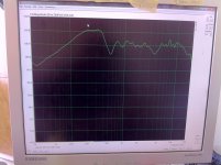
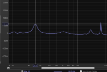
So what can a sound card and REW do for you in terms of audio distortion measurement? Here is a typical FFT spectrum that I took using a $99 Focusrite Solo USB sound interface and REW with the Alpha 20 amp. This is 2.83vrms into 8ohms:
The plot above tells us several things about this amp: it has a dominant second harmonic distortion signature (sweet sounding), it has a little third order (gives it some bite), it’s devoid of higher orders, or higher odd orders specifically, which can sound fatiguing; it has an overall low level of total harmonic distortion (as seen in onset window); the mains noise at 60Hz and 120Hz is essentially zero - that is, it is very quiet and hum free; finally, the noise floor is about -110dB below the signal so it has very black blacks.
How hard is it to take this data? Well that’s the purpose of this thread. To show you how easy it is to do.
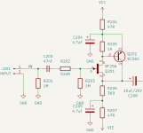
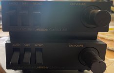
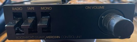
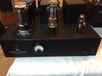
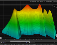
Another example of how REW can tell you how to tune your amp to achieve a harmonic distortion profile of interest. Some amps have this variable knob that lets you tune the type and level of distortion to your liking:
DLH Amplifier: The trilogy with PLH and JLH amps
Here is an example of measuring a preamp driving a 7k ohm load, this is the Aksa Lender putting out 20Vpp into 7kohms:
So where to begin? Let’s start with getting a copy of REW on your computer. Works on PC or Mac but I am only familiar with the PC version. Go here to download REW, and while you are at it, please donate some funds to John Mulcahy to continue his excellent work.
REW - Room EQ Wizard Room Acoustics Software
Once you install it, install software or drivers for your sound interface. I have used even the built in sound card in a PC to do this and it can work. However, those are generally very noisy and you won’t get the nice -130dB noise floor that some standalone interfaces can achieve. I personally use a Focusrite Solo (2nd gen) and 2i4 (2nd gen). They both have the same ADC’s but the 2i4 has a front end that is more flexible. I also think it has slightly better low noise characteristics. But you can use any sound card as long as it is supported by REW - and that includes any Java supported card. I haven’t found one that is not supported yet.
Next step is to connnect your interface by plugging in the USB cable, for example. Some of you might have other interfaces. The go into the setup menu and configure the sound interface. I typically the non-ASIO interface as I find that more finicky to work. Then choose your input device as your sound card and your output device as your sound card. Choose input and output amplitude to be “Master” and set to amplitude of 1.0 - this lets the full signal be generated by the sine wave generator and the full signal be captured by the ADC.
On the input settings choose the channel where you will connect your amp’s load resistor. Channel 1 is typically the “Left” channel and channel 2 is “Right”.
At this point you can see what the inherent self noise of your sound interface is without anything connected. Click on the “RTA” button along the top. In this dialog, click on the gear to adjust the settings. I use something like this:
You can try other settings. Making the averages smaller like 0.88 exponential and choosing 32k points will give you almost real-time updates to the FFT. You need to click on the span button to set your range of measurement from say 20Hz to 20kHz. On the vertical scale button on upper left click on dBFS. Then click on the red button to acquire your FFT spectrum.
You will see a relatively flat spectrum (hopefully) but this will tell you what the noise floor of your setup is. A cheap built in sound card on my pc only gets -110dB. The Focusrite get -130dB. There are ways to achieve better noise floor and much is discussed in threads elsewhere. For many of our SS amps around here the typical noisefloor of the Focusrite is fine as distortion is typically no lower than -100dB abd typically -80dB or so.
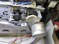
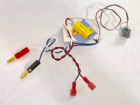
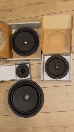
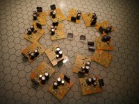
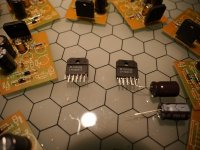
This is all fine and good but how do we measure distortion in our amps? Well we first need to make a dummy load resistor to simulate your speaker load. You need a power resistor with the same impedance as your amp that you are testing. Typically 8ohms or 4ohms. It also needs to handle the amp’s power output. A good one is a metal shelled 25w resistor mounted to a heat sink.
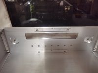
Here is an example of one with the wires you will need to make to connect it to a sound interface:
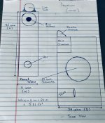
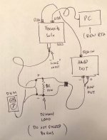
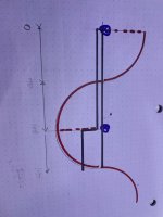
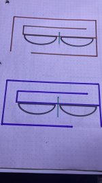
Here is a sketch of how to connect your load resistor to the sound interface and the PC:
For measurements of amp power up to 1w (8Vpp) it’s ok to connect the dummy load to your sound card directly. However, if your amp ever had a burp and hits the interface input preamp with too much voltage it can fry the input stage. I would recommend adding a ~10:1 voltage divider using a 20k and 2k resistor and taking the middle node attenuated output as the signal to your sound interface.
Edit May 10, 2024: circuit for floating balanced input needed for bridged class D amps here
https://www.diyaudio.com/community/...ion-measurements-with-rew.338511/post-5925805
Also, if you are using Class D amp, you need a steep filter to keep the high frequency noise out while not distorting the low frequency to prevent aliasing the data. I used the filter suggested by Voltwide/Bucksbunny here:
https://www.diyaudio.com/community/...ion-measurements-with-rew.338511/post-6714709
Depending on your sound interface, they may be good for 20v max input so that would give you pretty good protection. Never put full 25wrms (40Vpp) into your sound interface unless you want to fry it.
Now you need a way to generate your 1kHz (or whatever frequency you like) excitation sinewave. You can use the audio output of your sound card and the built in generator in REW. Then connect the audio out of the sound interface to your amp’s input. Adjust the level using the amp’s volume knob if you have one or the knob built into the Focusrite or the level in the generator interface.
Another way is to use an independent reference frequency source. A dedicated low noise high precision generator from HP is expensive. You can use a digital audio player with a good DAC as your source. I use a Cayin N3 which has the excellent AKM4490 DAC. Create a 1kHz sound file in lossless flac format using a program like audacity. Then play that into your amp as the excitation source. Those has the benefit of decoupling your source from your measurement to avoid ground loops. Especially if the source is a battery powered DAP. It’s also typically quieter.
So now connect your audio source to your amp, connect your amp to your dummy load, connect your audio interface to the dummy load, and connect a DVM to the dummy load and set to AC volts. Increase or decrease the amplitude of the 1kHz sine wave until the DVM reads 2.83vac. That’s same as 1w into 8ohms. A typical standard at which distortion measurements are taken.
That’s all for now. I will update later as I did this post with my phone and will get back with more details. But this should get many of you started.
Update June 3, 2019: Here is a loopback using Focusrite Solo gen2 and Akitika 2ppm 1kHz oscillator at 1.0Vpp into 10k:
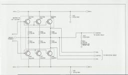
Update Sept 24, 2020: member
Wtnh made a very nice and useful schematic and connection diagram for us to use. Although he used an EMU sound interface, a lot of it applies to other sound interfaces as well (like Focusrite, or any other with combo XLR/TRS balanced inputs):