high gain contact mic preamp

Hi all.
Could you please give me some guide line for making a preamp with variable gain (60db or if possible 100db) with relatively accessible parts?
I was able to achieve a fixed 60db preamp with simple parts and dual 12v supply (with +-12v) and inspired with this project. sorry if it seems noob.


Screenshot from 2024-04-05 11-20-31.png


Now the problem is i now have a single 5v supply instead of dual ±12v.

Martin Logan 2nd / 1st gen CLS harmonic distortion?

It's been shown in several measurements by different people that Quad ESL63 can have very low distortion. Final ESLs have a reputation of having poor harmonic distortion either because they use an unusual drive configuration (inverted electrostat) or because they used to use high conductivity membranes. The example of a more recent Final ESL I found a review of pretty good, though:

https://www.diyaudio.com/community/threads/inverted-electrostat-inferior-in-distortion.409322/
Just one picture (ignore the 0.5% THD which is probably THD+N, the important thing is that the HD2 is 60 dB down = 0.1% HD2)
1712931994877.png


I also had a chance to measure an Acoustat 1+1 recently. I just did a quick test at 200 Hz at rougly 85 dB / 1 m and got HD2 about 55 dB down, so not bad at all.

There were also measurements of pre-production Capaciti panels in Klang+Ton and HobbyHifi magazines which were in the 50 dB+ range.

Well, I came across this review of the purity which has a Gen 2 CSL panel (same reviewer & magazine as the Final review, but different equipment and parameters):

https://hometheaterhifi.com/reviews/speaker/floor-standing/a-secrets-speaker-review15/

1 kHz distortion at (guessing from full FR sweep further down in the articla 87 dB / 1m ) is poor at 1.36%, this time stated as THD+N. More importantly, the HD2 is only about 37 dB down.

1712931726340.png

https://hometheaterhifi.com/wp-content/uploads/2015/08/martin-logan-purity-speakers-1-khz-large.gif

That number, however, is not consistent with THD+N sweep which should be higher because of the noise included and reads more like 0.6% at 1 kHz:
1712931657296.png

Even at 10 kHz, still 0.24% which is high for an ESL
1712931780512.png

Even the integrated ICE-T amp can't be that bad. So is anyone aware of reviews or other published measurements of Martin Logan ESLs? Is there a chance the Gen. 2 with their metallic coating and clear plexiglass spacers / dampers perform worse than the Gen. 1 with graphite coating, heavier foil and foam dampers?

LM1876 mute pin delay circuit in LTSpice

Hi all,

I am currently working on implementing LM1876 based amp and ran into the issue with the mute and standby pins.

From the datasheet, if a logic high (1.5 to 5V) is applied to the MUTE pin, the amp will be muted.

The goal is to mute the amp during the turn on (and turn off).
For that a logic high needs to be applied to the MUTE pin when amp is turned on, but after 1 or 2 seconds wait time the MUTE pin should be pulled low (< 1.5V).

I have come up with a simple simulation circuit that consists of :
  • 5V zener regulator
  • RC time delay
  • NOT logic gate

Power is taken from the positive rail of the amp's power supply that is 20V to 25V.

Zener regulator resistor is selected at 1K, and it pulls about 20mA of current.

Any suggestions on improvement will be appreciated.

Attachments

  • sch-mute.PNG
    sch-mute.PNG
    15.4 KB · Views: 212
  • responce_at_mute_pin.PNG
    responce_at_mute_pin.PNG
    15.3 KB · Views: 190
  • time_delayed_NOT.asc
    time_delayed_NOT.asc
    1.9 KB · Views: 102

Denon AVR 1306 protect fault

Hello,
Does any one know what are all the reasons an AVR would blink a red light for? I'm not talking about obvious reasons here like an output short, I need to know all the causes because seems like my AVR has some issues going on so I want to check every possible reason (A guide to which pins to check is appreciable)
It worked awesome for the last 10 years but a week ago it burned a capacitor (which I changed) and problems started cascading. I did everything I could do but now I'm stuck with the blinking light
Here is a list of things I tried:
Checking spk output for short
Resetting the AVR
Checking supply rails (all of regulators are within a tolerance of 5% or less)

OB design with SB Acoustics SB20FRPC30-8 or similar

Hi guys

I would like to experiment with open baffle speakers on the cheap and was thinking of building one using the SB20FRPC30-8 which I have installed in my car and was really impressed by it.

The plan is to have the speakers eq'ed (if needed) to reach moderate levels below 80hz and then crossed them to by subs.

Would you be able to offer any guidance regarding driver selection, baffle size (if possible to be minimal and short) and expected bass response based on xmax? I don't know how to properly simulate this.

Thanks!

Looking for insulated turrets

I'm looking for some insulated turrets, preferably with inside thread mounting like this one:

https://eu.mouser.com/ProductDetail/Keystone-Electronics/11512?qs=do/%2B0R7m72eYwljRf/eNuA==

Mouser wants $ 15 for each which is more than I want to pay. Someone has a bunch laying around they no longer need?
I need about 2 dozen.

Jan

Attachments

Oppo BDP-103 won't turn on

Hi! I had a lucky find at Seattle Goodwill - Oppo BDP-103 for $24.99.

When I plug it in the tiny light on the far left of the front panel glows red but other than that the unit is completely unresponsive. No other lights come on, no sounds of moving parts. Pressing power button does nothing.

I opened it up to look for obvious signs of damage and didn't see any...no bulging or leaking capacitors, no water damage, no scorch marks etc.

Any ideas on what might be going on? Thanks in advance! -Joe

For Sale Several lateral mosFET amplifiers (PeeCeeBee, Holton, Sigma) + Power Supply

All SOLD

This year I thought I was going to build something I was trying to for a long time, a multi amplifier with lateral mosfets, so I bought a buch of lateral amplifiers in the forum.... but the fact is that I don't have time to build a nice amplifier. i have tested them and they sound awesome. In a direct comparison to Goldmund Job I have to say there is just a subtle difference... if any, but the friend who let me the Goldmund Job will sell it to me at a ridiculous price and it will save me very much time to buy a finished amplifier than building it, so they will go for sale priced to be sold trying to recover part of my investment. All of the amps has been tested, adjusted and in perfect working condition.

2x Holton Precision HPA NXV200L 4.1 with 1 pair EXICON mosfets each: Asking 200€ for both. (Priced each at 165€ at Holton web)
150 Watts RMS 8 Ω at +/-63VDC rails
270 Watts RMS 4 Ω at +/-63VDC rails
Driver stage can be feed regulatd or unregulated

2x SIGMA reference class audio amplifier with 2 pairs of 2Sj1058/2Sk162 each board. Asking 260€ for both.
180 Watts RMS 8 Ω at +/-68VDC rails
220 Watts RMS 4 Ω at +/-68VDC rails

2x PeeCeeBee V1.1 amplifier with 1 pair of 2Sj1058/2Sk162 each board. Asking 60€ for both.
80 Watts RMS continuous sine wave into 8 Ω can be run from +/-15V up to +/-35V
100 Watts RMS continuous sine wave into 4 Ω can be run from +/-15V up to +/-35V

Prices + PP fee + Shipping.

Any question, offer or whatever, PM me.


Holton Precision HPA NXV200L


SIGMA reference class audio amplifier


PeeCeeBee V1.1 amplifier

Tangband W8-1808 for Acousta cabinet?

Hi all,

first off I would like to say that DIY Audio is really great filled with many great people. I’ve spent the last few weeks reading about how I should approach doing my own BLH.

it started with auditioning a pair of acousta 115s….then going through the Alfredo horn threads. I thought I was set on building the Alfredo horn with Tang band W8-1772 only to learn that the bass rolls off at around 60Hz. While the Acousta would reach 40Hz.

I’m not a big fan of Lowther drivers…..so I thought of replacing it with the W8-1808.

Could anyone give their opinion on this?

TO-3 to TO-252 Adapter PCB

I designed a TO-3 to TO-252 adapter PCB to upgrade an amplifier I have from obsolete MOSFETs. I wanted to post it here to gauge interest from the community. I'm willing to sell these as a kit with pins or pre-soldered. Price TBD but will be reasonable.

The board has thermal vias under the TO-252 tab for heat transfer to the bottom ground plane which is exposed copper with no soldermask.

ezgif-7-570773277e.jpg

Attachments

  • ezgif-7-12e9483c38.jpg
    ezgif-7-12e9483c38.jpg
    71.5 KB · Views: 120

XP-10 "gain" setting? What is this witchcraft?

So I maybe found an easter egg, or at least an undocumented feature of my XP-10. Fiddling with buttons while listening to my usual 90's proto-grunge trash, I found this setting called "gain", and turned it on. It made the almost-clone-of-the-ACA-Mini I was using for amp duties sound quite wonderfully chunky and thrusty. What even is this?? 😍

Attachments

  • IMG_9957.jpg
    IMG_9957.jpg
    370.3 KB · Views: 112
  • IMG_9958.jpg
    IMG_9958.jpg
    407.2 KB · Views: 115
  • IMG_9959.jpg
    IMG_9959.jpg
    409 KB · Views: 118
  • Like
Reactions: Dennis Hui

Simple DAC for LinkPlayA28/31

I am trying to build a wifi airplay module for Airplay as of now. Though the Linkplay modules can do much more and can possibly replace Moode / Volumio / PCP on Raspberry pi.
So my challenges are the PCB design and selection of DAC chip. I still do not know if the Linkplay board will play the game or not as PE does not share much info on it. But since the cost was $10, I could not help picking one up.

So Far I have been able to connect the link play module to my local wifi and have my iPhone play connect to it like an Airplay Device and the phone transfer's the audio to it.
I am also able to send API get-command to it check what is playing on it and change volume - this works.

LinkPlay Module has I2S audio out of about 24bit / 192kHz.

Also, the I2S pins are BCLK, LRCLK, and DATA_OUT. Only MCLK is not provided.

The Biggest Question that arises is which DAC and how to connect

PCM5102
ESS9023
?

this is the schematic i have built so far - the Resistor the output of the Regulators is going to be chokes and not resistor, its a place holder
1659259853959.png

Rockford Power T600.4 Channel offset

Good evening.

I'm working on a Rockford Power T600.4. The repair seems to be good. Biasing is done... only problem is, the front and rear left channel is 4.5db louder than the front and rear right channel.

I haven't messaged Rockford about a schematic yet. Was wondering if anyone else has had this issue before?

Attachments

  • 20240411_192948.jpg
    20240411_192948.jpg
    569.7 KB · Views: 77
  • 20240411_202707.jpg
    20240411_202707.jpg
    517.4 KB · Views: 69

Sprague Vitamin Q L96P code?

Hi folks,

I've been sorting through my caps and came across these- Sprague Vitamin Q caps with a prefix "L". The code is L96P.

I have never seen that "L" prefix before, nor can I find any info about it.

I'm familiar with most Sprague codes (91P, 96P, 191P, 196P, CP08, 260P 118P, 160P, etc...) But this has me stumped.

96P is inserted tab construction; 196P is extended foil construction. Ultimately, I'm trying to identify the construction of L96P.

Hope someone can help! 🙂

Thanks, Kent

Attachments

  • IMG_1716 copy.jpg
    IMG_1716 copy.jpg
    197.6 KB · Views: 54

Zaphaudio ZD5 still worth it... MOD advice ...

Hi Folks
I am looking for a reference level speaker to build for a small room and I am interested in the Zaphaudio ZD5 floorstanding vented enclosure.
Since it is an old design and most of the info I find it's also old I wonder if it is still a good choice or I should be considering other options.
I also checked the Troels Revelator-51 and Ellam 9800 but I am not sure if the bass response is on pair to ZD5.
Please, I would appreciate some advice!

If I decide to build the ZD5 I would like to make the enclosure less deep using part of the sand filled chamber at the bottom. Total volume and front baffle would remain unchanged. Approximately something like this:

Internal dimensions inch(cm): Width x Deep x Height
ORIGINAL: 5.5(13.97) x 12(30.48) x 23(58.42)
MOD: 5.5(13.97) x 9(22.86) x 30.5(77.5)

Is this a bad idea? Other dimensions would work better? Port can remain in the same position?
I read that lots of additional damping will be required at the bottom
Please I need guidance from expert guys!! Thanks!!

Renkus Heinz SSD3301 too loud

Hi guys,
I have a pair of 3301 with JBL 2226HPL 12-inch woofers but my issue is that the 3301 are too loud compared to the woofers. I tried applying an EQ on my master out from the console but this isn't the best solution. Could be too loud because of the crossover design? As far as I remember the crossover PCB I have inside the speaker is extracted from another speaker with different specifications. Can anyone give any suggestions? Should I replace the crossover PCB with something different to reduce the volume or do I need a resistor in series to achieve this?
best regards

Horn Extender/Wave-guide for TH

My (former) mains PA uses rather small horn top cabinets, only 26.5 inch wide. The sealed conical expansion FLH (front loaded horn) response drops below 200 Hz, but using fourteen 8" drivers per side makes the response OK to around 70 Hz. When I need a bit more low end and directivity I use wave-guides in front of the stack, it gives the low end of the horn a 3 dB boost down to around 70 Hz, and maintains the 90 degree pattern down pretty low.

In front of the Keystone TH (tapped horn) cabinet, the wave-guide increases SPL (sound pressure level) by an average of 3 dB over the entire sub-woofer pass-band from 36 to 100Hz.

The wave-guide adds SPL to any LF (low frequency) enclosure by increasing forward directivity.

The wave-guides in the photos below are constructed from four pieces (top and bottom, left and right sides), and break down to a package about 6" (inches) x 20" x 54.75". Ratchet straps are used to attach the four parts, and to attach the wave-guides to the mains cabinets. There are no rattles even at the full peak power of around 6600 watts per stack. Since the wave-guides couple a larger area/volume of air in front of the stack, SPL in the immediate vicinity directly in front of the stack is actually lower than without the wave guide.

The wave-guides take a few minutes extra time to set up, but considering the cost to output level increase they afford in a small cargo space, the equivalent of doubling speaker cabinets without paying for the second set is quite worth it on gigs that need a lot of SPL using the minimum amount of power.

To sum up, the advantages of horn extensions and wave-guides ("barn-doors") are several:

1) Some venues are simply too small to use a really large horn in.
2) Horn extensions can be made to nest like Dixie cups, as did the Community "Leviathan" horns from the 1970s, or can be made in four parts, like my 1977 (or 1978?) exponential FLH "Collapsable Crunchers", or the wave-guides described from this century. Any of those approaches can reduce the transport volume by as much as 90% compared to a single horn of equal size, but do require more set up time, construction is more difficult, and some extra hardware is required.
3) The two "tunings" (Fb or Fc) afforded allow a horn extension to be left off if program material does not require the extra LF (low frequency) extension. That said, a cabinet designed for horn extensions may be a compromise in either configuration, especially in TH compared to FLH designs.
4) Wave-guides can add 3-6 dB forward gain with no power compression, drastically reducing power demands for a given SPL compared to the same cabinets without, and require no special design consideration regardless of cabinet design- they work equally well on BR (bass-reflex), TH, or FLH. The bigger the wave-guide, the better, for more forward gain and reduced rear "wash", while also reducing SPL in the immediate near-field directly in front of the cabinets.

Some wave-guide construction details are in post #40.
An example of a rather ineffective TH extension is in post #9, and a far more effective TH in post #49.

Art

Attachments

  • Horn Extender.jpg
    Horn Extender.jpg
    23.1 KB · Views: 5,457
  • TH Extender.png
    TH Extender.png
    39.7 KB · Views: 5,349
  • C Horn &THwEXT.png
    C Horn &THwEXT.png
    98.7 KB · Views: 5,296
  • Like
Reactions: freddi

Inverse RIAA circuit with simulated MM cartridge inductance

I put together a little test box which is a two channel inverse-RIAA network / attenuator including a simulated MM cartridge to give more realistic noise response:

Screenshot 2024-04-11 at 22.37.04.png


The actual unit has the inverse RIAA network switchable so a flat response can also be obtained. At 1kHz the MM output attenuation is 40dB, the MC output attenuation 60dB.

inv-riaa-front.JPG
inv-riaa-back.JPG


The inverse RIAA response for the two outputs:


inv-riaa-atten.png


Slight peaking from the inductors is evident. I didn't quite meet my design values of 40dB and 60dB attenuation at 1kHz but its close 🙂

When used to test one of my phono preamp designs I measured the THD against level of the combined system:

inv-riaa-into-tonearm-riaa-lev.png


I was worried the inductors might be adding distortion but it seems to be noise limited until the headroom runs out.

I've not seen the concept of including a model of the cartridge in such a network - I mean to graph the noise spectrum at some point (its best to do this far away from mains electricity for a cleaner trace).

The sort of plot I expect is this: (from another breadboarded test circuit)

OPA1652-500mH.png


as opposed to the more commonly seen:

OPA1652-0R.png

Attachments

  • Screenshot 2024-04-11 at 22.54.25.png
    Screenshot 2024-04-11 at 22.54.25.png
    19 KB · Views: 90
  • Like
Reactions: alighiszem

Anybody Using a Hagerman Vacutrace?

Just got one. Looks fine. Manual is really thin on detail. Not sure if this thing is working or not. Powers up but can't see how to adjust parameters like plate and grid voltages. It's like this is a guick-start guide, but no, it's the manual. It says to make adjustments for set-up, but where do they appear? The LED is only operative in Hold mode, but initial settings are done in Sweep. One good thing--it is talking to the scope. Appreciate any help.

Audio Precision ATS2 (ATS-2) calibration

I am currently reworking my ATS2. Since I haven't found an official calibration procedure I'm starting this thread, maybe someone is interested in exchanging ideas.

The first thing I did was to replace some faulty AD797 opamps (got incredibly hot and caused very high THD values). I have also replaced some caps. Now all values are okay. Nevertheless, generator B produces much higher THD values than generator A when the system gets warm, but they remain just below the specs.

I was able to identify the effect of most of the trim pots by trial and error, I will try to summarize the results here later. Does anyone have any idea what the pots circled in red in the picture are tuning

I hope someone is interested as well.

Best regards

Attachments

  • Bild1.jpg
    Bild1.jpg
    554.7 KB · Views: 286

TPA3255 custom board overload problems

Hey Folks,

I have been a happy user of my custom made TPA3255 boards for years now and still am, despite a recent incident at high volumes🙂

I have a MCU in the front end that detects clipping/error conditions and lowers the volume when clipping or any kind of overload occurs. I am using them with two 20V 170W Lenovo power supplies that are stacked up for 40V DC output. The amp is configured to run in stereo BTL mode, which is meant for loads from 4-8ohm. PVDD capacitors are two 1000uF 50V Panasonic FMs.

When testing the amp at a friend's place on his B&W 703 S3 I finally pushed it a bit harder and it did overload at some point - clipping was detected and volume was lowered as expected by MCU. However, on few occasions and before clipping was detected a loud cracking sound occurred, like there was a hard cutoff at the output - not a very pleasant thing to hear as you can imagine. I was not expecting this, as I was hoping that any error conditions would be caught by internal circuitry and errors raised to be handled by MCU.

Now, I know that according to specs, 8ohm 703S3 can go as low as 3.1ohm at some frequencies, so I am wondering if this was maybe the culprit? Or maybe the PVDD capacitor bank is not big enough, seeing that eval board is using 2x4700uF? According to the datasheet, if OC protection kicks in, the device will go into error state which needs to be cleared by _RESET.

Any ideas what could be causing this kind of behavior?

CMoy-inspired Headphone Amp For Novice First Build

What should a DIY-Audio novice build first. The WWW has suggested the famous CMoy headphone amp as a good novice project but I think we should construct a few projects that are easier and more robust for the novice. The following is my effort to offer such a project which I hope the novice will find buildable or interesting.

(Newbie, newb, noob, noobie, n00b is a slang term for a novice)

Legacy Projects: CMoy is a portmanteau of Pow Chu Moy who created a minimilist headphone amplifier that people could build with parts from Radio Shack. The original was in a plastic box with an opamp and a battery. It had a high-low switch for volume control. The HeadWize site showed many variants especially the Altoid Tin version. Mr Moy has passed away and HeadWize is gone but someone created a memorial site without the lost forums. [Memorial]

Next, there is the comprehensive tutorial provided by Tangentsoft [Audiologica]. It suggests that the CMoy pocket amp is an excellent choice for your first DIY audio project. I agree except that the tin can enclosures and rail-splitter power supply are not required for a desktop unit.

Prerequisites: You need to do soldering, drilling, and multimeter measurements. You need to have keen interest in doing it.

Shopping: You need to satisfy the Bill of Materials (BOM). Most parts are from Mouser. There are a few items from Amazon.

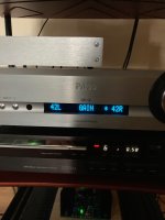
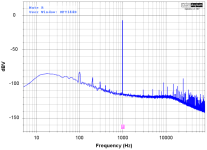
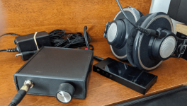
System: Here are two images showing the completed system recently tested. The front panel 1/4 jack connects AKG K702 headphones. The K702 demands more drive for it's 62 ohm impedance. It is not a problem for this single opamp JRC4556AD in single-supply mode. The power supply is Triad 15vdc. I did not test with 24vdc which is not required. The back panel has a DC jack and two single RCA jacks for input from the FiiO line output.
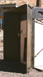
amp-front.png
amp-back.png

Enclosure: The enclosure is a Hammond Box with standoffs for 2 BusBoard Systems size1 PCBs. This box has removable front and rear panels for easy drilling. This project uses panel mount jacks and volume pots. Panel mounting requires a bigger box but does not require the precise panel measurements of an integrated PCB.

The selected Hammond Box has room for two size1 PCBs or 1 PCB which can be in 3 positions ... front, center, or back. With one PCB only, the box has more room for panel mounts. There are six standoffs in the base and 4 more in the cover.

PCBs: Busboard has 3 types of size1 (80x50mm) PCB. There is stripboard, proto board, and PadBoard. PadBoard is best since it is double-sided with plated-thru holes. Solder flows into the thru-hole such that a good connection can be made without solder blobs. And it is easy to desolder cleanly. Only the PadBoard has a square pad every 5th hole for easy placement of parts in 31x19 holes. I provide a layout plan to visualize the end result before starting installation.

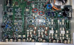
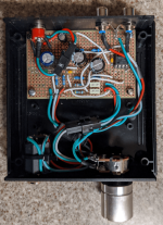
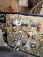
Top View: Here is the Amp with the top cover removed. It reveals a few flaws caused by all the standoffs. The PCB is in rear position to leave more room for the front panel wires. The PCB can be in the center positon if smaller wiring is installed. The volume pot needs to be installed closer to center so that it can be rotated to feed shorter wires along the side. The phone jack needs to be closer to center because the cover has standoffs for a size2 PCB. The cover can close but it rubs the phone jack a bit.

My build has flaws or bugs but the plan is updated to resolve them.

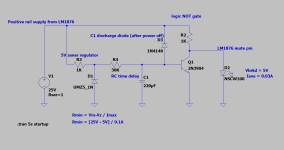
Schematic: This first build does not include an integrated power supply. Instead it is biased for single-supply operation so that a 15vdc wall adapter can be used. D1 protects against accidental reverse-voltage. D2 indicates when the unit is active. R2 and R3 provides 7.2vdc for opamp bias. C7 and C8 protects the headphones against DC voltages. There is a special power-on procedure to prevent noises from capacitor charging. Wait a few seconds before connecting headphones. The caps will charge through R10 and R11.

Mr Moy advised CMoy builders to use disposable headphones since they are not protected in the minimalist rail-splitter (virtual-ground?) design. TangentSoft has a whole page explaining virtual ground variations. Given all the explaining, there is no way to make it robust. And novice projects need to be robust.

head-amp-small.png

PCB Plan: The PCB is modelled with VeroRoute (VR) as a 1-sided unit. The connections are routed automatically but constrained. For example, VR Tracks cannot cross each other but VR Wires can. IC1-1 connects to C7 and R9 via a purple VR Track, which is a bare wire on the PCB underside. IC1-2 connects to R9 via a pink VR Wire which crosses the IC1-1 VR Track (an insulated wire on the top side). There are no tracks on the PadBoard, connections are physical wires between the component pins.

Sometimes VR will take an awkward route as it recursively searches for a good path. In that case, I add labelled pads or VR wires to guide it to a preferred path. At other times, the autoroute is too complex making the plan hard to read. For example, IC1-5 needs to connect to C6-R5. There is no connection in the PCB model, just U5 labelled pads. The connection is completed by adding a top-side insulated wire U5 to U5. It's easier to use this hybrid approach.

There are gaps between components for ease of soldering without creating short circuits. The circle-X symbols are non functional. I use them to mark pads that should be reserved.

amp-plan1.png

Stuffing: Components are added to the PCB in phases. Phase 1 includes soldering the resistors and other components in their planned location. They should be lightly soldered on the under-side such that resistor leads are straight and cut short less than 5mm. These short leads are posts for the connecting wires. The PCB supports are 5mm. So install all the components to complete phase 1.

Phase 2: The under wires are installed in phase 2 where the component pins are wired according to the plan. Since the DIP socket has short pins for installation on a fabricated PCB. the PadBoard requires a custom procedure for the DIP. Insert a bare wire top-side, switch to the under-side and bend the wire to form an "L". Next, retract the wire until the end is flat on the PCB and touching the DIP pin. Solder gently. If this seems strange, you can try making a hook around the pin instead.

Use a temporary wire twist to hold the DIP in place for soldering.

under1.jpgunder3.png

Phase 3: The top-side insulated wires are installed in phase 3. These
are not shown in the plan. Here is a list.

U3: F5 ~ D14
U5: L4 ~ B14
U8: M8 ~ J21
!U4: J9 ~ R17
U4: C8 ~ H23
H1: H13 ~ C21
H2: I17 ~ C23

top1.jpg topview1.png

The BOM is attached. It is in Open Data Format.

Attachments

  • BOM2.ods.zip
    BOM2.ods.zip
    34.4 KB · Views: 73
  • amp-front.png
    amp-front.png
    456.3 KB · Views: 101
  • opened1.png
    opened1.png
    233.5 KB · Views: 89

Open Baffle In A Small Room? [Advice please]

My listening room is 10 x 20'. It will be for high-end, 2-channel listening and for home theater with a 65" screen. The speakers and screen will be on the 10' wall. I am considering open baffle speakers, preferably a full-range driver or co-ax point source. Is this room too small for open baffle? Am I better off with a single, point-source driver in a small cabinet? I will be using three subs.

Output Transformer Primary Winding - Calculating the Inductance.

Really struggling with this one. I've read Radio Designers 4, Wolpert, Poppovitch and other source material, non the wiser. Could someone tell me what is the equation I need & what are the various parameters I need to know please?

So far I've figured out Vpri & Ipri, Vsec & Isec and Lpri of a 25W PP OPT with a Zpri of 4k & Zsec of 8r. I figured I'd need an L of 63.69 for a 3dB loss or 127.38 for 1dB. I then pulled a load of spec sheets for "typical" laminations. This is where it gets tricky. I have 4 sets of laminations with bobbins, one set I know is Goss, the others, Bog knows. All lams are about 0.3mm thick. The only other spec I can find for a UK supplier of Cores is "thickness 0,35 mm, 50 Hz, 17.000 Gauss" or 1.7T: not much to go on.

So how the hell does one work out how many turns one needs on the pri to get L whatever with laminations of Bog knows what type of steel? Is there a rule of thumb?

Andy.

Desktop speakers with wide-range driver

I'm heading towards my next build for a pair of stereo desktop speakers. Crossover points will be established through testing, but there is a fair chance that the final decision would be considered a wide-range assisted design. At least, I'm intending to use a "full-range" driver as a wide mid-range, or beyond. So in the absence of clairvoyancy I'm posting here.

The drivers I've chosen after some testing are the Alpair 7ms and SB23MFCL45. The former will go to below 80hz at -6db in a 5L sealed box - though I intend to high-pass them as part of an (active) crossover, and might also try a tapered aperiodic design. The latter are technically called subwoofers but only have a 6.5" effective cone diameter and will go up towards 200hz, which seems high enough for woofer assistance (my aim is stereo, not a sub+sats). They'll reach down to about 37hz at -6db in a 23L box, which is pretty much what I want (though they could go lower with EQ if wished; I'm listening at less than 1m, so am not needing massive SPL/excursion).

These 'may' be joined by a pair of 19mm SB tweeters crossed at several khz or more, but I've not decided yet. I'm not against tweeter-assistance, and in testing I do slightly prefer their contribution. However I have old enough ears that their benefits are fairly small over the 7ms alone, so I might not bother with tweeters at all. We aren't very sensitive to a lot of subtleties at very high frequencies but even so, achieving properly good integration (including stuff like controlled directivity) would be reasonably involved.

Cowen tapped horn modified...

Hello,this is original cowen horn folded for 12 inch,,,

gefaltetescowanhornfyk.jpg

I own two C/E/X pa flat to 30Hz with 18inch eighteen sound 18NLW9000 which i like soundwise ,but i found i don`t need the headroom in my hifi system,,,

So eventually i made a test cowen horn and modified bit to fit eighteen sound 15sw 115,yes i did calculations in hornresp but more for

backing up my thoughts,mainly i pushed some wood around and made measurements,,,,

I`M listening the modified sub for half year now and for me it plays well,deep,and enough power for home use 🙂


Maybee someone can use this info...

so here modified version,,,
DSC_0871.JPG


yes
DSC_0872.JPG


Yes I´m german so only metric 🙂

here measure of FT30


DSC_0868.JPG
s
brown is 0-meter 20-50Hz (mic direkt horn exit)

blue is 0-meter 20-100Hz ""

cyan is 1-meter 20-50Hz mic 1-meter from horn mouth ground plane


lets see what 15inch cowen modified does

DSC_0867.JPG


same measure

red 20-50Hz 0-meter mic at horn mouth

blue 20-100 0-meter

green 20-50Hz 1-meter mic one meter ground plane


lets compare


DSC_0869.JPG


brown is ft30,red modcowen 20-50Hz mic direkt horn mouth


DSC_0870.JPG


cyan is ft30,green is modcowen mic 1-meter grond plane,yes room modes but comparabel,,,,,


test box modcowen is 18mm chipboard vibrating like hell ft30 is well build lots braces from plywood

so should improve when build right

modcowen is prx:370Liter

ft30 is :595Liter

mod cowen not so bad compared and lud enough for home use,,,

measurements are not spl calibrated,,,

have a nice day

SB-6 Technics speakers cabinet re spray re store - lifted woofer surround on one side

I am currently restoring my SB-6 cabinets - sanded and filled the corners with filter - then a primer spray and black satin finish

Taking the speakers, they were quite set in their place - my previous paint job ( wasnt pleased with it)

I took the plastic surround off one woofer without issues and then damaged the other as per photos.

The material looks like cardboard or some compressed paper onto metal.

What would be the best adhesive glue? assume one with flex?

Thank you Sam

To save making another thread, I noticed Rust-Oleum paints have a paint/ primer. I am thinking though being particle board, its best to use a primer and maybe their 5in1 Satin black, as ive used the 5in1 and it has a nice low output setting etc. I worry using spray paint as dont want another bad finish lol.

https://www.bunnings.com.au/rust-ol...-ultra-cover-paint-prime-spray-paint_p1580677
Rust-Oleum 340g Canyon Black Satin 2X Ultra Cover Paint+Prime Spray Paint

https://www.bunnings.com.au/rust-oleum-340g-grey-flat-2x-ultra-cover-primer-spray-paint_p1580683
Rust-Oleum 340g Grey Flat 2X Ultra Cover Primer Spray Paint


https://www.bunnings.com.au/rust-ol...rust-custom-spray-5-in-1-spray-paint_p0489935
Rust-Oleum 340g Satin Black Stops Rust Custom Spray 5 In 1 Spray Paint


P1520759.JPG

above lighter shade where it ripped up some of the surround - note the right hand corner of some of the surround

below - the plastic surround was glued to the surround - other woofer it came off without damaging the surround.
P1520749.JPG


its lifted as per photo

P1520761.JPG

Passive Radiator things

For starters, thoughts on price performance things. I find that decent PR units can cost more than the active driver, in some cases. One that I am messing with is a $100 driver and the PRs come in at $65 each with 2x needed. Is nailing the targets justification enough to spend so much on "ports" or is that money better spent on optimising a dual active driver design? Such are today's pondering while perusing online shopping carts on what to pull the triggers on 🙂

5 way horn speaker system project - tapped, bass, mids and tweeter passive active

It all started out with my making a pair of Tannoy GRF replicas and liking that sort of sound.

It ended up with a full 5 way horn system, evolving and my learning lots along the way.
A long way from Tannoy Dual Concentrics in scale, dynamics and detail.

Pictured in 2023

IMG_20231005_111205~2.jpg


2015

Screenshot_20231026_102951_com.google.android.apps.docs~2.jpg


The journey was From big conicals to a mixture of Le Cléac'h, Tractrix, Exponential, and of course the thunderous yet tuneful Tapped sub bass horns.

It all started when I first heard I_Should_Coco's (yes, he has a lot to be thanked and cursed for🙂 ), AH-300 conical horns with Vitavox S2 drivers and my making a pair of conical horns.. and crossing them at 1000Hz using Tannoy HPD's as bass in my birch plywood GRF cabs.

Under construction.

Screenshot_20231006_190557_com.google.android.apps.docs~2.jpg


Then complete.
Screenshot_20231006_191009_com.google.android.apps.docs~2.jpg

I used JBL2435Be's.
1.5" Beryllium diaphragm modern compression drivers.

I'd heard good things about them and they were not that expensive... Sounded pretty good to be honest!
I had to import them from the USA. They were not directly for sale, used as tweeters in JBL Vertec arrays.

Screenshot_20231006_190725_com.google.android.apps.docs~3.jpg


this 2 way set up then had a cheap Eminence tweeter added and progressed to using Emience Kappa Pro LFII's instead of the Tannoys and my own 2nd order 12dB / oct crossovers.

After a while fingers started itching and I got a pair of JBL2482's 4" diaphragm, 2" throat, alnico compression drivers in good sounding condition.

Big mid horns for them world cross at 330Hz... The JBL2435's played up to around 1250Hz.

Once made they looked like this

Screenshot_20231006_191103_com.google.android.apps.docs~2.jpg


So far that's 48 tapered compound angled petals cut out for the mid and upper mid horns.

Suddenly mid range was clear and fantastic. Piano OMG, clarinet!! Asking a paper cone to do that sort of thing just cannot compete with decent compression drivers...

Then of course a mid bass conical.

Read up and had some excellent advice...
Petals on the go...

Screenshot_20231006_191627_com.google.android.apps.docs~2.jpg


Driver back box

Screenshot_20231006_191733_com.google.android.apps.docs~2.jpg


Strengthening

Screenshot_20231026_102005_com.android.chrome~2.jpg

Nice scale to these

Driver chamber


Screenshot_20231006_191738_com.google.android.apps.docs~2.jpg

Kappa 15-A chosen after modelling in Hornresp - excellent proj/tool - respect and many thanks for use of it

Screenshot_20231006_191745_com.google.android.apps.docs~2.jpg


First test

Screenshot_20231006_191721_com.google.android.apps.docs~2.jpg

Using GRF;s as low bass bins

Screenshot_20231006_192401_com.google.android.apps.docs~2.jpg


mid bass horns cross at 90hz

Rearranged - sounded better

Screenshot_20231006_192419_com.google.android.apps.docs~2.jpg


Now for some deep bass - tapped horns

Thanks to Volvotreter and Cowanaudio and the Colborative taped horn sub project thread - excellent stuff.

I chose to use my Eminence Kappa PRO LFRII's, they had been in the Tannoy GRF cabs before - nice drivers and they modelled well in Hornresp.

Screenshot_20231006_192443_com.google.android.apps.docs~2.jpg


Screenshot_20231006_192440_com.google.android.apps.docs~2.jpg


Screenshot_20231006_192437_com.google.android.apps.docs~2.jpg


Screenshot_20231006_192449_com.google.android.apps.docs~2.jpg


Screenshot_20231019_093435_com.google.android.apps.photos~2.jpg


First side done


Screenshot_20231006_192455_com.google.android.apps.docs~2.jpg


Now to relax. listen, already tuned the upper / mid horns to work nicely with the md and tapped horns.

Really sounds good. Horns are the way to go. 5 way is the ultimate I think..
'Normal' music sound great with accurate fast bass and then ask it to do some sub stuff and oh yes you hear / feel that.
Makes lower listening levels enjoyable as you get full range without terribly loud. High WAF!

Loved this project and the results. Will do some fine tuning / measuring but my ears tell me it is close...

What next. Not sure about 5 way amping or fully active tbh...

First Time building an Amp

Hey guys, I am totally new to the game and I've been looking for a while to try and find information to help me build a class D amp to power some speakers 4ohm rated at 45watts I have at home.
My requirements for the system are 30w x2 channels using a 12v DC supply and a 3.5mm audio jack. I would like to use readily available parts and since its my first time I am not too phased about over complicating it and having extremely good quality but I don't want it to sound like a tin can😆😆. If anyone has previously posted a thread that could help or would like some more information from my side and is willing to share their knowledge, Please let me know and I look forward to joining this community!!
  • Like
Reactions: Bas Horneman

Denon AVR-X4500H power conversion 100v to 220-240v

Hi everyone, I am importing Denon avr x4500h from Japan to India. Japan is on 100v and India is on 220-230v. I referred to the service manual and found the relevant SMPS pcb diagrams (pdf attached). These diagrams show the "option" to change certain components and keep certain lines "open". I just wanted to know if anyone has done this and how difficult it would be or should I just opt for a step down transformer (and quality could be an issue).
Any kind of help would be much appreaciated. Thanks.

Attachments

Goodbye Peter Higgs (RIP)

Peter Higgs, Nobelist Who Predicted the ‘God Particle,’ Dies at 94​

The Higgs boson was named for him. It was a key element of the Standard Model, which encapsulated all human knowledge so far about elementary particles.

Peter Higgs, who predicted the existence of a new particle that came to be named after him (as well as God) and sparked a half-century, worldwide, billion-dollar search for it culminating in champagne in 2012 and a Nobel Prize a year later, died on Monday at home in Edinburgh, Scotland. He was 94.

The cause was a blood disorder, said Alan Walker, his close friend and fellow physicist at the University of Edinburgh, where Dr. Higgs was an emeritus professor.

Dr. Higgs was a 35-year-old assistant professor at the university in 1964 when he suggested the existence of a new particle that would explain how other particles acquire mass. The Higgs boson, also known as “the God particle,” would become the keystone of a suite of theories known as the Standard Model, which encapsulated all human knowledge so far about elementary particles and the forces by which they shaped nature and the universe.

Pure 2-channels music subwoofer - Sealed

I'm planning to introduce (preferably a pair) of subwoofer into my current 2 channels setup. I've 2 units of Hypex plate amp from the past project years back hence I'll be reusing this and looking through the option, i am really interested with the Madisound kit of the SB34SWNRX (https://www.madisoundspeakerstore.c...-sb34-12-subwoofer-kit-with-passive-radiator/)

It seems in a reasonably sized box (~2.0-2.5cubic), the SB34SWNRX with a single passive radiator will have a F3 of <30hz, and I've the Hypex plateamp that can boost it further if required. All in all, the size and the combination sounds like a good use-case.

I've a question hopefully will get some feedbacks:
  • There's another driver which is SB34SWPL, it has a beefier cone surround and looks more like a subwoofer driver to me, and it seems it fits into an smaller box well enough, anyone tried this driver and how does it compares to SB34SWNRX?
  • anyone has build a sub based on either the SB34SWNRX or SB34SWPL drivers, and what's your experience?

Many thanks

OCXO : beware of T.ambient !

Hi,
vs the title, I explain :
I use an DIY designed module based on a OCXO (ConWin OH100 series) as "master clock" for a Mutec MC3+.
This eve => waouh ! Interesting stuff !
I was measuring that OCXO to a TinyFPA to do some measurements about stability.

After 2-3hours, as usual, stability is reached and the TinyPFA gives a stable figure : 10MHz +/- 0.01Hz (the limit of its resolution).
To be clear, measurement = 10 000 000. 01 MHz, and the decimal part moves from +/-0.02 over time.
So far, so good for me...

This evening, while the ocxo was running, plugged on the TinyPFA, we did some housework... (we hate that but... have to...🙂 )
=> we opened the window => température in the flat dropped from 21°C to 18°C... and then stabilize @ 18°C.

Waouh : in the mean time, the TinyPFA showed a transient of the mean frequency of the OCXO, moving from :
10M+/-0.01Hz
to
10.000 000 25MHz+/-0.01Hz

then, we closed the window etc...
and the OCXO is back to prévious state => after 2hours ! (2hours, not 5s...🙂)

Conclusion :
as the OCXO on my setup was not in a "box" but on the bench...,
  • the T.ambient directly influenced the stability of the OCXO <= I didn't expect that as such level ! Waouh !
  • the momentum of this OCXO to "move" its own Fo from 10M to 10M+0.2Hz (due to fresh air from outside) and then back to 10M (when no more "fresh air") : both transitions lasted 2h !
THUS => be aware of "OCXO" => the "oven" is not a "strong shell" around the crystal to assure full stability !

NEXT :
- I'll put my DIY OCXO module into a "box", this "box" goal will be to damp the fluctuations of T.amb vs the OCXO, to see if stability is preserved in some extend.

PS : any other TinyPFA users up there ? 👍🙂

CD Player plays scratchy sibilants on one CD

I was playing a CD earlier today and there was a lot of scratchy sibilants. Somewhat like a REALLY badly aligned tonearm/cartridge but not exactly. I began to wonder how in the world a CDP would do that, or might it be the amp or something else. There are a lot of issues to consider so please bear with me. First, the CDP is an Oppo DV-980H that I got from the dump. Spindle motor was dead and with a replacement motor it worked well. But it has been out of the system as a backup for a while and I had never played this particular CD on this player before. In fact, haven't played this CD in a while anywhere.

CD is by Iris Dement (Infamous angel) and she has an odd (I find it interesting) voice which can have a bit of a whiny character. This is the only one of the 3 of hers I have that sounds this way. And when I tried the CD in a car CDP it sounded clean, no scratchy sibilants. So it's tempting to think it's something about the Oppo CDP. But there's more. When I first tried loading the CDP in the car, it failed to load. I had to re-insert it for it to load and read properly, so maybe there's an issue with the disc. Except that once it loaded it played just fine.

But wait, there's more. I very recently had a power issue when the neutral leg of our mains power line got severed. Here in the US homes typically get 240v delivered but they are split into 2 legs of 120v. The neutral acts like a grounded center for the 240, so without that reference, normally 120v outlets can run right up to the full 240v or thereabouts. There is a problem with at least one item in the house from this situation (we're still testing a few things); another CDP that was plugged in and on standby seems to be unable to power up after the incident. But this particular CDP was not plugged in so could not have been affected by the power issue. Most other things seem to have been OK. Now, during this power situation my amp (a DIY tube amp - a 13EM7 SE amp) was plugged in but not running. I'm guessing there could be an issue with IT, but as I said above, other discs including ones by the same artist with similar sibilants seem to play without issue.

I'm wondering a few things. First, could it be something about the CDP itself that would cause it to read this one disc oddly with scratchiness, or is that not possible (it's 1s and 0s after all...). Could there be a read issue that would cause this disc to read with scratchy sibliants (it DID have a load/read error in the car CDP after all, but then it also eventually played fine there)? Or is it more likely a capacitor in the amp might have been fried by the power issue in a way that makes it susceptible to scratchiness (but again, other similar CDs don't play with scratchiness...).

I'm a bit dumbfounded about what could be going on, so thank you a ton for any input on this.

EMU 1616m preamp squealing

This section isn't quite right for my post, but it looks like the closest match so I'll post this here.

I've got an EMU 1616m with a bit of a strange issue: both of the front mic/line preamps often put out high levels of squealing/noise into the ADC.

Things I have observed so far:
* The squeal is intermittent but frequent.
* It sounds like opamp oscillation. If I touch various spots in the preamp area with my finger it will go away, which is a dead giveaway.
* It can be on either or both the A and B inputs.
* It occurs with various combinations of the A and B inputs open, tied to their pin1 returns, or connected to a mic (I have one Dayton EMM-6 to play with).
* It occurs regardless of whether the 48v phantom power is on or off. It seems to have some sort of DC level dependence, it will go away for about 10 seconds when phantom power is toggled but then it will come back.
* It also seems to be dependent on the input gain level. Either or both channels can squeal, but raising the gain on one channel beyond 3/4 rotation frequently silences one or both channels. Sometimes it only silences the opposite channel, which is really strange. When the squeal is silenced successfully, both the A and B inputs appear to operate as expected.
* It registers on both the A and B level indicator LEDs on the front panel.
* Everything else on the unit works completely fine.

Things I have tried so far:
* Replaced all of the electrolytic caps in the preamp section with new, equivalent caps of the same footprint. No difference.
* Recapped the SMPS on the top board as well. No difference.
* Replaced front input ADC (AK5394) with new part. No difference.
* Figured out that they left two extra headers routed on the boards but unpopulated from the factory. They are connected to the same places as the board-to-board interconnect headers except with mirrored pinouts. I took the liberty of populating them - this allows me to interconnect the two boards with ribbon cables and splay them out on the bench for testing. I can see where the oscillation is introduced, it appears to be in the latter half of the preamp section, which looks like a variable gain stage controlled by the front panel gain pots. Still no idea what the actual root cause is though.
* Replaced all of the opamps in the preamp section. No difference. Tried a couple different potential replacement types, all behaved exactly the same.
* Figured out what each of the SOT-23 components in the preamp section were (they turn out to be MMBT3904, MMBT3906, and BAT54S) and replaced all of them with new parts. No difference.
* I threw in the towel, ebayed a second 1616m, and it had the exact same issue. I wish I was joking.

As you've probably guessed, I do have a usable set of SMD rework equipment as well as a decent assortment of bench gear (100MHz+ CROs, TM500 series FGs/counters/powersupplies, LCR meter, etc.)... but I'm at my wit's end trying to figure this one out. What gives??? Am I doing something really, really stupid and not realizing it? I find it extremely difficult to believe that two of these units would have the exact same issue without other people on the 'net encountering it over the years.

Even better, does anyone know where I might find the schematic for the preamp section in this thing? Trying to fix it has gone way beyond the time and money I wanted to invest, and I'm really not looking forward to trying to reverse engineer the PCB layout (it appears to be 4-layer).

  • Locked
737 Max

Two nearly brand new planes. Both lost control shortly after take-off. Ethiopian pilot very experienced and had post Lion Air training. But still couldn't control the plane.

BA, American Airlines and Southwest Airlines denying any safety issue. Almost the whole world has banned the planes, even Canada now. The US and FAA won't do anything.

According to the WSJ the American officials don't want Ethiopia to send the flight recorders to London for examination but straight to the National Transportation Safety Board in the United States.

Does Boeing already know what the fault is? I wonder.

Roland chorus amp - some noise issues

I have a Roland AC-100u, an amp that seems to be broadly similar in design to the JC77 and other Roland amps. Not sure what years these were made, but it's not surface mount circuit board.

It has a chorus and reverb effects circuit, and the amp is producing a weird high frequency squeal noise right about at 3500hz with effects off, and 2900hz with them on.

It's coming from the effects (reverb / chorus) PCB. I guess this is "clock noise." When I pull the power to that PCB the noise goes away. Is there anything that can be done about it? The PCB itself is unobtainium and it's the one section that is surface mount.

Any help getting to the bottom of it appreciated. Schematic attached.

Login to view embedded media

Attachments

JBL 4632 ideas

Hello you wonderful people. I got some big *** speakers this week. I'm interested because the lower part seems to be a wave guide down to 250 Hertz maybe 100? There's not a ton of measurements online.

I can cut into or experiment however I'm looking for ideas.
My thoughts right now are maybe meh or syn for the lower mid section for make them full range? Looks like the standard from JBL is 250 hz high pass to these. I do have the crossovers that came with them which look really nice and complex.
Does anyone know if these high horns are constant directivity like the older JBL Cinema stuff that need that compensation EQ? For the high?

I'm also thinking about opening up the backs for open baffle.
I'm curious what kind of control the big *** lower wave guide might offer

Anyways any ideas on a good Way to go to make these into awesome home speakers.
I'm not a speaker engineer or designer or scientist
  • Like
Reactions: justanalogue

Need insight on my 2.0 compact desktop speaker with plans for a subwoofer build

Hello , I am on my journey to build my first set of speakers .
I need a compact speaker set that occupies minimal footprint on my desk.
I would like to add a sub woofer to my setup , but in order to reduce complexity of my first build , I have decided to stage 2 .
And I would like to 3d print the enclosure (either with high infill or plaster of paris mould)
So with this goal I decided to go with full range dayton RS100 4" drivers , as I wasn't able to find woofers availability in my country which I can fit in a sub 6 litre enclosure .
With winisd , the rs100 seems to behave well in a 4 litre enclosure with a vent of diameter 3 cm and length 11 cm . This dimensions seem feasable for my needs .
Will use a baffle compensation circuit and a notch filter to smoothen the FR graph for each speaker .
Will design the crossover with sub when I will add it in few months .
Hence I have started 3d modelling this enclosure, With circular vent on the top , and internal and external fillets to avoid front baffle diffraction.
Planning to fill the enclosure with glass wool.
So I have following questions :
  1. If there are ny glaring issues I might be missing with my plan , it would be helpful to know .
  2. Will following wiring work when I upgrade the setup with a subwoofer? https://ibb.co/5ns2tyv
  3. Will the depth of enclosure need to be a specific value for the speakers to behave well ?
  4. Does the sound dampening material inside reduce the volume of enclosure ?
Thanks!

FBT M12X4 preamp Problem - service manual or schematic needed

Hi everyone. I recently bought a used FBT M12X4 preamp unit and apparently there is a problem with one of the 2 channels (tested in every input).
I have experience on repairing stuff but i can’t find any schematic or service manual online.
Does anyone have the schematic for that unit or any idea of any similar fbt device.
The whole defice is based around tl072 op amps mostly (and a few ne 5532). Could also be something with cleaning but it would be so much better if i could follow a valid schematic

Thanks in advance

Harman Kardon Citation Sixteen bridge and stereo mode wiring

Channel A is on the first picture

The wiring It don't end upp...dose anyone have the manual for this amp. It's a 220/240v

How to wire from stereo and bridge ?

Attachments

  • IMG20240403144146.jpg
    IMG20240403144146.jpg
    534 KB · Views: 144
  • Screenshot_2024-04-03-14-46-36-71_e2d5b3f32b79de1d45acd1fad96fbb0f.jpg
    Screenshot_2024-04-03-14-46-36-71_e2d5b3f32b79de1d45acd1fad96fbb0f.jpg
    197.9 KB · Views: 118
  • IMG20240403144200.jpg
    IMG20240403144200.jpg
    431 KB · Views: 116

Quick & not so dirty Uframe

Hi guys, I did some experiments this morning.
I don't like my current sealed subs, they don't play well with my OB setup, and they're so big I can't move them at the best place.
They sure bring the missing impact from OB, but most of the time it doesn't feel right, often I prefer turning them off.
Velocity VS pressure I guess? I couldn’t merge them perfectly (now sure I can maybe integrate them better, but I did everything I know).
The room is not treated other than with diffusors, and I really don't want to fall into this trap again.
So I wanted to try U & H frames, much smaller to optimise placement and/or closer to me to minimise the cancellation effect, and get an idea if it would worth redoing everything.

I have a bunch of ikea eket boxes around, and being 35x35x35 cm they're the perfect size for the drivers (ultimax 12").
So yesterday I cut a piece of mdf, glued it as a baffle and added 4 little corner braces just to better hold the baffle.
I also glued the box panels together, this woody version is not covered with plasticky stuff like other colors but with thin paper like material that can easily be sanded for better glueing (I don't think it's veneer).
Nothing very sturdy but just enough for the tests.

Quick measurements this morning, in between my mains, about 3m. in front, almost the middle of the room.
U and H frame compared, H with another empty box added in front gives +4db, I was surprised, it's such a small baffle.
And it's over the entire range, and even the U frame is not so bad.
(crossed at 80Hz/24db for all)

UH.jpg


And once in hand I realised I could try pointed up, with the thick carpet and concrete below it's a sealed box:

up.jpg


Not bad! that is close to the level of one of the big box in almost the same place (it’s not here usually).
Less output below 30Hz but I can probably equalized that if needed:

big 2.jpg


They're so small I could build 4 and optimise their spots and/or mismatch open/close.
Could even make a new living room table there.
For now I will just build a second one and fully integrate them to listen.
If convinced I might even build big Hframes for my midbass (4x18"), and forget all about subs…


U frame is then a 35cm cube, about 30L. internally
H frame is 35x25x70,
I also tried the sub inverted mount in the « sealed » position, it didn't change anything, exactly the same response.


IMG_2873.JPG
IMG_2870.JPG
IMG_2872.jpg

Universal LM317 Adapter Board

Hello,

i wanted to design a small universal regulator board since there are some LM317 replacements out there (ldvor.com or sparkos regulators for example)
the sparkos seem interesting in that these are completely discrete... imo discrete opamps have some kind of magic for them, so i thought i make a board which can take LM317 based regulators and with a small circuit change is also completely combatible to the sparkos line up, since i kinda wanna research on which regulator sounds best easly swappable regulators seem awesome to have... i kinda wanna keep my dac build as universal as possible so i might swap certain things out in the future...

the current layout looks like this:
Screenshot from 2024-04-06 12-41-42.png


on the right there is the output cap missing im still searching for a good one
input cap will be currently WIMA MKS4 0,1uf, output cap probably nichicon or panasonic 100uf (both values recommended by the sparkos dev)

there is a challenge in that the recommend output cap value for a LM317 is 20uf and for sparkos 100uF but i rather go with sparkos recommendation because i probably wont use LM317 in the end and some aftermarket replacement should handle 100uF better than the LM317 i guess

both switches have to be engaged for the sparkos, this layout with GND connection might be also superior for a own board in the future...

What you guys think? 🙂
Projects by fanatics, for fanatics
Get answers and advice for everyone wanting to learn the art of audio.
Join the Community
507,680
Members
7,884,009
Messages

Filter

Forum Statistics

Threads
406,021
Messages
7,884,009
Members
507,680
Latest member
McCoy22