For Sale Troels SBA-10 Mid/hi Crossover pair

****SOLD🙂🙂🙂

This is the level 2 kit crossover for mid and hi frequencies for the Troels SBA-10 speakers:
http://www.troelsgravesen.dk/SBAcoustics-10.htm#CROSSOVER-LAYOUT

Kit parts were bought directly from Jantzen Audio and crossover assembled by myself. I have checked today the prices of components and the capacitors alone are 1254$ USD for 2 crossovers. Added to that 4 inductors ( 2 wax coils, 1 iron core and 1 air core) and power resistors. Jantzen Audio kit price : 1329 €.

The crossover has been used for a few months.

Note that Low Frequency crossover is not included but I can provide the parts values if you buy the mid/hi crossovers.
.
target price for the pair of mid/hi crossover: 675$ USD plus shipping
dimensions of stacked crossovers: 11” x 11” x 5.5”
weight: about 20 lbs

Fab

Attachments

  • D8254705-13AB-48FF-8ECF-0A627F7823AC.jpeg
    D8254705-13AB-48FF-8ECF-0A627F7823AC.jpeg
    556.5 KB · Views: 487

AKSA's Lender Preamp with 40Vpp Ouput GB

Edit Jan 27, 2020: I am getting good questions from some members who are just building this preamp now. Here are some links to the BOM for the MB and the tricky to get right rotary switch and Micromatch connectors and 8-pin cable:

The MB BOM is here:
http://www.diyaudio.com/forums/atta...vpp-ouput-gb-aksa-lender-mb_pl_04_01_2018-zip

The cable is the 8 pin Male-Male:2205062-2 TE Connectivity / AMP | Mouser

The jack on the PCBs for the cable are female 8 position (one on each end):2178710-8 TE Connectivity | Mouser

The rotary switch is not stocked at Mouser. I ended up getting it on eBay - seearch for Lorlin CK1051

To order Preamp Boards please order from my Etsy Shop here:
Aksa Lender SE Class A Preamp

From old thread..
It does seem that there is interest in a GB. The nice thing with this design is choice of SMD or through hole on amp core daughterboard. I have not priced those yet but they are small so probably $5 for 10. Is anyone interested in the metal core version? That would allow increased bias to use as headphone amp.

--------------- NEW GB THREAD STARTS HERE ------------------

Link to basics of this preamp starts in post 25:

AKSA's Lender Preamp with 40Vpp Ouput GB - Page 3 - diyAudio

I was asked to move the GB aspects of this preamp here. Thanks to Hugh Dean (AKSA), Keantoken, and JPS64 for making this possible.

The original thread describing this preamp is here:

AKSA's Lender Preamp with 40Vpp Output

Basic schematic of through hole prototype version:
644601d1510165924-aksas-lender-preamp-40vpp-output-lender-preamp-aksa-schematic-v5-png


Implementation in SMT/TH prototype:
646265d1510907783-aksas-lender-preamp-40vpp-output-smt-carbon-fb-jpg


Demonstration of 40vpp output into 25kohm:
644607d1510165924-aksas-lender-preamp-40vpp-output-40vpp-oscope-screenshot-jpg


Measured performance 20vpp into 7kohm (with 21.6dB gain):
646386d1510957760-aksas-lender-preamp-40vpp-output-smt-preamp-20vpp-7kohm-10r-degen-yes-matched-12kcarbon-fb-png


4vpp into 7kohm gives 0.0011% THD:
646388d1510958510-aksas-lender-preamp-40vpp-output-smt-preamp-4vpp-7kohm-10r-degen-yes-matched-12kcarbon-fb-png


Layout design by JPS64 for Main PCB with CLC filter, & cap Mx PSU portion, Input selector, daughterboard sockets for amp cores, and peripheral output caps etc.

647184d1511340359-aksas-lender-preamp-40vpp-output-diy-aksa-lender-main_pba-top-jpg


TH Daughterboard:
647196d1511344542-aksas-lender-preamp-40vpp-output-diy-aksa-lender-pre-tht_pba-top-png


647066d1511284591-aksas-lender-preamp-40vpp-output-aksa-lender-pre-tht_pba-top-png


SMT Daughterboard:
647201d1511346114-aksas-lender-preamp-40vpp-output-diy-aksa-lender-pre-smd_pba-top-jpg


Metal-core (IMS) Daughterboard PCB:
647189d1511342696-aksas-lender-preamp-40vpp-output-diy-aksa-lender-pre-ims_pba-png


Alert - error on main PCB. R141 Should be 10k not 220R.

Alert - error on main PCB diode V141 should be standard 1N400X not breakdown or zener.

Alrert - error on MELF SMT BOM, R102 and R103 are swapped. R102 should be 33k and R102 should be 10k on the MELF SMT v001 PCB.

Revised BOM for MB (8-pin connector was incorrect), file here:
http://www.diyaudio.com/forums/atta...vpp-ouput-gb-aksa-lender-mb_pl_04_01_2018-zip

Mainboard schematic looks like this (note R141 is 10k not 220R):
649511d1512424995-aksas-lender-preamp-40vpp-ouput-gb-jps64-aksa-lender-preamp-main-schematic-png


Schematic for Mainboard here:
http://www.diyaudio.com/forums/atta...-preamp-40vpp-output-diy-aksa-lender-main-zip

Schematic for Through-Hole Daughterboard:
649512d1512425408-aksas-lender-preamp-40vpp-ouput-gb-jps64-aksa-lender-preamp-th-daughterboard-schematic-png


Stuffing Guide for TH amp daughterboard:
657357d1516206987-aksas-lender-preamp-40vpp-ouput-gb-th-placement-stuffing-guide-jpg


Schematic for SMT Daughterboard (updated V2 correct for silkscreen error from V1 - R102/103 were swapped, corrected now):
650412d1512862009-aksas-lender-preamp-40vpp-ouput-gb-aksa-lender-pre-smt-schematic-v2-png


SMT & IMS Daughterboard Parts List/BOM:
http://www.diyaudio.com/forums/atta...-output-diy-aksa-lender-pre-ims_or_smd_pl-zip

TH Daughterboard Parts List/BOM:
http://www.diyaudio.com/forums/atta...r-preamp-40vpp-output-aksa-lender-pre-tht-zip

****
Please place orders in Etsy shop.

Edit Dec 8, 2017 - GB1 MB and TH board test:
650200d1512777832-aksas-lender-preamp-40vpp-ouput-gb-gb-th-demo-test-jpg


650198d1512777779-aksas-lender-preamp-40vpp-ouput-gb-aksa-lender-pre-gb-mb-th-8vpp-7kohm-fft-png


Both SMT and TH daughterboards verified to work:
650482d1512912624-aksas-lender-preamp-40vpp-ouput-gb-gb-smt-build-completed-jpg


Playing in stereo with TH and SMT:
650489d1512914952-aksas-lender-preamp-40vpp-ouput-gb-aksa-lender-pre-gb-smt-th-stereo-jpg


FFT of SMT for 20Vpp into 7kohms is THD of 0.001%:
650483d1512912624-aksas-lender-preamp-40vpp-ouput-gb-aksa-lender-pre-gb-mb-smt-20vpp-7kohm-fft-zoom-no2-png


Edit (Dec 2, 2018) - Latest measurements with MELF board...

4Vpp into 7kohms (45v Vcc):
654181d1514879318-aksas-lender-preamp-40vpp-ouput-gb-aksa-lender-pre-melf-4vpp-7kohm-fft-png


20Vpp into 7kohms (45v Vcc):
654180d1514879318-aksas-lender-preamp-40vpp-ouput-gb-aksa-lender-pre-melf-20vpp-7kohm-fft-rt-png


40Vpp into 7kohms (50v Vcc):
654182d1514880003-aksas-lender-preamp-40vpp-ouput-gb-aksa-lender-pre-melf-40vpp-7kohm-fft-50vcc-png


51.4Vpp into 7kohms (59v Vcc):
654183d1514880354-aksas-lender-preamp-40vpp-ouput-gb-aksa-lender-pre-melf-51-4vpp-7kohm-fft-59vcc-png


Maybe thread title should be renamed to 51v? 🙂

Edit Jan 16, 2018: Aksa Lender as very nice HPA:

657047d1516059914-aksas-lender-preamp-40vpp-ouput-gb-aksa-lender-hpa-amp-cores-2-jpg


2.0Vpp into 50ohms with HPA (title is a typo):
657054d1516060213-aksas-lender-preamp-40vpp-ouput-gb-aksa-lender-hpa-130ma-1-0vpp-50hms-png


657048d1516059914-aksas-lender-preamp-40vpp-ouput-gb-aksa-lender-hpa-amp-main-jpg


Edit April 16: Recent review by DrPro. http://www.diyaudio.com/forums/anal...ender-preamp-40vpp-output-58.html#post5407342

Edit April 9, 2024: I have received word that many of the links to the BOM and stuffing diagrams etc may not be working anymore diue to the change in DIYA backend software a year or so ago. I am putting stuff below here as I get requests:

Stuffing Diagram and Schematic for the 0805/1206 SMT PCB:
1712678239198.png

1712678519851.png

BOM for 0805/1206 SMD board:
QtyValueDevicePackagePartsDescriptionMFGMFG_PN
1​
100RERA6AEB3092VERA6AR830k9, 100V, 125mW, 0.1%, 25ppm, 0805PANASONICERA6AEB3092V
1​
100µCPOL-EUGPANASONIC_GC1POLARIZED CAPACITOR, European symbol
1​
10R0R-EU_R1206R1206R14RESISTOR, European symbol
2​
10k0ERA6AEB3092VERA6AR2, R10030k9, 100V, 125mW, 0.1%, 25ppm, 0805PANASONICERA6AEB3092V
1​
10k0R0207-SMDR0207-SMDR10
1​
1k0ERA6AEB3092VERA6AR1130k9, 100V, 125mW, 0.1%, 25ppm, 0805PANASONICERA6AEB3092V
1​
1k8ERA6AEB3092VERA6AR4A30k9, 100V, 125mW, 0.1%, 25ppm, 0805PANASONICERA6AEB3092V
1​
220RERA6AEB3092VERA6AR730k9, 100V, 125mW, 0.1%, 25ppm, 0805PANASONICERA6AEB3092V
1​
270RERA6AEB3092VERA6AR1630k9, 100V, 125mW, 0.1%, 25ppm, 0805PANASONICERA6AEB3092V
2​
33R0ERA6AEB3092VERA6AR5, R630k9, 100V, 125mW, 0.1%, 25ppm, 0805PANASONICERA6AEB3092V
1​
33k0ERA6AEB3092VERA6AR130k9, 100V, 125mW, 0.1%, 25ppm, 0805PANASONICERA6AEB3092V
1​
33pGRM21BR71C225KA12LC0805C52µ2, 16V, X7R, 0805MURATAGRM21BR71C225KA12L
1​
470RERA6AEB3092VERA6AR1230k9, 100V, 125mW, 0.1%, 25ppm, 0805PANASONICERA6AEB3092V
1​
47R0R-EU_R1206R1206R15RESISTOR, European symbol
2​
47µ0CPOL-EUFPANASONIC_FC2, C3POLARIZED CAPACITOR, European symbol
1​
68k0ERA6AEB3092VERA6AR930k9, 100V, 125mW, 0.1%, 25ppm, 0805PANASONICERA6AEB3092V
1​
6k8ERA6AEB3092VERA6AR4B30k9, 100V, 125mW, 0.1%, 25ppm, 0805PANASONICERA6AEB3092V
1​
9k1ERA6AEB3092VERA6AR330k9, 100V, 125mW, 0.1%, 25ppm, 0805PANASONICERA6AEB3092V
2​
BC860CBC860CSOT23_BECQ1, Q2
1​
BSP129BSP129SOT223Q5
1​
DZT5401BCP53SOT223Q4
1​
FJV1845FJV1845SOT23_BECQ3
1​
TS4148TS4148-0805-RYV0805D1
3​
TSM-103-01-L-SHTSM-103-01-L-SHTSM-103-01-L-SHX1, X2, X3
See Zip file below for SMD 0805/1206 BOM in .XLSX format

Attachments

So you think you want to play with tape: An Otari Story

A few months ago one of my best friends decided I needed a new audio affliction™ and gave the first of my current two OTARI tape recorders.

Today I am the proud owner of two ancient Otari's;

A 1983 vintage MX-5050BII-2 which arrived here sometime in late January if memory serves.

And in late March I came home from the Montreal hifi show after a detour to the deep woods of NH with a rather challenged example of a 1984 vintage MX-5050MKIII-2 with its cart. This is a bridge style recorder which is a dream to work on by virtue of the cart. I don't recommend buying one without as the form factor is otherwise brutally awkward to deal with.

Neither of these decks were in running condition when I got them..

This then is the story of one fool's mission to save them from the scrap heap.

The machines now both run, record and sound surprisingly decent recording test dubs from a digital source here.

The whole point in the long term is put together a couple of good, and not too expensive machines to play those hideously expensive commercial tapes on.

Attachments

  • MX5050BII-2.JPG
    MX5050BII-2.JPG
    755.3 KB · Views: 1,897
  • MX5050MKIII-2.JPG
    MX5050MKIII-2.JPG
    970.7 KB · Views: 2,224

THAM15 - a compact 15" tapped horn

Hello all fellow DIY'ers

I wanted to give this design a thread of it's own since it has attracted a certain amount of attention out there.

Sofar it has only been linked to in threads here and there and often with different names (martinsson TH, andershorn etc.) and since my 6,5" micro TH got it's own thread i felt it only fair to present this to you in the same manner.

This is a compact tapped horn messuring 550x680x500mm (wxhxd), the internal volume summs up at around 167 liters, and it is made from 18mm plywood, it was initially designed for homeuse but it soon found it's way into the proffesional realm where it has also proven most usefull.

The driver of choise is a B&C 15TBX100, but other happy customers has reported in that it works wery well with other drivers aswell, amongst these BMS, Eighteensound, eiminence and RCF variants can be found.

The design seems forgiving in this respect, but it should be said that I can only speak for the B&C 15TXBX100 loaded one, since this is the only one I have heard, sofar.

The base design, shown here, is the THAM15, and although there are proposals for improvement in the pipeline these are thought to add only nuances of improvement.

So here we go, this is the THAM15 tapped horn :

THAM15-01.jpg

THAM15-09.jpg

THAM15-10.jpg


These are only a few pictures to help give you a quick view of what this DIY proposal contains and look like.

Detailed drawings ready for the "productionfloor" can be found here :

http://www.martinsson.cc/blog/index.php?entry=entry090721-180410

Best regards // Anders Martinsson

ALPS model 87281 100KAX2 or NOBLE AP25 203Y GPHAN 25S 100K

I am looking for an ALPS model 87281 pot to use in my Audio Research SP9 pre-amp.
I purchased an ALPS pot model 1450 but the pins don't line up correctly to the control pcb. See image - the pot I want to replace is shown at top
Funny, because Audio Research says the original pot was a NOBLE AP25 203Y GPHAN 25S 100K, while the one that's currently there is the ALPS 87281.
Anyone Have a ALPS 87281, or a NOBLE AP25 available?

What is the best use for these Airborne mid-woofers?

chrome-extension://efaidnbmnnnibpcajpcglclefindmkaj/ http://nedlab.com/wp/wp-content/uploads/2014/06/Airborne-FR173B6-16L-woofer.pdf
I have a new discontinued pair of these with "unconventional" parameters: A really low QTS. I have run into this before with this driver from Newark. https://canada.newark.com/multicomp-pro/55-3550/8-carbon-fiber-die-cast-woofer/dp/40P9734 and couldn't get much bass out of them (on my first and only attempt).
Has anyone been successful with either of these?

Sota Sapphire restoration project

Recently acquired a mid-80s Sota Sapphire that’s in decent shape but in need of some TLC. The motor and platter spin and the overall condition looks good, but before I fire it up with the platter on the belt I wanted to check the platter bearing.

Seems easy enough to get the platter off of the plinth, removing one bolt after tightening the bearing lockout/transport screws. From there I’ll be in unknown territory since it’s impossible to see what the next steps will be given the construction of the table.

Any guidance or direction from those who have restored their Sota Sapphire tables would be most welcome. Thanks.

DIY midtweeter planar with flexible PCB membrane, a recipe for disaster?

I'm building a dipole CBT with planar elements. My first one used the full range SB65WBAC25 which is an amazing driver but it isn't the best dipole above 2 khz. So I'm tinkering with going multiway with dedicated woofers and using planar drivers in the midrange and upwards.

The current "best" I can do is to have a midrange like the GRS PT6825 + tweeter like the GRS PT2522. It works but it is kinda wide and I would rather have a single element that can cover 400-500 hz and upwards than having a crossover in the 1-2 khz range.

Hence my funny ideas of DIYing my own planar elements. Technically I could use curved drivers but they would be more difficult to manifacture so the current idea is to build lots of small ones. My ideal driver would have ~ 64x64 mm outer dimensions, up to +- 0.25 mm xmax such that 24 of them can be crossed at 300-400 hz while playing up to 100 dB @ 1 m. It doesn't have to be as efficient as an off the shelf planar, it is OK as long is it is not less efficient than the SB65 so 82 dB / W @ 400 hz and upwards would be fine.

But I've been hesistant to try because I'm not sure I can build say 50 elements with high enough precision that they would be good enough to not just waste my time. So I've been looking at eliminating hand build parts.

The tools I have at my disposal is a wood workshop + a 3d printer. I am planning to mainly use the 3d printer to build the drirvers since I would need high consistency across all the drivers.

Based on the other drivers my one would be slightly different from the norm in 2 major areas so here I want to hear your thoughts:

1. The membrane using a flexible PCB
I think I would have great difficullity to create 50 close to identical membranes if I had try to etch them all and then make holes by hand. Hence I have looked at the copper traced flexible PCB options. https://www.diyaudio.com/community/members/wrinex.10397/ has experimented with them and found them undesirable since the copper is heavy but since his video series but the question is if it would be good enough for my use-case since I don't need as high efficiency as a regular planar. Also, is it now possible to buy thinner PCBs from say PCBWay which offers 25μm kapton base with 9μm copper so significantly thinner than what he tested which based on the JLP options probably was ~ 110μm with 12μm copper.

2. Low fs with semi high xmax in a small format
Since it would need to be able to use +-0.25 mm xmax in a small format I think I would need to be creative to allow the foil to flex. My idea is to print a surround made of TPE and then use corrugation on the foil to make it stiff without stretching.

In the end my question to you all is does this project make sense or is it doomed to fail?
  • Like
Reactions: ianbo

Arc Welder Transformer used to power Amplifier

Hello I am new to this Forum and would like to know if anyone else is using a Arc Welder Transformer to power their projects.

mine is rated at 3000VA and is centre tapped with 28v/28v after rectification om the lower setting or 40v/40v on the higher setting.
i have been using the transformer for 5 months with no problems.

I driven class A's with it and it doesn't get hot only warm even after 8 hours of use.
  • Like
Reactions: JMFahey

First 3-way (crossover)

I’m new to crossover design and have only ever used pre made boards but now I’m making one. It’s a three way using a nd105-4, a dma-804 3in, and a ptmini-6 planner for small desktop speakers. The woofer and mid are 4 ohms and the tweeters 6 ohms. The sensitivities are all different by about 1 to 2 db higher or lower. Idk if I need resistors or not because I’ve heard many people say that the amt tweeter (the highest sensitivity driver) is not as loud as it seems in its sensitivity rating? I looked up a 3-way crossover calculator and it said that I need a 5.3 uF cap, a 87.6 uF cap, a .11 mH inductor, and a 1.27 mH inductor. But I can only find a 5.6 uF cap, a 100 uF cap, a 0.10 mH ind, and a 1.2 mH ind. would these still work?

Attachments

  • IMG_3073.png
    IMG_3073.png
    119.3 KB · Views: 91
  • IMG_3074.png
    IMG_3074.png
    99.7 KB · Views: 88
  • IMG_3076.png
    IMG_3076.png
    253.6 KB · Views: 86

Kenwood KA7020 loadness problem?

Hi
I have Amplifier ka 7020 - and I don't know if works fine or not. My problem is , When Bass and treble is not full and push the loadness button (ON), the sound boost , but turn Bass and treble to full and push the loadness button (ON) the sound not boost . Is normal or have some problem with loadness bottun! THANKS FOR HELP , I 'm new in this forum , and thanks for your sapport!

1.5 way crossover question

hello all,
I am planning to use two same full range drivers in a box which are 8 ohm nominal drivers (inspired by omega speakers!)
will be low passing bottom driver at 500hz and let the top driver run full range
in this case, want to understand whats the impedance seen by the amplifier as both drivers are connected parallelly except that there is an inductor for low passing the bottom driver.
Thanks

For Sale Pair SB Acoustics Satori MR16 PNW-4 NIB

Hi,

For sale is a new pair of SB Acoustics MR16 PNW-4, never used, in the original boxes, opened only for visual inspection and the attached measurements. Price for the pair is 270€ (actually around 380€ the pair new) including shipment in Europe. Paypal is accepted.

All the best

Mattes

Attachments

  • DSC06291.JPG
    DSC06291.JPG
    502.1 KB · Views: 216
  • DSC06292.JPG
    DSC06292.JPG
    461.8 KB · Views: 203
  • DSC06293.JPG
    DSC06293.JPG
    554.5 KB · Views: 206
  • Satori MR16 No.1 Rub and Buzz.jpg
    Satori MR16 No.1 Rub and Buzz.jpg
    158.8 KB · Views: 181
  • Satori MR16 No.1.jpg
    Satori MR16 No.1.jpg
    147.9 KB · Views: 183
  • Satori MR16 No.2 Rub and Buzz.jpg
    Satori MR16 No.2 Rub and Buzz.jpg
    157.4 KB · Views: 187
  • Satori MR16 No.2.jpg
    Satori MR16 No.2.jpg
    147.9 KB · Views: 191

My experience with Stealth V3

[notice : I'm not affiliated to any vendor. I paid my Stealth and this is my personal review and opinion]

My previous main music player was a Raspberry 3B, with a 7" display and the plastic case. I added a linear PSU for good measure. It runs piCorePlayer, which with Squeezelite and Jivelite made the perfect player for my LMS setup. My LMS instance runs within a docker container, on a Proxmox VM. As audio output, I own a Teac DAC UD-503, which serves as preamp, with a CD player on its optical input, a phono preamp on its line input, and the piCorePlayer feeding its USB input.

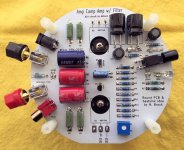
My main amplifier is the 
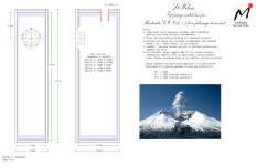
engineer amp from Pete Millet, almost as originally designed, albeit with Toroidy PT and OPTs. The speakers are Elsinore, which I could buy from Helmut, a german "neighboor" who is active on diyaudio.

This setup has been very stable, quick to boot, most of the time stable and reliable. I use Squeeze Ctrl application on my smartphone, or the full GUI of LMS, and seldom the touch screen, as the player is low on a rack, and not really within reach to skip/forward/etc. In my work office, I have an old Squeezebox Touch that feeds a SE amplifier from Elekit and small Magnat desktop speakers.

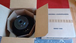
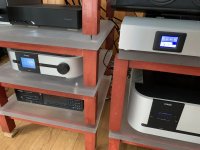
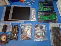
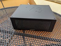
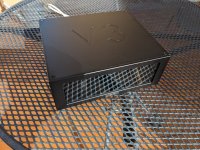
Someone visiting me once said, "it looks all very nice, but this cheap plastic player doesn't belong within sight". So when Vincent started to propose his "Stealth" player on diyaudio vendors bazaar, I was tempted. So I contacted Vincent and ordered a V3 player. I paid the full price and this is my honest review. Vincent has always be very quick to answer, before and after delivery. The delivery took about 2 weeks, Christmas period didn't help. The package arrived in excellent condition. Within the box, everything was very well packed, in separate labeled boxes and bags. The component looked excellent quality, and the metal work is extremely well done. Everything CNC, well adjusted, well-designed with exactly the appropriate tolerances to enable a mount that looks good and doesn't need any filing or fiddling.

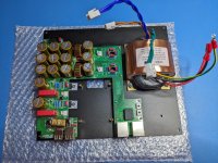
I took my time to build it, not being in a hurry, and wanting to do a good job, eg cleaning the PCBs after soldering, etc. I relied on the BOM and video that made almost everything clear. When it wasn't, Vincent answered my questions quickly.

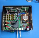
And then came the software part... basically, the setup is a Raspberry 4B, with a HDMI display (Waveshare 7.9). Vincent provides some pre-customized images that can be copied to a micro-SD card. There are Dietpi with LMS, Moode, Volumio. My own goal was to use piCorePlayer again, as I like the extremely fast boot and run-from-RAM, which allows for a power-off with any prior shutdown, without risking to corrupt the filesystem on the SD card.

The quirks are in the way the Waveshare 7.9 display must be configured. It's easy (some edit of config.txt) to get the OS console to show up. However and despite my efforts, I could not get Jivelite to work. I asked its author, I asked the communities, I read many pages, and found out, some other people had the same exact issue. Basically, and until today, Jivelite does not work on this HDMI display. It's a shame, as it uses the framebuffer directly, not X, and is light and fast, without any mouse or other artifacts.

So on to test other distributions. I looked at Dietpi+LMS, but no, I already have LMS. I need a player, not a server. Then Volumio, which I didn't really liked (personal taste, it's certainly a good piece of software). I then tried Moode which worked almost out of the box, has a nice community and support forum, and seems to be just about what I need. I can't do any A/B test, as I plan to continue using my Teac USB DAC, I do not expect the sound to change much, but I haven't got golden ears either. I now run a pre-version of Moode 9, which required very few changes to work with the Waveshare 7.9 display. The whole setup sounds and looks good, no complain anymore, a friend even asked if I would build a Stealth for him 🙂

So basically this is a great hardware offering for those who want a good-looking Pi and screen but do not want to be locked in proprietary hardware and firmware world. The kit is probably not for beginners in diy electronics, but for anyone having build electronics before, it's perfectly doable, thanks to the great attention to details by the designer Vincent.

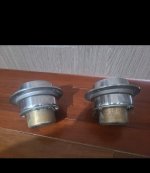
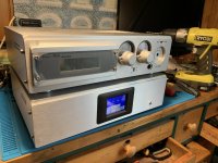
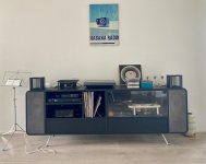
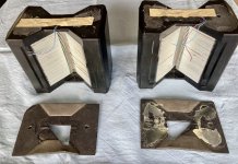
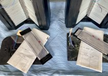
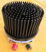
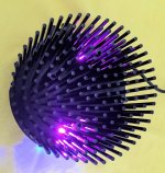
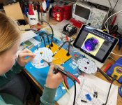
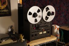
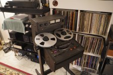
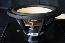
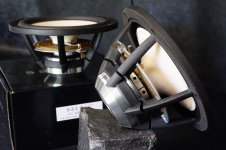
Below some pictures.

Attachments

  • 01_kit.jpg
    01_kit.jpg
    345.8 KB · Views: 173
  • 03_board.jpg
    03_board.jpg
    392.7 KB · Views: 165
  • 04_encased.jpg
    04_encased.jpg
    396 KB · Views: 174
  • 10_closed.jpg
    10_closed.jpg
    310.3 KB · Views: 163
  • 11_closed.jpg
    11_closed.jpg
    387.1 KB · Views: 166
  • 12_allwithdac.jpg
    12_allwithdac.jpg
    217.8 KB · Views: 181
  • Like
Reactions: everylittleyam

Audio transformer for small tube projects?

Hello everyone
Conrad has a small audio transformer that, according to reviews from various buyers,
it can be used as an audio transformer for small tube projects.
I'm just wondering how best to connect it to an EL84SE amplifier!?

https://www.conrad.com/en/p/elma-tt...-1-25-2-5-5-0-10-v-content-1-pc-s-516104.html

the photo on the conrad site gives you eye cancer :headbash:

ELMA_UE1.jpg

Attachments

  • Like
Reactions: JMFahey

Combined Enclosure Calculator (Sealed, Ported, Onken)

Hi all,
Since MH-Audio is not available I reverted back to a number of spreadsheets I've used, and combined, in the past. I posted it elsewhere in DIYAudio, and it worked. That said, please keep in mind, different versions of Excel and other spreadsheet software interact differently with every spreadsheet you throw at them.

The sheet is protected against user error, without a password. So feel free to mess around with it. It'll calculate Onken, Sealed, Ported and give you the ability to change volumes. I think (hope) it's intuitive...

Anyway, here it is, with gratitude to Pano for finding a rebellious link.
All the best,
Ron

Attachments

Can you polish a Solid State T%rd? It seems you can

First, English is not my first Language.

I have an old Fender Solid State Guitar amplifier combo that is mostly used as a 1x10 Cab for a small a DIY Tube amp head with a Ragin Cajun in it. The ubiquitous Frontman 25R. After seeing the Video of Jim Lill "Where Does The Tone Come From In A Guitar Amplifier?" ( Login to view embedded media ) I was thinking if I could make this SS amp usable or at least not terrible, I know that there are fans of this amps but a good tone is hard to dial, the tone is too mid scooped no wonder people play this amp with mids on 10. The clean Vol control goes from no sound at all to too much Vol between the 1 and 2 range of the Vol control. The Dirt channel is bad, really bad. Although some people like it as is. The OG speaker is meh, the easiest mod you can do is to use a better speaker, I put a ragin cajun in it. After studying the schematic I came to the conclusion that Fender made this amp to sound bad on purpose!

First let's tackle the Clean CH
This Clean Gain stage is not clean clean, it increase the high top end frequencies in the lower Vol setting, and become flatter as you increase the Vol.
The Vol control range problems can be alleviated increasing R12, I used a 18k.
1699059997895.png


Now lets' see the Dirt CH. First we encounter a mid focused passive tone shaping. I think this is used to bring brack some of the mids that are cut in the tone stack. I practically removed the mid bump, we will fix the mid scoop later in the circuit. I entirely removed C8, C9 and C10. leaving just a voltage divider with the (22k+22k) and 8.2k.
1699060269155.png


The next stage amplify just bass and mids, I want the opposite, I reduced C12 to 0.047uf to cut more bass (less fart tone) and reduce C11 to 100pf to clip more highs.

1699060574992.png


The next stage is a clipping stage, I did not understand what fender was trying to accomplish here but I changed the stage to be more like a regular soft clipping. I removed D3, D4 and shorted R23. To help reduce some of the ice pick highs I put a 100pf in parallel with R22 (470k). I needed to increase C49 and C50, I put 1uf in parallel in both. to bring back some of the bass cut in the last stage.

1699060708719.png


Both CH are then mixed in U3-A to the shared tone stack. which is the biggest problems of this amp. The tonestack is two circuits in series first a mid control which goes from a fairly scooped mids to a highly scooped mid tone too much to the point of being useless. I think that they were going for a super fendery tone. The second circuit is a two tone Bass and treble circuit . The bass is barely moving the frequency and treble control goes too high compared to the bass control. You end with no mids, few bass and too much treble. No wonder the recommended setting is mids on 10, Treble on 1 and bass on 3. That will give a usable fendery tone resembling the knowbs at 5,5,5 in a classic fender. not good. I just simply removed all of that, I put a point to point classic fender tonestack in there.

1699061436447.png


To fix the problem in the reverb, first the mix control goes from no reverb to a surf rock reverb between 1 and 3 of the control. I put a 47k resistor between the wiper and ground to simulate somewhat a logarithmic response to give more control to the mix control . I then put a B1k Potentiometer in parallel with R44 to add a Dwell control.

1699061596181.png


Lastly I decrease C24 to 100pf to let pass more highs and increased C23 to 1uf to let more bass pass. With the new tone stack those OG tone compensations are not need it. I also inserted an FX loop before R37.

1699061723713.png


All the mods make the Amp usable, more fender style, the tone is more responsive, the range of the controls are more usable and the distortion sound is more tight and focused. usable for a low overdrive or for a high overdrive for hard rock, do not expect a metal tone.

of course this will not replace my tube amp but it will sound good. I you study the schematic of the Frontman 65R and above you will see that they used the classic fender tonestack in those amps for the clean CH, so I was not so crazy. They know what sound good.

Here are the compendium of all the mods with notes, sorry for the crude use of MS Paint.

1699062000118.png


Enjoy!

Attachments

  • 1699060690648.png
    1699060690648.png
    5.8 KB · Views: 162
  • 1699061589914.png
    1699061589914.png
    14.2 KB · Views: 193
  • Like
Reactions: stv

For Sale A pair of Mundorf Supreme Silver Gold Oil 10uf 600vac 1000vdc

A pair of classic Mundorf Supreme Silver Gold Oil Classic 10uf 600vac 1000vdc capacitors available. These have the biggest soundstage depth in the upper regions and do provide a very powerful lower end extension, too. In these areas they beat easily my Duelund Cast and Jupiter Silver Foil caps.

https://www.humblehomemadehifi.com/Cap.html

330€ a pair. Capacitors in Finland, but may ship worldwide. 😎

65dB versus 70dB

I have two different speaker systems that have identical frequency response. They're both three-way.

System A, the "woofer" and "tweeter" meet each other at 64dB, while system B, they meet at 70dB. As stated earlier, two systems are tuned to have their frequency responses identical (or very close) to each other.

Will it have any sound difference between the two? Which one is better?

Attachments

  • A.png
    A.png
    38.8 KB · Views: 96
  • B.png
    B.png
    38.7 KB · Views: 89

Marantz PM-68 Keeps Frying Output Transistors on Right Channel

Hello everyone! I have a serious issue with my Marantz PM-68.

A friend gave it to me with severe distortion on both channels. Turned out it only had bad solder joints on the driver transistors.

I repaired the bad joints and it was working perfectly for about a week...


After that it fried the output transistors on the right channel including :

  • One of the transistors : bf422 (7272 on the schematic)
  • 2 x 47ohm resistors (3322, 3324 on the schematic)
  • The 150ohm Resistor (3326 on schematic)
  • All the Resistors on the bases of the output transistors (4 x 10ohms) // 3328, 3330, 3332, 3334 on the schematic
  • One of the output brick resistor with 3 legs : 3w (2x 18ohms)

After i replaced all of that for the first time it fried the same components again after 2 minutes. Even though the voltages at the bases of each transistor where measuring fine:

PM68-Right Channel.jpg


  • i had my +- 56v from my power supply and and all the transistors where receiving the appropriate voltages.
  • I had my +- 1.6volts at the biasing circuit (transistor 2sc3419 // 7268 on the schematic) and at the 2x 100ohm resistors (3314, 3316 on the schematic).
  • I had my +- 1v at the emitters of bf422, bf423

and so on..

Long story short all the voltages at the bases and emitters of the transistors up to the final transistors where measuring fine and suddenly the magic smoke appeared...

So i replaced all the transistors (look at the attached photo // schematic), electrolytics, diodes (including the zeners) and it worked fine for about 2 minutes again and then poof!! It fried the same components.

The third time i replaced the output transistors i left their bases "in the air" / not connected and was measuring again and again the voltages in the entire circuit even after it was working for 30+ minutes, once i connected the bases it blew after 2 minutes again.

For some reason the output transistors short on all 3 legs taking with them all the components driving them..

A few final notes:


- The left channel is stable and working fine so i don't think it's a power supply issue.
- I was measuring 0mv bias on the channel that's fried even though the voltages where present where they should be, the trimmer was replaced and checked but no matter how i was setting it no change occured.
  • The output transistors where all pretty cool when it happened every time, the driver transistors where hot to the touch but so where the other driver transistors on the left (working side)
  • The Dc Offset at the output for the 2 minutes that it was on without load // speakers connected was about 10mv, i could not get it to go lower than that after i replaced all the transistors. Also in order to get the Dc offset to get to the appropriate point i had to turn the dc offset trimmer about 90% of the way to the max, while before the first failure occured it was at about 50% of the way
  • The third time it fried the outputs it blew the main 15A power supply fuse while before it did not get to that point.
  • The transistor differential pair on the left side measures fine and provides the +-53volts i pulled them and checked them


So this has become a very expensive repair for me since i'm at it for about two weeks now and the same fault keeps occuring.. (3 times so far!!)

Based on the schematic can you think of something i did not?
How could the voltages be correct at every stage but still it blows up?
Is it oscillating for some unknown reason?
Could the transistors i'm buying be fake and causing the fault?


I'm really dissapointed and i ran out of ideas..

Yet another efficient bookshelf speakers build!

Hello, it been some time I haven't build new speakers besides some amplifiers modifications and maintenance, but this time I've build new 6.5" bookshelf speakers, the original project thread started here.

This bookshelf speakers are primarily intended to be driven from a small amplifier/AV(passive) and for when I'm in the mod of listening at low/lean volume levels but not limited to.:cheerful:

The vented box consist of ~15mm(5/8") MDF construction with double(~30mm) baffle sandwich and minimal bracing to conserve some internal air volume space, the outer dimensions are as follow:
8.62"(219mm)Wide x 13.62"(346mm)Height x 12.12"(308mm)Deep, with about ~0.570 cuft gross, used WinISD for the box simulation.

Since this is the first time I've built a pair of bookshelf speakers for efficiency dynamics and clarity, I made few errors while building the boxes but already corrected, also after playing around with drivers options and crossover(active and passive) setups, the drivers of choice were the FaitalPro HF10AK with STH100 for the tweeters and the PRV 6MB550FT midbass.

Also while I'm a diehard Active Crossover All The Way:yell:
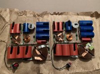
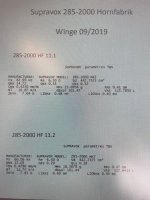
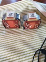
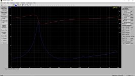
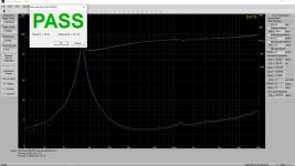
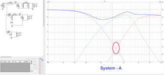
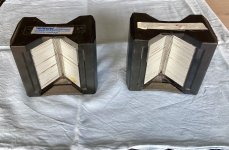
, this time opted for a simple/minimalist 12dB crossover in regards the initial speaker intended use, also the crossover was tuned slightly V-shape on purpose/personal taste with few dB's recessed mids, and of course the passive crossover build was hugely simplified thanks to
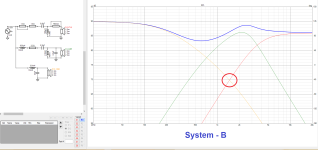
 XSim, VituixCAD and REW software so kudos to their developers.

I've started testing/listening the bookshelf speakers with the 12dB active(DriveRack PA2) and the passive(Current) crossover for comparison/measurements and frankly the difference were so negligible that they will remains passive, though that's what they were intended for, so I've connected them to a small 20WPC chip amp(Symetrix 420) and the little speakers almost drives me out the room, then I've pushed them a bit with my modified Samson S500(with 40Hz/LR4 highpass xover) and the little speakers does scream with huge dynamics without distortion that they really made me smiley though this are just pure speculations.

PS I will split the post in few sections to avoid an initial big post.

Here are the bookshelf boxes build images:
IMG_2659_Small.jpgIMG_2663_Small.jpgIMG_2668_Ed_Small.jpgIMG_2672_Ed_Small.jpgIMG_2695.JPGIMG_2700.JPGIMG_2709_Small.jpgIMG_2710_Small.jpgIMG_2712_Ed_Small.jpgIMG_2800_Small.jpgIMG_2806_Small.jpgIMG_2826_Small.jpgIMG_2835_Ed_Small.jpgIMG_2837_Ed_Small.jpgIMG_2843_Small.jpgIMG_2848_Ed_Small.jpgIMG_2849_Ed_Small.jpgIMG_2855_Ed_Small.jpg

Vitavox Thunderbolt, about to build a test box

Hi All,

For a bit of background info I used to run a pair of Labhorns in my lounge, until I started building horn mains and needed the space for them.
To my ears they gave the best quality bass I have ever heard in my room. I used them for a while for home theatre with 3x sealed 15" tempest subs running 15Hz-30Hz. Worked well. (the tempests never really sounded great to me above 40Hz)
Since removing the labhorns I've been using the lab12 drivers in multiple boxes as subs.
I recently went back to my 80Hz midbass horns (similar to Edgarhorns) with my 2 way MEH horns above, and whilst setting up the horns decided to try and EQ the Midbass horns flat to 35Hz. (These are for normal hifi / home listening levels, not home theater)
To my amazement they took the EQ and did not sound distorted at the loudest levels I listen to my music at.

I'm hopefully going to have a dedicated theatre room soon, and would like to get back to having horn loaded subs. My Labhorns were horn loaded to 32Hz, and I would go back to them except I would have to A: build 4 new boxes and B: buy 4x lab12 driver (approx £850)


Thinking that 4x labhorns would in reality be way too much output for what I will need, and not having a spare grand to spend on drivers I started looking for alternatives.
I went back to the Thunderbolt cab that Freddi had recommended to me a long time ago. This models well with the EVM15L drivers that I already use in my midbass horns (and will be spare once I build my next MEH project) and 4x cabs will allow a multiple sub setup to even out the bass. They have enough excursion to get down to 30Hz at home theatre levels, and I will run my 4x lab12 drivers in a big 4th order BP to cover 15 - 30Hz to fill out the bottom octave.

There's not a lot of info on the web about the Thunderbolts, except 1 drawing that is meant to be very accurate, some dimensions posted by TB46 (1220mm x 810mm x 640mm) back in 2011. There's also a Hornresp model by jbell on some old threads here.

Rob.

Bluesound Node2 PSU repair

My bluesound Node2 is dead with a steady red light on the LED.
Internet search identifies this as eithers a failed software update or a dead PSU.
Inspection shows the usual suspects C11/C12 bulging. The originals are 1.000uF/10 volt.
Unfortunately I don't have any of them, but I do have Long-life, 105º, 1.000uF/6,3 volt.
Does anyone know the actual voltage across these capacitors and if I can get away with 6.3V?

Picture beolow is from internet, but show the same damage on the aptly named capacitors squeezed between the heatsink and SMPS transformer
1702311101211.png

KEF Blade 2 meta vs Reference 5 meta?…..which is better?

I get whole point source coherence thing with the side firing woofers but with an Xo point of 440hz for the Blade 2, my brain can’t process the off axis imaging discontinuance where as the Ref 5 with all drivers fwd firing makes much more sense.

I ask the question as I have a pair of white Q150’s with scratched up cabinets I bought open box a few years ago on impulse for $250 that I had intended to just paint…….but now I’m thinking to harvest the Uni Q drivers instead and build my own active WWCWW. Thoughts?

Pink noise generator

The attached schematic for a pink noise generator of which various versions can be found on the net, seemed easy to build. I have build a kit version with pcb. However, it appears to have an issue. Upon start all works fine, but within no time something makes it oscillate far more than intended. What a pun. The issue takes the regulator (78L08) and IC1 resp. IC2 (CD4066BE) down. The N1-4 IC (CD4093BE) has survived several times. A lab supply of 12Vdc was used to power the unit.

Before re-placing the regulator and IC1, IC2 for a second try, a decoupling cap of 100nF was added at the supply pin of each IC. Alas, the second time went the same dead end. A search revealed this is not the first time with this schematic, but no remedy could be found, apart from the decoupling.

Any suggestion on what is going on and how to cope with it?

Edit: the IC1, IC2 are CD4006BE (not 4066), but as per post 4 this should not matter.

Attachments

  • Pink noise generator.png
    Pink noise generator.png
    48.9 KB · Views: 338

Line stage using 6V6, 6W6, 6G6, 6F6 etc. in triode?

There are many happy builders of 6V6 line stages thanks to the long thread on this. But what of all the other similar pentodes/tetrodes that can be used in triode?

What have been your experiences with these, and which were you most pleased with?

6V6 - 6.3V/
6W6 - 6.3V/1.2A
6Y6 - 6.3V/1.25A
6F6 - 6.3V/700mA
6G6 - 6.3V/150mA
6K6 - 6.3V/400mA

Other......

Plan request: A Traped horn to go from 35(ish)-120 w/RCF L18P200

Hey Guys

I have 2 of the RCF L18P200-N drives laying around and i would like to build a traped horn to put them in, if its posible to get one cap to go from 35hz(ish) to 120hz and around a 100-101db spl minimum in the bandpas it would be soooo sweed!

They have good power handling (800w AES) and a large xmax (9,8mm) and i can get 2 more pretty cheap 🙂

Is this posible ? is there a designe that will do this or am i looking at making a new designe?

Cheers Toby


(sorry for my bad english)
Same post on speakerplans.com...

How accurate is WinISD?

Hi all. First let me say i have never built a speaker, and this is the first time I have used winisd. I would like to build a sealed box speaker using the new SBA 8" fr driver. Downloaded winisd and came up with a 46.55 liter box. Then I went to an online modeling site and they came up with 45 liters. So far, pretty close. However, the Madisound site that sells the drivers recommends .6 to 1.0 cubic foot box. or roughly 16 to 28 liters. I have also read where stuffing the box with polyfill or whatever makes the box effectively 20 to 25% larger. So now the driver thinks its in 54 liter box???? I don't quite know what to believe here.

Never used winisd before so it is entirely possible i did something wrong, but on the other hand, the online calculator agreed pretty much on the size of the box. I understand the compromises of a sealed box vs vented but am willing to sacrifice some bass for better accuracy. I also want one the correct volume so it doesn't lose the effect of the sealed box properties.

So, did I do something wrong or is the seller wrong??? This will be a first time build, and have wanted to try an FR driver for some time now. Just want to get it as correct as possible to get the best results I can. Any input is greatly appreciated. Thanks, J.D.

Driving the Beveridge ESL

I was just looking at the direct drive amp for the Beveridge HB2 and noticed something peculiar.
Normally, in an ESL the diaphragm is biased to a high DC voltage, and the two stators are driven in opposite phase.
Looking at the Beveridge circuit, it seems different here.
It appears that the diaphragm is DC grounded and AC driven from one phase, while both stators are at opposite DC voltages (+/-3200V) but AC driven with the same signal, in opposite phase to the diaphragm.
What do you think?

Jan

Attachments

  • ESL-beveridge-2sw.jpg
    ESL-beveridge-2sw.jpg
    261.3 KB · Views: 585

Ibanez guitar amp plays for a minute then stop

Hi, got an Ibanez tone blaster tb15 with the following issue:
When powered on, it works as expected for about a minute or just a little more. Then the amplifying level is dropping in a few second to total quiet.
Now if I'll power it off an on again, it'll sound strong hum sound for less then a second then quiet, and repeat that continuously.

Powering it off for a few minutes, and I'm back to the beginning where it plays for about a moment.
Thought it's the main capacitors, one of them had an issue so replaced both.

Any idea how to fix it?

Thanks !

For Sale Viborg pure copper XLR Chassis mount connectors

I bought a whole bunch of these but have decided not to use them. I don't have the energy to sell them in pairs, I'd love to find a DIY'er or amp builder who wants to buy all of them at a great price

I have both Gold and Rhodium plated. These are 3 pin Chassis mount XLR pure copper connectors.

I have the following:

20 Rhodium Male
16 Gold male
2 Gold Female

They are all unused in the original box except one of the Rhodium male connectors is in a zip bag with no box.
They sell new for $15 (Gold plated) - $17 (Rhodium plated) each on Aliexpress, the lot is worth $610 new.

how about $200 shipped in the USA for all of them? Or anywhere if you pay shipping. That's 70% off the new price

Pictures on Imgur here


Cheers everyone!

On Wall Speaker Design and Build - Input Appreciated!

Hello,

I have built several speakers from kits and proven designs and I would like to design and build something more specific. I have been using commercial on wall speakers in my living room for a couple years and they can provide a better sounding and balanced lower end when speakers cannot be placed 2-3ft out from the wall. BUT, there are also potential issues at both ends of the frequency response.

The bass response should account for boundary reinforcement, and the treble response can be limited by placement. Wall mounted speakers cannot be toed in and out to balance the treble and the location of the speakers on the wall may be limited by the location of wall studs, fire places, TVs, shelving, etc. Placement near-wall on stands might be a solution for some, but for true on-wall speakers these limitations require some combination of the following “solutions” to get the treble “right” (whatever that means to you).
  • An angled front baffle
  • Wide, controlled dispersion
  • Bright on-axis frequency response such that the off-axis is more ideal
While applying any one of these might work, I believe that a conservative combination of all three will provide the most flexibility in both design and speaker placement. Does this make sense to you all?

Goals:
  • 2-way constant(ish) directivity (without a custom waveguide)
  • <12L sealed
  • Frequency response to account for boundary reinforcement at low end and slightly bright to balance off axis listening
  • I will be using with a sub
  • Max SPL> 99 db @ 1m. I listen at around 77 db @ 3m from each speaker equating to 84 db(per speaker) @ 1m, but I would like at least 15 db headroom, hence 99 db.
  • Tweeter below the woofer. This is the only way to get the tweeter at ear level in my room.
  • Distortion less than -45 dbr above ~100 Hz, 84 db @ 1m. This is the measured room noise floor relative to the preferred volume at listening position. This is more aspirational.

Maybe something that will look like these R speaker concepts:
1710437110813.png

1710437139340.png

Room integration concept of the “sweet spot” for mid and high FR:
1710437182492.png


I will be comparing the final product to my Dali Ikon On-Wall and Revel s16 speakers. My goals are largely the best of both worlds from these speakers. Both are good, but have issues which I hope to solve in this DIY.

Drivers:
Woofer - I would like to use a pair of ScanSpeak Illuminator 18WU/8741T which I got used. WinISD suggests they should be fine in a 12L sealed box which gives a Qtc of 0.79. Have I interpreted this correctly? Are there other considerations at this point?

Tweeter - The SEAS Prestige 27TBCD/GB-DXT (H1499) tweeter appears to fit the prompt. The trade offs are $ and sensitivity. I have plenty of power available and this tweeter appears to have well controlled directivity and reasonable dispersion without the need for custom waveguides. Other suggestions are welcome.

I will measure the drivers in the enclosure for the final crossover design, but as a proof of concept and a learning exercise, I’ve modeled a crossover in VituixCAD for these drivers which I think will provide the in room balance I’m looking for. I’ve also included the modeled effect of the baffle and enclosure. Just hoping to make sure these drivers are compatible before I start laying down money and making saw dust. I have spent about an hour reading about crossover design, so I have a lot to learn and more reading to do.
1710437248293.png


Any input is appreciated.

Thanks,
Joseph

UKC av326BT - burned

Hello guys. I am prety new into this. I bought this cheap thing UKC AV326, but seems like I've short circuit the left channel, and the smoke machine was triggered inside.
I've opened it, and noticed one resistor 39 Ohms was burnt. Replaced it, but it burned again. No sound during burn tho.
Any idea where to start with this thing to repair it ?

Attachments

  • 440884722_10228784124901062_6820398814550171377_n.png
    440884722_10228784124901062_6820398814550171377_n.png
    5.4 MB · Views: 91

Has anybody built a FSP 18 SXY?

Ive been looking for the best possible subs i can build for my dub, tekno and psytrance system.
I love folded horns/ front loaded horns because of there size, shape and output.
But i don't know what the best option is.
I will use 2x 1850 horns as kicks.

The Fsp-18-sxy peaked my interest, it looks very nice and the response and plans look good to.
But i dont think anybody has actually built them, at least i can't find any.
The buildplan is easily findable on the interenet and you can also see it here :
https://planssystemes.notion.site/F...e606ccad58?v=a0a05a48606240f3b820a0984fabfc39

Does anybody have more info on this horn? should i build it? Should i first test a single one? Should i design my own flh?
Any other recommendations?

Thanks in advance!
Cesar Baets

Luxman MB3045 biasing guide/help

Hello all and thanks in advance

I recently purchased a beautiful pair of Luxman MB3045 amps. They are running well but given the age and the previous history being unknown I would like to check the bias etc on them.

I have done a bit of a search online and thought I would come across a service manual, guide or similar on how to perform it but no such luck.

If anybody has the info or can put me in the right direction it would be greatly appreciated. I am a qualified electrician and have worked on voltages up to 330kv and have a healthy fear so I am aware of the danger.

Thanks
439728254_770254151751033_6778552697983472003_n.jpg

Tone and Loudness Controls

In the December 2023 of AudioXPress Doug Self has a great article on tone controls. The controls that he describes are peaking controls rather than shelving controls like what he described in Jan Didden's Linear Audio #5. The new tone controls are much simpler in design than those in LA #5 and they sound great! Soon after buying the December issue of AudioXPress I read Doug's article and built the described pair of tone controls. I then wired them in place of the LA #5 controls that are part of this Doug Self Preamplifier and I really liked them! I found them to be a bit more musical and easier to tune than the LA #5 tone control. More than anything I suspect that what I am hearing is my personal preference for peaking rather than shelving filters. Peaking type filters are common in studio recording consoles and pro gear.

The intent of this thread is to not only explore the need and implementation of tone controls but loudness controls as well. What is the best way implement a loudness control? I personally think that one that tracks with the volume control would be a good idea. Less than that I would settle for one that changes EQ dependent upon turning a 'loudness pot' much like a volume control. Doug offers up a good tutorial on loudness controls in his book 'Small Signal Audio Design', 3rd edition. the Loudness tutorial start at page 373

I want to hear any and all thoughts on the topic as well as posting your favorite circuit for doing tone controls and/ or loudness. Let's make this a monster thread demonstrating many ideas while respecting one another's opinions. I've asked Doug to join us as well.

Full range diy vs brand multi way speaker

Hello everyone. I was crazy about building some full range speakers with Markaudio drivers, after having seen their constructions on YouTube.
The idea is to use the CHR-120 or the CHN-110, in large boxes such as the St Helens for the latter (Fb 32hz, upward firing, 30.6 liters). Or the Classic 35 liters vented box for the CHR-120 (Fb 36 hz)
I would lean towards CHN-110 in St Helens as the driver is cheaper.
I currently have some B&W DM602 S1 amplified with Marantz PM6006.
How would the B&W DM602 compare to the CHN-110 built speaker in the St Helens box?
Greetings and thanks.

Attachments

  • CHN110-St-Helens-top-firing-vented-box-1038x673.png
    CHN110-St-Helens-top-firing-vented-box-1038x673.png
    79.8 KB · Views: 129

Finaly finished Ian Canada base DDC project

Here are some pictures of my finished project. I have build my DDC so I can feed my May KTE true I2S. It’s build around a a Raspberry Pi4 and I use Ian Canada component. From the tranfo, I go to a ultra low noise linear PSU (LinearPi) and go in DC to the PurePi that give me pure DC. I then feed the StudioPi Pro. On the left side of the StudioPi I have an Amanero Combo384 and the Rasbery Pi 4 and on the right side I have the reclocker FifoPi Q7 and the Hdmi Pi Pro. I also installed the touch scrren to control my input. The case is a Nagra style case, it goes well with the amp I have built from ICE Power module.
333307651_593772748976649_4985803936711466485_n.jpg
333289164_143482361925611_4979779289443397907_n.jpg
333056043_1439069039962885_5496076037480209355_n.jpg
333049240_2146117492444449_8745773961734744442_n.jpg
333031690_904699830675694_6977218964479673251_n.jpg

This DDC can work with my HTPC with ROOn or JRiver or it can work alone and stream from the RaPi and Volumio. I can also external Hdd directly in this DDC. The sound is simply outstanding with the Holo May

Attachments

  • 333027760_746497307150077_7882892333688579838_n.jpg
    333027760_746497307150077_7882892333688579838_n.jpg
    259 KB · Views: 327
  • 333435734_740885037630676_703077864838440311_n.jpg
    333435734_740885037630676_703077864838440311_n.jpg
    221 KB · Views: 379
  • Like
Reactions: userguide

Inductor for low pass

Hi all!
It has 2mH iron coil inductor in the crossover of the bass section for my 3 ways speaker.

Normally, an iron coil used in the crossover of the loudspeaker has ABOVE zero DCR.

If I use the Mundorf Feron Core VN (MCOIL VN · FERON ZERO-OHM RESIN SOAKED) range to substitute the existing iron coil inductor that DCR has more than zero, what would happen for the end result?

https://www.mundorf.com/audio/en/shop/Coils/EI_Coils/MCoil_VN/

Thanks!

DBA 1600.1D has red and green light

Every 5 to 6 amplifiers I get on my bench has something I can't figure out.
I have a dba 1600.1D on my bench.
1. Powers up no shorts, all Power SW50N06, Output 2SC520 and Rectifiers F12020A & F12020C tested good.
2. At idle it consumes .56 amps with no voltage drop.
3. T494 tested good, has +12v on pin 12 and -0v on 7. no pwm on e1 or e2, has .347v on pin 4
4. Op-Amps have nothing. I replaced the PC817 Optocoupler.
5. 12v on both rails.
6. Changed both diodes in5408. changed all transistors down the middle.
7. I get 12v on primary side of the transformer and only 7.4v on secondary side.
8. I tested all resistors and diodes.

20240416_070320.jpg
20240416_070336.jpg
20240416_070329.jpg

Secondary light emanating through the top support in 6HB5?

So these reside in an Acoustat Servo Charge OTL. On standby, the filaments are lit up as normally, slight glow. I'm seeing tiny specs of white light poking through the mica support at the top. They are bright but very tiny. I have 3 other amps just like it in the same system. It's only happening in one. Does anyone know what this is? TIA

Velodyne DD12 DSP chip

Hi people.

Just had a quick question about this DSP chip inside my Velodyne DD12. A good while ago the DSP chip failed and Velodyne have 0 spare chips.

I have tried to source a few but they are more than likely fake as Texas Instruments have not produced this chip for a good few years as they specifically made it for Velodyne.

The sub is in perfect condition and I really do not want to have to sell it as spare parts.

Do any of you recommend anything?

Attachments

  • Screenshot_20240430_113356_eBay.jpg
    Screenshot_20240430_113356_eBay.jpg
    163.8 KB · Views: 67

NAD 720BEE pre-amp analysis

Greetings,

Attached is a schematic that includes the pre-amp modules of the 720BEE (at the bottom).

Does anybody recognize the circuitry used in these in/out modules? Is it a clone of a good pre-amp design or something proprietary by NAD?

Thank you!

Attachments

Re-purposing two half-used 12AX7 to add in a pre-amp on my KT88 Tube amp

Hi there, very green here. But Ill dive right in.

I have a KT88 Tube amp, as seen in the photo below, I bought it second hand. The two smaller tubes in the front (12AX7) from what I understand only have one side of them used (ie one line per tube), though are capable of having two lines running through them. The reason for having a tube per line here is presumably for aesthetics? is this the only reason?

Well, its a little quite. I am wanting to build a pre-amp to bump up the gain before it goes through the current KT88 amp. My main question is, can I simple divert both channels through one of the two 12AX7, and re-purpose the other in this system as preamp tube. Im looking at building something like this which requires one 12AX7 Tube. This would save me having to buy a new power supply, and another tube, and socket and....

Im looking to redo the chassis for the KT88 Tube amp so I could make it a little larger, thought the preamp in the build above doesn't look to have a large footprint.
Are there any issues when integrating a preamp into an existing tube amp?

if this is fine, would it be best to use one for the purpose of pre-amp and the other as the pre-boost (which it currently does), or keep the lines separate so one side of of each 12AX7 is pre-amp, and the other continues to do the boosting that it already currently does before feeding into the KT88 tube?

Hope this make sense!
Thanks in advance.
Luke

IMG_5496 Medium.jpeg

On epoxy potting an EI transformer

G'day Guys.

I am considering potting a pair of power transformers.
They are salvaged from Pioneer multichannel home theatre amps.
20240429_213807.jpg
I have modified the main secondary to split the centre tap into dual secondaries to suit my power supply design.
20240428_212854.jpg
Once I attach some fresh lead wires, I would like to seal everything up nice and tight such that things can't move, short, vibrate, corrode etc.

Now come the questions:
1) If I was to encase the whole transformer in epoxy. Is there an advantage to using a steel box for additional magnetic shielding over say aluminium or plastic?
2) If using a metal box, should the transformer frame be connected to the box for grounding or should it be electrically floating?
3) If the whole transformer is potted, what would be the derating to be applied, 20%?
4) Are there any disadvantages to potting the whole transformer other than power derating and the inability to fix things in case of a fault?
5) Would a good option be to simply masking tape things up and pot only the area where the wires terminate:
Potting.jpg
6) Is epoxy the best option? Would polyurethane resin be more suitable?
7) Am I over thinking this whole thing? Should I simply heatshrink everything up and be done with it?
  • Like
Reactions: TonyTecson

Recapping Philips D6800

Hi everyone!!
I'm about recapping/adjusting an old Philips D6800 portable player.
I have another similar unit (AZ6801) which is different on the outside but identical inside. The AZ6801 is completely disadjusted and I'm waiting to arrive a signal generator to adjust it with my oscilloscope. I will also adjust the D6800. The adjustments will not increase the sound quality.... it's just for adjusting the lens, to avoid reading errors/track jumps, etc...

Both players sound is identical: not bad, but mediums are too high. I don't know if a recap will solve this, or this is just the kind of sound on this units.

I opened both players and they have a lot of caps. Some caps are blue (philips).
The main question is: can I recap it using normal caps?? In my closest store they sell normal "Jackcon" capacitors and other cheap brands. Can I use this kind of capacitors?
Or maybe I should look for better brands on the internet?
Thanks!

The mysteries of the Cairn Boost phono stage and adjustable capacitance

Hello!

Does anyone have a manual for this lovely phono stage?

Everything seems quite straight forward apart from the (DIN?) switches at the bottom which adjusts the capacitance and is a bit confusing to my simple mind.

There are various MM settings suitable for my Goldring E3 cart which has a load capacitance of 100 - 200pf (according to the website). The phono stage offers either 100 or 147pf in that range and then many more both higher or lower.

Which of these settings do you think is better and if I was to go for a higher / lower capacitance on the phone stage, what would the effects (sonically or otherwise)be?

Hope you can help?

circuit strategies of power amplifiers

Hi everyone
I recently read about the old QUADs and the interesting technique adopted by these amplifiers. It is a strategy, other people would use the word trick. It is a low power class A circuit which is used to correct errors in the second power circuit in class A/B.
there is a lot of talk about the class to which the amplifiers belong and the type of sound they produce but too little about the design of the electronic scheme chosen by the designer. I can understand that this topic is not very interesting for many people but it is not essential to go very in depth, it is a brief description of the properties that derive from it is sufficient. Having said this, it would be nice if someone would like to mention other ingenious circuit strategies whose existence I probably don't know.

For Sale Dorati DAC

This is a credit card size DAC with i2s inputs, with discrete IV.
One good sounding little module that amazed me.
I have changed the output cap to a 4.7uf Wima film type, because i am using it to drive preamps.
If you are driving HP, i suggest you change the caps to bipolar electrolytics of value 220uf. The Elna Silmic 220uf/16v will fit here.
I bought this board from a member here who bought the kit and spent time and effort to do a nice and neat soldering work.
Since i am more of an adventure person and this board is not designed for that purpose,
I have decided to sell it. Very helpful creator of this board if you need support.
More info can be found here : https://www.diyaudio.com/community/threads/dorati-nos-dac-kits.387035/

USD60 shipped (registered + tracking)
Paypal FF only please.

For Sale AMT ribbon / pair from 1970‘s

AMT ribbon tweeter / pair (1970‘s)
They are in working order and in the offer included are 2 ribbons, which are replaced in 1980/1981. They are from a friend, who took them from his ESS AMT 1.
I‘ve tested them with a 4mF PIO cap (10 kHz/6 dB), Goodmans 6x9 fullrange, ACA-mini and they sound nice. The replaced ribbons do work too.
Because of the weight ((12 kg+) pick up in Zurich is preferred.
Asking CHF 250.- / open for offers

Attachments

  • IMG_9769.jpeg
    IMG_9769.jpeg
    310.5 KB · Views: 122
  • IMG_9770.jpeg
    IMG_9770.jpeg
    597.4 KB · Views: 130
  • IMG_9772.jpeg
    IMG_9772.jpeg
    735.7 KB · Views: 118
  • IMG_9773.jpeg
    IMG_9773.jpeg
    721.6 KB · Views: 116

Not exactly a Group Buy: bare boards for RACAM (Round ACA Monoblock)

Nelson Brock created a bloody wonderful implementation of the Nelson Pass "Amp Camp Amp" (ACA) and unveiled it a Forum thread: (here)

I liked it so much that I copied & reimplemented it, creating my own PCB layout, including a couple of new features (in post #57 of his thread). I called it "RACAM".

A few days later, Mr. Brock announced that he is working with the diyAudio Store to sell full and complete kits-of-all-parts, including PCB, (in post #70)

I want to support both the Store and Nelson Brock, so I won't publish my Gerbers, because I don't want to accidentally enable unscrupulous copycats and counterfeiters. Nobody wants $2.00 crap on eBay and Ali Express, labeled "guaranteed genuine Nelson Pass Amp Camp Amp". Certainly I don't.

However, for those confident and brave and experienced diyAudio members who (a) desire blank RACAM PCBs; (b) don't want to wait for the Store to begin selling full kits-of-all-parts; (c) are perfectly happy to order all of the necessary parts themselves: maybe I can help you.

I am willing to order a batch of ten PCBs from my Chinese PCB fab of choice [JLCPCB] and instruct the fab to ship those boards to your address. This way there is only one shipping fee (fab to you), whereas a traditional Group Buy would encounter two shipping fees: (fab to me, then me to you). The total delay is smaller too, because there is one fewer stop on the journey. Best of all, for orders outside my country, I don't have to deal with international customs paperwork. The fab handles all of that, and they are very experienced at international deliveries.

And nobody sees or touches the Gerbers except the fab and me.

The cost is approximately USD 40-60 for ten boards, shipped to the United States. The price will be somewhere between USD 60 and USD 80 for ten boards shipped to an address outside the United States. As a naive American, I was quite surprised to discover that the customs fees are VERY different for different countries. Higher in France than in Italy, for example. So I have installed an "approve the price quote" step in the buying procedure to avoid unhappy surprises for the buyer.

If you don't need all ten boards, you can give away your extras for free, or sell them at your cost, or sell them at a profit, to other diyAudio members. In effect you become a local distributor of RACAM boards in your own corner of the world.

Working with diyAudio member @peppennino , I ran a trial of this procedure and it worked handsomely. I ordered the boards in California on 28 Feb, and they were delivered to him in Italy on 11 March. JLCPCB and their shipping partner DHL International Express handled everything.

Here's how it works.
  1. Send me a Private Message "conversation" containing your ship-to address EXACTLY AS JLCPCB WANTS TO SEE IT (attachment #5 below -- boxes with red asterisk * require a nonblank answer). Please answer all nine of their questions.
  2. I will get a price quote from JLCPCB for delivery to your address with your country's customs fees. I will send this price to you by private message and ask for your approval.
  3. You respond with your approval and a promise to pay $X per the quote.
  4. I will send you my PayPal userID.
  5. You send me the specific quoted price, by PayPal, as a birthday gift.
  6. I tell the PCB fab to build ten boards and ship them to your address.
  7. About ten days later, JLCPCB emails me the tracking number of the package, and I copy that to you in a PM.
  8. Boards are delivered to your address.
  9. You decide what to do with the extra boards you don't need.

Notice that you never see the Gerbers, and I never see your banking information except your PayPal ID. Also notice that I never touch your PCBs and I don't go to the Post Office to fill out customs paperwork.

ANSWERS TO FREQUENTLY ASKED QUESTIONS

1. I don't have any knowledge of the status or schedule or quantity or price, of any diyAudio Store products. Not even Nelson Brock's ACA Redux.

2. I only offer bare PCBs. Nothing else. If you prefer a full and complete kit (and who doesn't?), buy from the Store

3. I only offer batches of ten boards. I only offer one price and one shipping option.

4. I will not release the Gerbers

5. Tips for builders are found in (post #77) and a parts list is attached to (post #89)

6. This isn't a dead-simple project suitable for absolute beginners. However, Patrick Farrell's 11 year old daughter did successfully build a pair of these, there are photos in (post #80) . She and her Dad have built other amplifier PCBs before this one.

14 MAY 2022 UPDATE: my fab of choice has raised their shipping and handling fees, so now every RACAM build job I schedule (including to USA) will include an individual price quote and approval, before the PayPal money transfer.


_

Attachments

  • Ckt_Stuffed.jpg
    Ckt_Stuffed.jpg
    213.9 KB · Views: 1,530
  • rear_view.jpg
    rear_view.jpg
    201.9 KB · Views: 1,444
  • Pink_glow.jpg
    Pink_glow.jpg
    212.3 KB · Views: 1,407
  • PF-HedghogACA_07.jpg
    PF-HedghogACA_07.jpg
    495.4 KB · Views: 1,145
  • Address_Format_JLCPCB.png
    Address_Format_JLCPCB.png
    10.7 KB · Views: 804
Projects by fanatics, for fanatics
Get answers and advice for everyone wanting to learn the art of audio.
Join the Community
507,700
Members
7,884,895
Messages

Filter

Forum Statistics

Threads
406,067
Messages
7,884,895
Members
507,700
Latest member
Tomasz 026