Cubo Infra

Also known as Cubo HT is designed for Home Theater and low bass songs (B&B Bass Boosted). It extends into the realm of infrasound, frequencies below 20 Hz that are felt rather than heard, nothing too much just enough to justify its name. Experience (truly) scary low sound effects in movies or voice modulating bass lines in songs. Lots of amplifier headroom is advised but only a few hundred Watts is needed to get you started. Full plans and marketing talk here: freespeakerplans

Cubo Infra is not for the faint of hearted, if this is your first subwoofer you might wanna start with Cubo Home instead. The current plan for Cubo Infra is the 3th prototype, the measurements are from the first, although little has changed. Scroll down for the Imperial version.

The design allows it to be placed with the driver aimed towards its audience (or any other direction), with rubber feet of 2 cm (4/5”) height it can be used in a down-firing position. This maximizes the effective front chamber volume, creating an acoustical low pass filter that makes it sound like it drops lower and it can also mask mechanical driver noises.

The measurements below show the response in a corner*, in down-firing position, with a 24 dB/ octave Linkwitz-Riley low pass at 60 Hz or 80 Hz without a high pass. Based on hearing alone the response drops off quickly below 17 Hz. Of course measurements inside a room are very sensitive to sub placement, listening position and the dimensions of the room.

* One thick stone wall, one thin stone wall and a wooden floor

Front view:
zF10YZu.png


Side view:
wX9x2ah.png


Down-firing:
Ut0Rut9.png


Construction plan:
xZvGnbX.png


Cut Sheet:
YjdPG9u.png


Measurements:
013Y8XE.jpg


Magenta: Microphone in close proximity, 24 dB/ octave low pass filter at 80 Hz
Purple: Microphone in close proximity, 24 dB/ octave low pass filter at 60 Hz
Turquoise: Microphone at 1 meter, 24 dB/ octave low pass filter at 60 Hz

Best regards Johan (a.k.a. Cubo)

Hello forum!

Hi everyone!

I am a hobby guy, who is for ever trying to learn how to build design and build electronic circuits for any kind of different applications. Typically, I will have some idea of something I'd like, and then see if I'm able to actually make it work.

My projects typically revolve around microcontroller projects, I'm a fan of ESP devices (and old ATMEL chips).

Recently, I have also started looking into analog electronics, where I'm trying to build sound/music circuits -- like fuzz for guitar, or echo for vocals (microphone).

For Sale IKALOGIC SCANAQUAD SQ200 Logic analyzer and digital generator 200MHz + TrigBox

ScanaQuad SQ200 (IKALOGIC) 4-channels 200MHz
ScanaQuad (SQ) is a series of high performance 4 channels logic analyzers and digital pattern generators. They are designed to be your best companion when working on serial protocols like UART, SPI, I2C, 1-Wire, USB, I2S, CAN, LIN, RS232, RS485, and more. With ScanaQuad Logic Analyzers, you can capture signals, you can play them back, and you can even build genuine test signals and generate them!
Being able to capture and generate logic patterns simultaneously with the same tool, is extremely useful when debugging Logic signals, and it only comes with ScanaQuad.


LEGAL Information

Complies with the following applicable European Directives: Electromagnetic Compatibility (EMC) Directive 2004/108/EC, Low-Voltage Directive 2006/95/EC, IEC61326-2.
RoHS Compliant 2011/65/EC. This device does not contain any of the substances in excess of the maximum concentration values (“MCVs”) defined in the EU RoHS Directive.
Complies with part 15 of the FCC Rules. Operation is subject to the following two conditions: (1) This device may not cause harmful interference, and (2) this device must accept any interference received, including interference that may cause undesired operation.

CAN ICES-3 (B) / NMB-3 (B)

ScanaQuad (SQ) is a series of high performance 4 channels logic analyzers and digital pattern generators. They are designed to be your best companion when working on serial protocols like UART, SPI, I2C, 1-Wire, USB, I2S, CAN, LIN, RS232, RS485, and more. With ScanaQuad Logic Analyzers, you can capture signals, you can play them back, and you can even build genuine test signals and generate them!

Being able to capture and generate logic patterns simultaneously with the same tool, is extremely useful when debugging Logic signals, and it only comes with ScanaQuad.

All ScanaQuad devices have 4 channels. They can Capture digital signals, Generate digital patterns, or do both simultaneously.


ModelSQ25SQ200
Sampling Frequency (Max.)25MHz200MHz
Embedded memory1MB16MB
Digital pattern generatorYESYES
Mixed modeYESYES
Input protection± 12V± 35V
Trigger optionsEdge - Level - PulseEdge - Level - Pulse - serial protocol
Adjustable in/out voltageNOYES
Adjustable input impedanceNOYES
Open drain output optionNOYES
Differential input pairsNO2

overview_sq_2compressor.png


UNIQUE FEATURES, UNIQUE PRICE TAG


MIXED MODE OPERATION

mixedmodecompressor.png


The ability to capture and generate signals simultaneously open a whole new set of perspectives when it comes to debugging your electronic project.

DECODE AND ANALYZE

mos_analyze.png


Analyze protocols with software tools that gives you a global views of your data and helps you to identify bugs quickly.


ADVANCED TRIGGER

triggercompressor.png


Enjoy a versatile trigger system that can target a specific UART byte, I2C address or any other sophisticated data pattern.


TRIGGER OUT capability to their logic analyzers!

As the name implies, it adds Trigger IN/OUT capability to the existing range of ScanaQuad logic analyzers. The way it works is quite simple: A special synchronization signal is exposed to the 5th pin of the USB connector, and a custom (5 wires) USB cable is used to get that sync signal to TrigBox. Adequate circuitry then provides deterministic propagation delays as well as 50 Ohm drive capability on the Trigger OUT line.

tb5.jpg


TrigBox allows ScanaQuad to sync with any existing instrument. For instance, you can use the ScanaQuad to trigger an oscilloscope on a specific protocol feature. Alternatively, you can use trigger IN feature of TrigBox to let ScanaQuad start capturing signals according to another instrument in your lab.

Attachments

  • ikalogic-2.jpg
    ikalogic-2.jpg
    179.1 KB · Views: 31
  • IkaLogic-TrigBox_1_1600x900.jpg
    IkaLogic-TrigBox_1_1600x900.jpg
    100.5 KB · Views: 26
  • IkaLogic-TrigBox_4_600x.jpg
    IkaLogic-TrigBox_4_600x.jpg
    40.2 KB · Views: 24
  • maxresdefaul1t.jpg
    maxresdefaul1t.jpg
    87.7 KB · Views: 27
  • maxresdefault.jpg
    maxresdefault.jpg
    100.4 KB · Views: 28
  • sq200 logic analyzer overview.jpg
    sq200 logic analyzer overview.jpg
    160.2 KB · Views: 25
  • v_sq200compressor-1000x1000.jpg
    v_sq200compressor-1000x1000.jpg
    88.1 KB · Views: 30

PCB: low voltage On-Off switch drives AC mains relay \ includes soft start .. H9KPXG

I got fed up with DIY power amps whose AC mains On-Off switch is on the rear panel. This choice does reduce the amount of metal working required; just buy an all-in-one plastic molded unit containing IEC inlet jack, fuse holder, and AC mains rated switch. Cut one rectangular hole in the rear panel (where small mistakes in drilling or filing are not visible!), drop in the unit, done! But reaching through the equipment rack to operate a switch on the back panel is clumsy to watch, and awkward to do. I wanted something a little more refined.

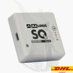
Front panel switches with a circular pushbutton and colored illumination looked promising; the type called "Anti-Vandal" appealed to me. Figure 1 shows a few examples of them. UNFORTUNATELY, most of these switches are rated for low current DC applications like soda vending machines; very few are rated for AC mains switching at the high currents needed by power amplifiers. Worse yet, the 
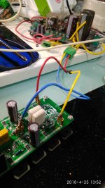
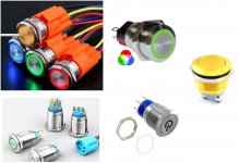
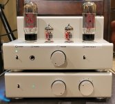
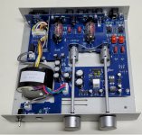
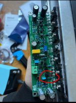
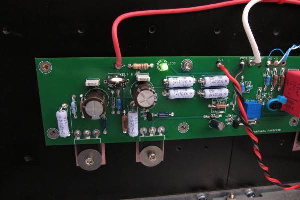
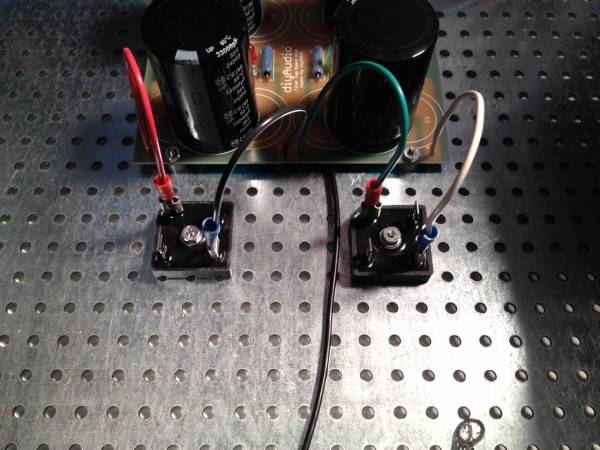
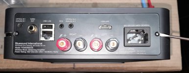
inrush current that flows through the On-Off switch at the instant when the gear is turned on, can be enormous. Far too high for a switch rated 2A @ 24VDC. Figure 2 shows the measured AC mains current which flows, when a rather modest chipamp-based power amp 
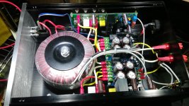
(photo) is turned on. The inrush current peak is 24 amperes: (2.4 vertical div X 10 Amps per div). That's quite a stress for everything in the AC mains current path, including the On-Off switch's contacts. And remember, this is not some super-amp behemoth from Krell; it's just an Antek 200VA toroid, two LM3886 amp channel boards, and a diyAudio Universal Power Supply PCB. Yet its inrush current is frighteningly large.

It seemed to me the only way to use the Anti-Vandal On-Off switches I liked, was to use them at low current & low voltage. They wouldn't directly switch the mains; instead they would merely control a separate big, robust, high-current and high-AC-voltage switch. Perhaps such as a mains rated relay or triac.

Regrettably, more than half of these Anti-Vandal switches are momentary pushbuttons; they don't have latch-in-position action like rocker switches or toggle switches. To use them on the front panel of a power amp, an electronic latch or flipflop would be needed, giving "push on, push off" behavior.


SMALL LIGHTWEIGHT FRONT PANEL SWITCHES

Nelson Pass's 1992 amplifier DIY project called A75 (class-A, 75W/ch) used a triac to switch the AC mains off and on. The triac was controlled by a small front panel switch. The circuit reduced switch current to single digit milliamps, but it did require a front panel switch that can withstand the full AC mains voltage (230V in many countries). Very few of the Anti-Vandal switches meet this requirement, unfortunately.

Canadian high-end power amp manufacturer Bryston used an always-on, micropower, low voltage DC supply for their front panel power switch. It fires a triac, and the triac switches the AC mains on and off.

Australian engineer and prolific DIY project creator Rod Elliott offers Project 166 which is a Push-On, Push-Off Mains Switch. It includes an always-on, micropower, 12V DC supply. This powers a logic flipflop circuit which is the memory element for the push-push function. The flipflop operates a 12V relay, whose hefty contacts switch the AC mains on and off.


INRUSH CURRENT LIMITING WITH BYPASS

The measured inrush current waveform in Figure 2 indicates to me that some type of inrush current limiting is certainly needed, no matter how beefy and robust an on-off relay or triac is used. I still want to avoid over-stress of the transformer, the mains fuse, the internal wiring, etc.

I decided to also include a bypass circuit, which completely removes the inrush current limiter a short time after power on, when mains current has settled down to its normal (non-inrush) condition. Both Douglas Self's textbook and also Bob Cordell's textbook recommend inrush bypass circuits, on their page numbers 633 and 459, respectively. Bypassing the ICL reduces its current to zero, so it cools down and becomes ready for the next power-on event (a so-called "hot restart"). Bypassing the ICL also reduces the voltage dropped across it (to zero), which can be significant when the rectifier current-peaks are large. See Cordell p.459 for more.

The basic idea of inrush current limiting with bypass is sketched in Figure 3. Switch "SW1" turns the amplifier On and Off. Series resistor "NTC" performs the function of inrush current limiting. It guarantees that mains current cannot possibly exceed (Vmains / R_NTC) even if the rest of the primary circuit is an ideal short circuit. Switch "K1" bypasses the inrush current limiter after the inrush event has completed and mains current is down to its normal levels.

Inrush limiters have been successfully deployed using (a) ordinary wirewound resistors [Self], and also (b) specialized Inrush Current Limiter components [Cordell]. I decided to use option (b), the special ICL components. They offer a degree of extra safety in case the bypass mechanism fails open-circuit: an ICL can withstand the full primary current indefinitely. Whereas (a) wirewound resistors would self-destruct in less than one minute.

In construction, ICLs are enormous Negative Temperature Coefficient thermistors; a famous example is the CL-60, whose very part number includes CL for Current Limiter. I prefer not to refer to these as thermistors, to avoid confusion with the tiny little temperature sensors that also happen to have a negative temperature coefficient. So I will make an effort to always say "Inrush Current Limiter". Oh by the way, that happens to be the name that both Digikey and Mouser give to the section of their website where these components are sold. Forget Thermistor, remember Inrush Current Limiter.

When should the inrush limiting cease? When should the bypass turn on? Opinions vary. Texas Instruments bypasses the ICL when the amplifier's DC power rails have ramped up to approx. 60% of their final voltage (Fig.5 on p.7). Self suggests bypassing 1 second after power-on (p. 632). Rod Elliott's inrush current limiter for power amps, Project 39, enables the bypass after 0.1 seconds. A brief and incomplete survey of diyAudio discussion threads, turns up recommendations varying between 10 full cycles of the AC mains (0.2 sec) and 100 cycles of the mains (2.0 sec). All of this suggests to me that there are probably more than one right answer, and maybe the shrewd decision is to provide a few user-selectable options. As has previously been done in the Soft As A Feather Pillow soft start design by diyAudio members jhofland and xrk971, I chose the convenient 2X-per-step settings 0.5 sec, 1.0 sec, 2.0 sec. Thus bypass happens either 0.5, 1.0, or 2.0 seconds after power on, selected by a jumper on the PCB.


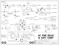
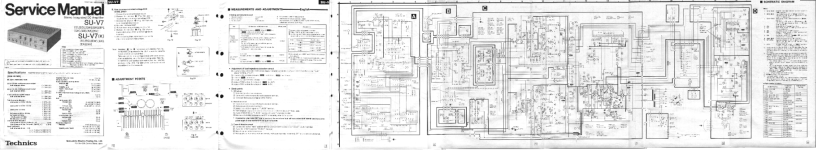
CIRCUIT SCHEMATIC DIAGRAM

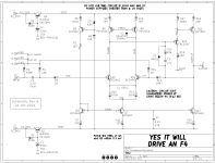
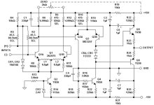
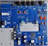
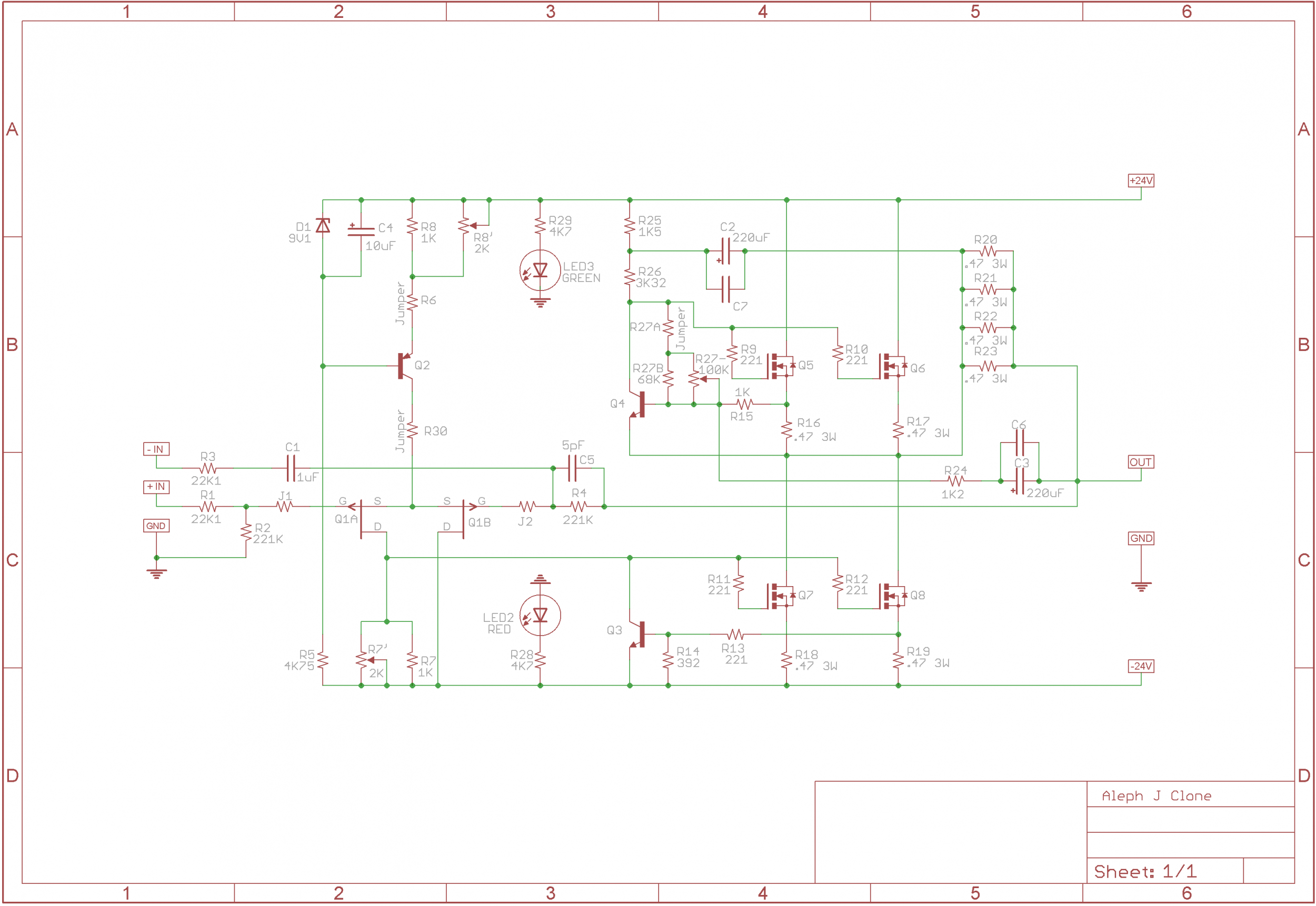
Figure 4 is the schematic of this PCB. The power handling "business end" of the circuit in on the bottom half of the page; the top half is merely timing and LED management.

The actual front panel switch connects at top left; it switches only 5V DC at 0.5 milliamperes. This ripples through some digital logic gates and produces a digital signal "TRIAC_B", which turns on triac T1 through opto isolator U4. When T1 turns on, it applies mains power to the transformer primary windings. Notice that triac T1 is series connected with an Inrush Current Limiter device, "ICL1".

Component ICL1 a 22mm diameter device made by Ametherm, whose surge energy rating is 125 Joules. For 115V applications I recommend part number SL22-20007, whose cold resistance is 20 ohms and whose max continuous current is 7 amps. Thus the inrush current when the ICL is at room temperature, cannot exceed (115 / 20) = 5.8 amps, and that assumes the transformer primary, mains fuse, and AC wiring all add up to 0.00 ohms of additional resistance. [For 230V applications I recommend the SL22-50004, whose cold resistance is 50 ohms and whose max continuous current is 4 amps.]

After a user-selected delay time (chosen by setting a jumper across one of 3 sets of pins on header P7), the inrush current limiting is bypassed. Digital logic signal BYPASS turns on MOSFET Q4, which energizes the relay RL1 and shorts out the (triac + ICL) devices. Now there is no extra resistance inserted; the transformer primary is connected directly to the AC mains.

The relay, the indicator LEDs, and all of the digital logic are powered from a tiny AC-to-DC converter module, U2. Today these are available which meet the sub-0.5W international requirements for standby power, and they are delightfully small and cheap. The big electronics distributors carry modules made by RECOM, Mean Well, CUI, and TDK-Lambda. However the TDK modules are quite expensive (3X!), and the CUI modules are in stock at DigiKey but not Mouser. Since Mean Well appears to have by far the greatest number units in stock and on the shelf at Mouser, that's the one I selected. Eventually I settled upon a 5V model, after realizing (a) 12V relay coils don't consume any less power than 5V relay coils; and (b) LED circuits actually do consume more power when operated from a 12V supply than from 5V. It's only obvious in retrospect. And that's why the board uses CD4000 logic chips -- they work at 12V (and 5V, and 3V, and 18V)

The AC/DC module output is made available at connector P5, in case other circuits within the chassis may need a low voltage housekeeping supply. For example, a "breathing" style LED. I strongly urge you not to connect either of the housekeeping supply terminals (5V_HOT, 5V_COLD) to the ground pin of other circuits. Treat it as its own, self-contained, floating 5V supply. If interfaces are required, use optoisolators between circuits connected to the housekeeping supply, and audio circuits connected to audio ground. That way you cannot pollute audio ground with noise or garbage from the AC-to-DC module. The module is rated for 400mA but I recommend drawing less than 300mA from the P5 connector, to avoid overload.

To soothe my paranoia about electric shock, I've included a 25 ampere bridge rectifier "BR1" between 5V_COLD and chassis protective earth. Now in the very unlikely event that the (class 2!!) AC/DC module develops a short between AC mains LINE and DC output Minus, the mains voltage is shunted straight to protective earth through a very high current pathway: BR1. Even if somebody had connected 5V_COLD to circuit ground, against my recommendations, it still gets clamped to a non-dangerous voltage through BR1.

A couple more details about the circuits connected to the front panel switch. Firstly, a very long debouncing time is conservatively applied (using resistor R2 and capacitor C1), compared to the measured timings of typical switch-bounce events, as reported in The Ganssle Group's debouncing article. After that, a Schmitt trigger (U3A) adds hysteresis. These two mechanisms filter out and remove switch bounces very effectively, and present clean square waves to the downstream logic. Secondly, flipflop U1B is a memory element which remembers the current logical state (am I on, or am I off?) when the front panel switch is a momentary contact device. The PCB user installs a shorting bar across pin header P6 when using a momentary switch on the front panel; this enables U1B. If there is no shorting bar across P6, U1B is disconnected and the non-momentary front panel switch controls On-Off behavior and timing.


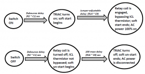
STATE TRANSITION DIAGRAM \ TIMING DIAGRAM

Figure 5 illustrates the sequence of events that occur when the equipment is turned On, and when the equipment is turned Off. As you can see, all delays are set by RC timeconstants on the PCB. Ambitious, self-confident DIY builders can modify these timeconstants, if desired, simply by changing component values.


INRUSH CURRENT: BEFORE AND AFTER INSTALLING SOFT START

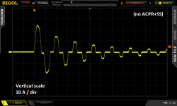
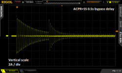
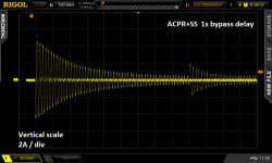
Figure 2 is the "before" measurement; it shows a stereo chip amp's power on event with no soft start applied. Figures 6 and 7 show the same amplifier, but with this PCB installed between the transformer primary and the AC mains.

In both Figure 6 and Figure 7, the inrush current has been reduced quite dramatically. "Before", with no soft start (Figure 2), inrush current peak was 24 amps. "After", with this PCB installed, inrush current peak was only 4.4 amps (2.2 vertical divisions X 2 Amps / div). (The horizontal scale is 100 msec / div as reported at top left in the Figures.)

In Figure 6, a shorting bar has been connected on header P7 from pin 1 to pin 2. This selects the "0.5 second delay" option for ICL bypass. You can see that when the ICL is bypassed, AC mains current jumps up. Because there is suddenly less total resistance in the transformer primary circuit.

In Figure 7, the shorting bar has been moved to pins 3 and 4 of header P7, which selects the "1.0 second delay" option for ICL bypass. Now the bypass comes later, and the up-jump of AC mains current is smaller.

These figures suggest, at least to me, that a setting of 1.0 second delay before bypass is desirable. And that's what I'll be using in my equipment. But other DIYers have the freedom to choose other settings, as they see fit. Thank goodness the jumper select options permit this easily.


CAUTION: I PREFER MY LEDs VERY DIMLY LIT ; YOU MAY NOT

Resistors R3 and R4 set the current flowing in the power-is-on and/or the power-is-off LEDs. I chose quite large resistances for these because I like dimly lit LEDs. You may want to experiment with the LEDs you plan to use, and to discover the resistor values which give the LED brightness that you prefer, with 5V supply voltage. Do this before stuffing and soldering them into the PCB, of course.


(optional tech info): MORE ABOUT INRUSH LIMITER JOULE RATING

The Ametherm ICL I have recommended in the Parts List, is rated for 125 Joules. Is this too little? Too much? Just right? Let's look at a couple typical scenarios.

Example 1: a chipamp with plus/minus 36V supply rails, using a diyAudio Universal Power Supply, whose PCB has a total of eight electrolytic capacitors. Each capacitor is 15,000 microfarads with a 50V voltage rating. Four of these capacitors filter the +36V supply, and four of them filter the -36V supply.

The energy stored in each of the four V+ capacitors, is 0.5 * C * V * V. Plugging in numbers, (0.5 * 1.5E-2 * (+36) * (+36)) = 9.72 Joules. Since there are four V+ capacitors, that's a total of 39 Joules for V+

Similarly the energy stored in each of the four V- capacitors is 9.72 Joules. {why? because (+36) times (+36) equals (-36) times (-36)} The total for V- is also 39 Joules.

Adding them together, the total energy stored in the PSU is 78 Joules. Which is comfortably below the 125J rating of the Ametherm ICL.

Example 2: the AB100 amplifier by Nelson Pass. This is a 100W/ch class AB amplifier with plus/minus 55V supply rails. Each rail has two electrolytic capacitors rated 10,000 microfarads and 63 WVDC. For each capacitor, E = 0.5 * C * V * V = 15.2 Joules. Since there are four capacitors, the total is 61 Joules. Comfortably below the 125J rating of the Ametherm ICL.

Although it's not written in the official published specifications on the seller's website, I have read here on diyAudio that the Intelligent Soft Start board from Neurochrome Audio, allows 250 Joules of inrush current energy (!!). Twice as much as the 125 Joules of this PCB. DIYers who believe they need more than 125 J (but less than 250 J) of inrush current energy, should consider the Neurochrome board to be a good possibility.


SUMMARY OF PCB CHARACTERISTICS \ FEATURES

  • Accepts low voltage, low current on-off switch
  • Accepts either momentary action, or rocker-toggle action, switch
  • Includes inrush current limiting ("soft start") with bypass
  • User selectable delay between power-on and bypass
  • Less than 0.5 watts standby power (when "power is now off" LED is omitted!)
  • Housekeeping 5V DC supply provided
  • 25A safety diodes between housekeeping supply and protective earth
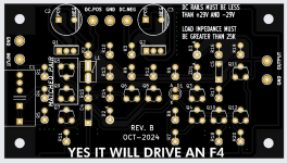
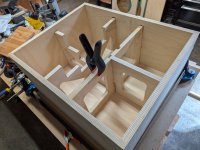
  • PCB mounting holes on 10 mm grid, matching Modushop perforated baseplate: Holes 60 x 90, edges 72 x 102 mm
  • 125 Joules max inrush energy

AVAILABILITY

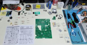
I have attached the Gerber CAD manufacturing files for this PCB; its unique identifier is H9KPXG . The suffix "-C" indicates revision C of the layout. Anyone can send the .zip archive of these Gerber files to a PCB fab and have boards made; the design is public domain and uncopyrighted. Use them however you wish. I hope if you end up with extra PCBs, you will consider giving them away for free, or selling them at low cost, to other diyAudio members.

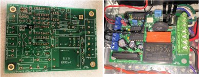
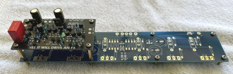
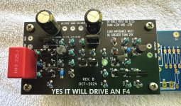
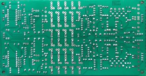
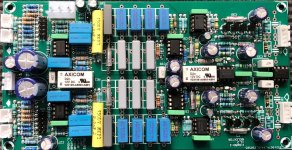
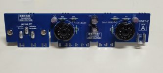
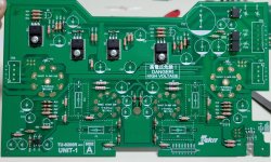
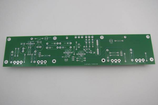
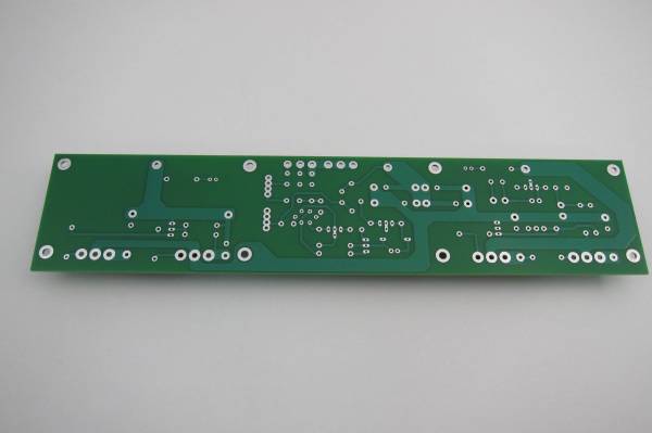
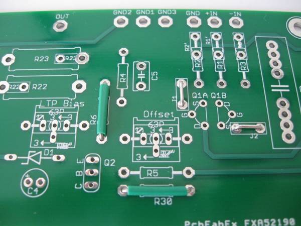
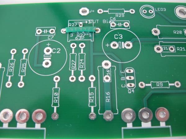
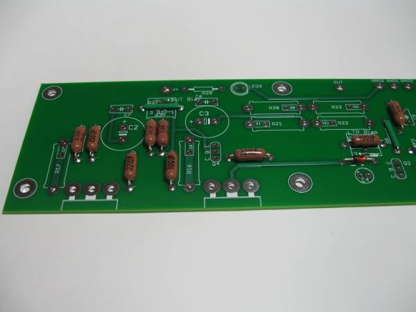
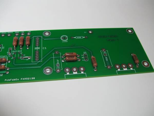
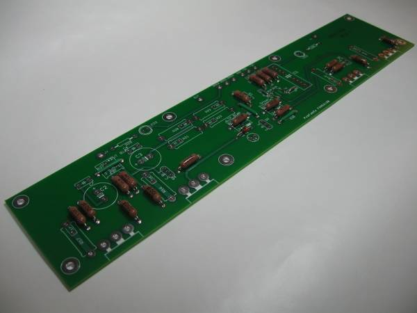
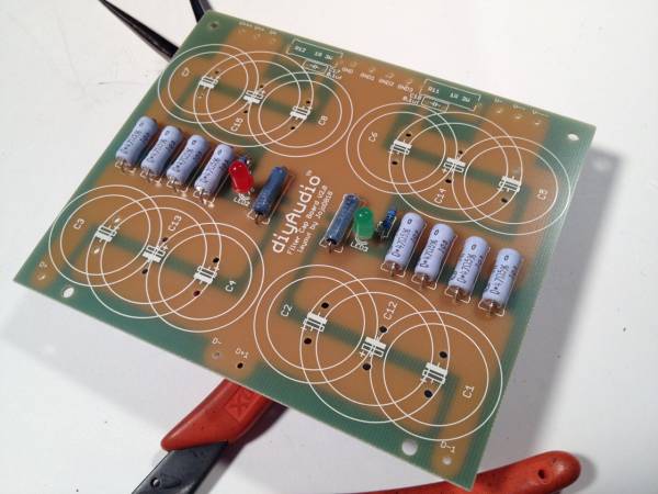
I strongly recommend that you have these built using BOTH 2-ounce-copper {double thick} traces, and also ENIG {gold} finish on the pads. An example is shown in Figure 8.

As of today, 23 May 2020, I have about twenty extra boards (2oz, ENIG) which I am willing to sell at my cost: USD 3.50 plus postage. One board per customer. In the present conditions I will be shipping to US addresses only. The required US Customs paperwork and face-to-face handoff for international shipments is, I regret to say, unacceptable to me. If you live outside the US and want a PCB, send these Gerber files to a PCB fab and have them ship boards straight to you. Give away or sell any extras.

A parts list is attached below. If a diyAudio member wants to turn it into a Shared Shopping Cart at Mouser.com, please go ahead with my best wishes. Just remember that 115V builders need one ICL part# while 230V builders need a different ICL part#.

_

Attachments

  • AV_switches_all.jpg
    AV_switches_all.jpg
    278.9 KB · Views: 10,633
  • No_ACPRSS.png
    No_ACPRSS.png
    34.4 KB · Views: 8,924
  • Cordell_softstart_schematic.jpg
    Cordell_softstart_schematic.jpg
    101.3 KB · Views: 10,135
  • schematic_ACPRSS.png
    schematic_ACPRSS.png
    35.5 KB · Views: 10,680
  • diagram_of_SS_timing.png
    diagram_of_SS_timing.png
    66.6 KB · Views: 10,537
  • with_ACPRSS_0p5_sec.png
    with_ACPRSS_0p5_sec.png
    50.4 KB · Views: 5,029
  • with_ACPRSS_1p0_sec.png
    with_ACPRSS_1p0_sec.png
    49.8 KB · Views: 5,527
  • BOTH_BOARD_SHOTS.jpg
    BOTH_BOARD_SHOTS.jpg
    844.7 KB · Views: 5,868
  • Parts_List_ACPR_SS.zip
    Parts_List_ACPR_SS.zip
    8.5 KB · Views: 1,555
  • H9KPXG_AC_mains_relay_SS_revC.zip
    H9KPXG_AC_mains_relay_SS_revC.zip
    95.8 KB · Views: 1,704

Yes It Can Drive An F4 -- an example circuit using tightly matched bipolar transistors

Last month at the Burning Amp Festival, I presented a little PCB called BJT Simple Matcher. That BAF talk, plus some photos, the matcher schematic, and the PCB Gerber file, are available on the diyAudio Forum (here). At the very end of the talk, I showed a little example circuit which greatly benefits from BJT matching, named "Yes It Can Drive an F4" (revision A).

A couple of small tweaks later the newest release (rev B), which I hope is the final release, is presented here in this thread. You can see a top view of its unpopulated PCB, and also the circuit schematic diagram, in the attachments below.

WHAT IS F4 AND WHY DO I MENTION IT HERE?

F4 is one of Nelson Pass's many FirstWatt amplifiers (link). Unusually, the F4's circuitry is arranged as a Unity Gain Buffer: although F4 provides enormous current gain, its voltage gain is only 1X. To get the maximum available output, 20V (peak), you must supply an input of 20V (peak). A large number of DACs, streaming devices, smart phones, and linestages are unable to swing their outputs to 20V (peak), so these are not a good match for the FirstWatt F4.

In fact, it is so rare to encounter a line level device which CAN swing its outputs to 20V (peak), that a snarky catch phrase has arisen here on diyAudio:
  • Yeah, yeah; but can it drive an F4?
I'm pleased to report that the little example circuit presented here, gives an affirmative answer. Yes it can drive an F4. Yes it can swing its output to ±20V (peak).

The board is designed to be installed within an F4 chassis and to use the existing F4 DC rail voltages, with NO modifications of the F4 power supply or the F4 amp channel. Just bolt in the new boards, one per channel, and wire them up. Done.

DOUBLE DECKER / PIGGY BACK MOUNTING OPTION

This circuit board is 50mm X 90mm; its mounting holes are 40mm X 80mm. Which is a perfect match to the left hand (or right hand) set of four mounting holes on the F4 PCB: 40mm X 80mm. Using spacers, you can mount it directly atop an existing F4 PCB, in Piggy Back (Double Decker) fashion. Please see the attached photographs.

An F4 amplifier channel board (blue PCB) has a Yes It Can Drive An F4 (black PCB) mounted directly above. The spacers in this picture are 20mm tall (M3 female, hex body, M3 male) but Amazon also sells 25mm tall spacers if you prefer longer. The male ends of the spacers replace the M3 screws which secure the F4 amp channel to its heatsink.

Of course, builders are free to mount their Yes It Can Drive An F4 boards wherever they wish, in whatever orientation they like; there's certainly no requirement to use the piggy back mounting scheme.

YOU CAN ZIP-TIE Q5 AND Q9 FOR BEST THERMAL CONTACT

I've arranged the PCB footprints of the matched pair Q5-Q9, so you can zip tie them together (face to face) before stuffing and soldering. Personally, I solder all six legs and then cut off the zip tie, before I scrub the board with 99% isopropyl alcohol to remove flux and grunge. See the attached photo with a thin red arrowhead that points to the matched pair of transistors.

After I'm all finished with IPA and other solvents, then and only then do I apply a dab of heatsink thermal grease between Q5 and Q9. Finally I zip tie them back together again. This time: forever.


CIRCUIT DESIGN OF YES IT CAN DRIVE AN F4

The main goals of this board are (i) to use and to exploit tightly matched BJTs, thanks to the BJT Simple Matcher from BAF 2024; (ii) to provide high gain and wide output swing -- 20V (peak) -- without any shenanigans or funny business on the power supplies. Just use the same ±23V rails as the amp channel, and be able to swing > ±20V on the output.

Goal (i) is met by choosing Q5 and Q9 in the circuit, to be a pair of tightly matched BC546C devices. The schematic asks for matching within plus or minus 0.3 mV; but in the real world you'd just test 30 or 50 NPNs and then select the two pairs with best matching (one pair for the Left channel, one for the Right). If you can't quite get 0.3 millivolt matching, it's not the end of the earth. And if you can get better than 0.3 mV matching, how lovely for you.

Notice that there is only one capacitor in the signal path: input coupler C1, a high quality polypropylene film capacitor by Wurth. C1 blocks any DC offset that may be present on the input ("J6") from polluting the circuit and its output.

The circuit is designed to drive an F4, which includes a pair of AC coupling capacitors between the F4 input buffer and the (large) F4 push-pull output stage. Therefore I have omitted a coupling capacitor at the output of Yes It Can Drive An F4; one is already installed, on the F4 amp-channel PCB. If anyone plans to use Yes It Can Drive An F4 in a completely different application, without an F4 amp-channel, they ought to think very hard about whether or not to AC couple the YICDAF4 output.


CIRCUIT DESIGN: PART 2

Yes It Can Drive An F4 is a two stage amplifier; the first stage is (Q5+Q9) with (Q6+Q8) current mirror load. The second "voltage amplifying" stage is (Q10+Q11) with Q12 constant current load.

Because it's a two stage amplifier taking its output directly from the collector of the 2nd stage, the circuit is not able to drive a low impedance load. But that doesn't matter since the F4 amp channel board is a high impedance load. It's 100K ohms, which is easy to drive, even for this scrawny two stage amplifier.

Bias current for the two amplifying stages is provided by reference current generator Q3, which drives a first current mirror (Q4, Q7) for the first stage, and which also drives a second current mirror (Q4, Q12) for the second stage. The bias current flowing in Q3 is set by zener diode ZD1 and emitter resistor R6:

IcollectorQ3 = Iemitter = (Vzener - VBE) / R6

Plugging in numbers, Icollector of Q3 works out to be approx 2.7 milliamps. Oh by the way, after enduring the tenacious, obstinate, unrelenting "recommendation" of member @6L6, I eventually installed a pilot light LED "D1" in this 2.7mA current path. When power is applied and current is flowing, this LED lights up and reassures you that the circuit board is properly connected to the supplies.

The first stage's bias current is just a resistor ratio multiplication of the reference current

IcollectorQ7 = IcollectorQ4 * (R7 / R11)

In the same exact fashion, the second stage's bias current is another resistor ratio times Ireference

IcollectorQ12 = IcollectorQ4 * (R7 / R20)

It's illuminating to notice that the second stage transistors which drive the output (Q11, Q12), can EACH swing almost all the way to their respective supplies, VTOP and VBOT. Other designs for the second stage constant current source (Q12 here), cannot swing nearly as close to the CCS supply. The current mirror topology is the king of this particular hill.

I have specified the ultra fast and ultra low capacitance diode 1N4151 for position D2. Its part number is exactly 3 greater than the ubiquitous junkbox diode 1N4148, and indeed these two diodes are blood brothers. Diodes whose final eTest measurements are excellent, fall into the 1N4151 bin. And the rest of the diode batch, the average and the mediocre, fall into the 1N4148 bin. I think it's a Good Idea for serious DIYers to have a bag of ten or twenty 1N4151s in their parts cabinet, for those occasions when a super fast or super low capacitance diode, matters. But if you disagree, if you don't want to spend 20 cents on a new diode part number, by all means please feel free to use 1N4148s instead. The circuit's performance will suffer only a very small amount.

FOR EXPERT DESIGNERS: GAIN-BANDWIDTH, SLEW RATE, AND INDUCTOR L1

Yes It Can Drive An F4 uses an extremely well studied topology with (at first glance) completely standard Pole-Splitting "Miller" compensation. James Solomon's 1974 tutorial article (link) models it quite well; we can populate Solomon's equations by inspection, yielding the circuit's gain bandwidth product and slew rate:

GBWP = { 1/[(1/gmQ5)+R10] } / C5

SR = IcQ7 / C5

thus GBWP = 9.0E7 radians/sec = 14 MHz

and SR = 100 volts/microsecond.

Now let's consider the effect of the inductor L1 in the "tail" region of the Long Tailed Pair, Q5-Q9. This turns out to be quite an old idea; according to Scott Wurcer here on the DIYA Forums, Richard Burwen of Analog Devices used it in 1966(!) on the hybrid discrete opamp "ADI121", shown in the attachments below. Later, Deane Jensen was able to take out a patent (US 4,287,479) on the same circuit. I've snipped out "Figure 3" of Jensen's patent and attached it below.

At very low frequencies, the inductor acts like a short circuit, so the emitter degeneration resistors R10,R13 are removed from the circuit at low frequencies. This has two benefits: (i) the noise contributed by R10 and R13 is eliminated at low frequencies; and (ii) the effective transconductance of the long tailed pair stage is greatly increased. In this circuit, gm rises from 2.4 millisiemens to 52 millisiemens -- a growth of 20X (26 dB). There is 26 dB more gain available at low frequencies, thanks to the inductor. That's 26 dB more negative feedback for distortion reduction. And, oh by the way, the Gain-Bandwidth Product increases by this same factor of 20X at low frequencies. It rises from 14 MHz to 280 MHz. Cowabunga.

I encourage expert readers to derive expressions for "f1" and "f2" (the pole frequency and the zero frequency introduced by inductor L1). I think you'll be pleasantly surprised at how high these break frequencies actually are. I think you'll be delighted at how much extra gain / distortion reduction is made available at 20 kilohertz. All for the cost of a single inductor.

DON'T DO ANY OF THE FOLLOWING, THEY ARE BAD IDEAS

First: I have set the gain of Yes It Can Drive An F4 to 20 volts per volt (+26 dB). An input of 1 volt (peak) produces an output of 20 volts (peak), which is the maximum input signal allowed by an F4. Don't attempt to change the gain unless you really know what you're doing. If you need someone to help you change the gain, that means: you don't really know what you're doing. Stop now.

Second: Don't reduce the gain below four volts per volt (4.0X = +12 dB). If you do, there is a very good chance the circuit will oscillate, blowing your tweeters and perhaps also destroying the power transistors on your F4. If you need gain less than 4X, switch to a different design without this limitation.

Third: Don't put this circuit into an amplifier that is wildly different from the standard, stock F4 as documented by Nelson Pass. In particular, don't run at supply rail voltages greater than 29 volts. Neither the transistors nor the capacitors will survive at higher voltage; you will need to design a new circuit with different components and possibly different topology.

Fourth: Don't drive a load impedance less than about 25 Kohms. If you NEED to drive a lower impedance load, you will need a different circuit. This one is designed for the F4 which presents a high impedance load.

Fifth: Don't experiment with other values of inductance. Either use 680 microhenries (choose an inductor whose self resonance frequency is the highest Mouser will sell you), or else omit the inductor entirely and don't stuff or solder anything into the L1 footprint on the board.

Attachments

  • PCB_top_view_revB.png
    PCB_top_view_revB.png
    211.8 KB · Views: 1,509
  • raster_scan_schematic_revB.png
    raster_scan_schematic_revB.png
    130.8 KB · Views: 1,683
  • stacked_oblique.jpg
    stacked_oblique.jpg
    297.3 KB · Views: 1,992
  • thermally_coupled_BJTs.jpg
    thermally_coupled_BJTs.jpg
    451 KB · Views: 1,017
  • Jensen_Fig3.png
    Jensen_Fig3.png
    326.9 KB · Views: 1,034
  • Yes_It_Can_Drive_F4_schematic_revB.pdf
    Yes_It_Can_Drive_F4_schematic_revB.pdf
    33.2 KB · Views: 382
  • PartsList_Yes_ItDrives_F4_revB.zip
    PartsList_Yes_ItDrives_F4_revB.zip
    4.2 KB · Views: 204
  • Gerbers_Yes_itdrives_F4_revB.zip
    Gerbers_Yes_itdrives_F4_revB.zip
    105.5 KB · Views: 202
  • stacked_daughter.jpg
    stacked_daughter.jpg
    462.3 KB · Views: 1,520
  • ADI121_Richard_Burwen_1966_inductors.jpg
    ADI121_Richard_Burwen_1966_inductors.jpg
    94.2 KB · Views: 1,342

Car sound deadening material for house wall vibrations?

Hi all,
is anyone using car-sound deadening materials in home construction to reduce vibrations?
I am talking about stuff like "Dynamat", "Noico" and many others, self adhesive material.

I have an interior basement wall that vibrates a lot due to HT subwoofer.
The wall is build of 1/8" panelling (the 70's style old house) on 6" studs.
It is a sound pressure created vibration, not direct transfer from the sub.

I have access to the wall from both sides and can get to the panels from the inside. I'd prefer not to change the panelling to drywall, hence my question about sound/vibration deadening materials.

Thanks in advance!

Suggestions for the Best Mid-Woofers?

Hello all! After reading many threads here for years, I wanted to give it a try. So, this is my first post and attempt at building speakers!

I love JBL speakers and horns, especially the 4349 and 4367. I have a relatively small living room, so I’ve decided to build a 60-80L vented box with a 12-inch horn and a 12-inch woofer. To match the directivity, I plan to cross the woofer between 700-900 Hz with an LR4. It will be an active speaker, so the crossover is digital. The F3 is important, but as long as it’s below 45 Hz, I probably won’t use DSP to boost it.

So far, I’ve found the Faital 12RS430 and Acoustic Elegance TD12S. I’m willing to pay a premium for two drivers, but I really want to do something special. What are some of the best woofers I can buy that suit my project? Especially with low THD.

Any help is greatly appreciated!

Turntable Preamplifier Noise Problem

I built Doug Self's MM/Mc turntable preamp. This circuit is the Elektor premaplifier 2012 circuit, but there is an increasing noise parallel to the volume pot. As I open the volume potentiometer, the noise increases. I took the power supply completely out of the box and the problem has not improved. I replaced the signal cables with shielded coaxial cable and the problem persists. I am trying it as MM only. I have attached pictures and a video of the noise. Please help.

Attachments

  • WhatsApp Görsel 2025-05-23 saat 19.27.15_8c4379c3.jpg
    WhatsApp Görsel 2025-05-23 saat 19.27.15_8c4379c3.jpg
    221.1 KB · Views: 143
  • WhatsApp Görsel 2025-05-23 saat 19.27.15_027111c8.jpg
    WhatsApp Görsel 2025-05-23 saat 19.27.15_027111c8.jpg
    221.1 KB · Views: 135
  • WhatsApp Görsel 2025-05-23 saat 19.27.15_589476ce.jpg
    WhatsApp Görsel 2025-05-23 saat 19.27.15_589476ce.jpg
    274.6 KB · Views: 134
  • WhatsApp Görsel 2025-05-23 saat 19.27.15_d2f1dd41.jpg
    WhatsApp Görsel 2025-05-23 saat 19.27.15_d2f1dd41.jpg
    221.1 KB · Views: 137
  • WhatsApp Video 2025-05-23 saat 19.27.16_7e8d4c86.mp4
    1.9 MB
  • WhatsApp Görsel 2025-05-23 saat 19.59.21_e078f780.jpg
    WhatsApp Görsel 2025-05-23 saat 19.59.21_e078f780.jpg
    231.2 KB · Views: 138
  • WhatsApp Görsel 2025-05-23 saat 19.59.22_021c4d1b.jpg
    WhatsApp Görsel 2025-05-23 saat 19.59.22_021c4d1b.jpg
    274.6 KB · Views: 135

8" midrange vs. 4" midrange (besides the obvious)

Hi,

Obviously a 8" midrange can be louder (and I'm guessing less harsh) than a 4" midrange, but how might the "speed/accuracy" (or transient response), especially in the high-mids, compare (appropriately-sized sealed chamber for each driver)?

More specifically, something like an 18 Sound 8M400 8 inch midrange vs. a Dayton Audio PC105 4 inch "full-range but you can use it as a midrange" (both 8 ohm versions).

The 4" is currently being run 500Hz-3.5KHz between a sealed-enclosed 12" woofer and the tweeter, but I'd want to run the 8" 200Hz-3.5KHz.

Looking forward to hearing back 🙂

NP Speaker Protection Circuit

Can someone explain how the output is grounded and what is grounded? How would this be wired up? I'm not getting how the output shorted doesn't fry the amp output.
Is it sending the speaker positive to ground? I looked at 3 other circuits and articles to make sense of it. One of the circuits in the store looks like it disconnects the + and - outputs entirely, but seems like people don't like the signal going through the relay. That correct?

Th protection circuit found in the diy store. https://diyaudiostore.com/products/nelsons-psu-filter

GAYA2-Final, finishing the unfinished after 15 years

I designed and built my current system during 2006, it is a WWMT with Scan-speak 21W8555-01 8" woofers, Accuton c2-6-78 midrange and Accuton c30-6-24 tweeter, height some 110cm. Due to other priorities i had to stop spending time on speaker design and thus remained some unfinished work on my speakers as of 2007.

opstelling.jpg

Current set up in living-room, 5.3m wide and quite asymmetric, to the right there is another small room ;-)

A few of years ago i started to look into this matter of speaker design again, studied the publications on the subject (Toole, Griesinger, Johnston, diyaudio.com, etc) on design as well as sound reproduction and played with 6mm felt sheets to reduce the unwanted diffraction effects, not much improvement.
Last year just as a "just do it" step i took some absorption panel (cotton, shredded jeans, very difficult to cut), and quickly made something and put it on the speakers.
Some difference!, most striking was the timbre of voices, instruments, stayed much more constant across the room, also more involvement.
EcoAbs-Baffle-01.jpg


I got intrigued, and this spring re-assembled measurement rigs, made a turntable, and together with Arta and VituixCAD started to get experienced again in measuring and analysis. I decided to start basically all over again, be it with the assembled enclosure with drivers as a given. The passive crossover, and any physical adaptations for the edge diffraction, be it within the limitations of the front of the speaker, are to be engineered from scratch.

The objectives:
• Flat anechoic on-axis response, note: will require tilting the tweeter forward as baffle is tilted backwards.
• Smooth off-axis response & early reflections response and sound power & DI
• Distortion focus, be it with given drivers. Note: Filter choices can influence distortion.
• Spurious noises (already non-existent sofar, but the metal grilles are suspect)
• From my experience and listening preference:
- Crossover frequencies: ~435 and ~3465 Hertz (based on the discrimination bands of our hearing, reduction of doppler effect distortion)​
- Sound stage aka dimensionality,​
- separation of the individual voices/instruments​
- left-right & depth​
- Mostly playing at lower levels (< 80 dB), occasionally also louder.​
- Timbre constancy in room at various listening positions.​
- Envelopment (being there sort of independent of the actual living room)​
- Engagement, does the music make me engage, does it trigger emotions.​

This all gave me a starting point in my loudspeaker project, named:

GAYA2-Final: Finishing the unfinished after 15 years

As the name implies it is to finish what I started in 2005 and had to stop end of 2006, engineered to the current state of the art.
Key to being successful is the following: “Through measurements to knowledge” (door meten tot weten) , the quote of Heike Kamerlingh Onnes.

This principle is fundamental, therefore from the desktop research:
  • Arta, Limps and Steps for measurements and some of the analysis.
  • Calibrated microphone
  • VituixCAD for the crossover design and simulation, taking a holistic view on and off-axis and step performance.
  • And very important: Listening test, not only to correlate sims with the reality, also to achieve my perception based objectives.

And when done to incorporate what currently is possible for room corrections in the currently well-developed digital dimension of sound reproduction. I already have purchased Uli’s Acourate Pro and Mitch’s Hang Loose Convolver for this aspect.

The start:
I learned the tools by exercising measurements, study forum and article/book publications and perform analyses to fully understand them, before beginning with the real thing.
To cut a long story short: See also the thread Tmuikku started: https://www.diyaudio.com/community/...sover-and-tilt-experiment.388389/post-7097857

The outcome , quite humbling, is first of all the absorbing matter did make a difference, but also I have to get my measurements correct and repeatedly consistent, including getting rid of some DC error / very low frequency rubbish and the floor and ceiling reflection to get a decent gate in msec. Last but not least, my current baffle-shape for midrange and tweeter needs serious improvement (no surprises there 😉)

So back to the drawing board.

And not to forget enough space around the speaker during measurements, which means temporarily re-arranging the living room, thus only possible when I am alone and having enough time. 😉

Technics SU-V7 bias problem

Hello,

Had this one in my office for a while. I did a full recapping job, calibrated most of the things, per service manual, then ran into a bias problem and left it there.
6 months after picking it up where I stopped.

What I did:
  1. all electrolytic capacitors changed​
  2. both Thyristor replaced (were damaged)​
  3. Supply voltage adjustment & check done and working
  4. Adjustment of load impedance detection circuit done and working
  5. DC balance calibrated and working
  6. Protection circuit calibrated and working
  7. Overload detection circuit calibrated and working
  8. replaced output relay
  9. cleaned controls and potentiometers

The problem, adjustment of Ico (bias).
The right channel is nicely biased @ 2mV, as the manual suggests. Everything works smoothly with it.
The left channel, oh boy oh boy... Looking at the schematic, my Q317 collector measures 0.5V, Q319 collector measures -3.3V, with respect to 0V. Everything after that is not even close to the values in service manual...
My thought, I have one channel working, and I don't have these transistors in stock, let's change transistors and diodes from one channel to the other and see.
I exchanged (left channel with right channel): Q317, Q319, D305, D307, D311, D309, Q321, Q331, Q333, Q327, Q329. Of course, I didn't replace everything just like that.
I check the bias adjustment after each exchange. The thing is the same... I also checked resistors, all good. I resoldered most of the left channel. Still the same. I measured all ceramic capacitors on the left channel, all good.

The amplifier works, it passed the signal, but after few watts of power, as expected, the left channel waveform (the bottom sine wave) starts to distort.

Any ideas? Any help will be appreciated. Maybe I'm missing something, or everything 😀

Ciao,
John

EDIT: VR301 is also replaced with new trimmer, Z301 power resistor has been replaced also. Schematic is attached, so you don't have to search through manual 😉 The voltages before bias circuit (Q301, Q303, Q309, Q313, Q315, Q311) are correct.

Attachments

  • Technics_SU-V7-schematic.png
    Technics_SU-V7-schematic.png
    721 KB · Views: 89

Very simple MOSFET preamp/driver

I built this circuit back in the year 2002 and I used it as a driving stage for my class A power buffer PM-A1 (gain 1x, 30W/8ohm). It was working very well with quite good parameters, as can be seen below.

MOSFET_PRE.png


(D1 is a Zener diode 6V8)

MOSFET_PRE_FR.png MOSFET_PRE_THDN.png

I am showing above the THD+N plot (1kHz, BW40kHz) to include noise part as well. This is often omitted, unfortunately.

Loopgain stability is perfect, with 87° phase margin.

Best electrolytic capacitors

We can't always afford polypropylene capacitors, much less
Teflon (tm), so we often make do with electrolytics when
we need those higher values.

There's all sorts of caps out there with claims to being better,
and they certainly are more expensive.

My favorite is the Elna silk capacitors, available from Digikey,
and really cheap. The measure spectacularly, sound great,
and the manufacturer's translated description of why they
sound better is a Babelfish classic.

So before you run out and spend a lot on the highly hyped
spendy caps, try the Elna silk caps.

There's hemp in them, too.

😎

DIY D-class amplifier+digital broadcasting all-in-one machine

The post in the newcomer reporting area has been closed

This device is purely a personal DIY, and all the components come from online shopping. There is only one device, and I am not some kind of equipment supplier.

Basic idea:
TPA3255(600w) x 6 + 50V1000W + 15V+/- Switching Power + LT3045/LT3094 + 7*JRC5532DD + miniPC + Terratec 7.1USB sound card + Roon Server
A.png

Speakers for a "Kissa" music lounge

A custom semi-PA speaker system with a nod toward vintage JBL. It was a fast-tracked design & build for a local pop-up "kissa" music lounge made possible by a group of mostly volunteer collaborators. The need was for a system in a ~5000cf cafe: Good to 40Hz, linear enough for high fidelity to 15kHz, sound good at 90~95 dB SPL (1m) as well as up to 110 dB for the "nightclub" sessions.

The speaker project was green-lighted at the end of March for opening night on May 23. Installation would occur in the 4 days before. A very short timeline. So with tariff wars, no imports, only Canadian sources of components, primarily Solen, and whatever I already hand in hand.

I studied catalogs & databases for a few days in April, scoured my own shelves, and came up with a plan with mostly SB Audience components from Solen:

B-52 PHRN-1014 1" Horns -- 90x40 directivity, low 600 Hz cutoff, long discontinued but I had a pair on my shelves.
They were the most suitable horns for this project. I also had Eminence N151M-8 1" Ring compression drivers and B&C DE250-8 1" Polyimide Horn Driver. But experiments with these CDs on the 14x10 horn did not impress me, so took a chance on the SB Audience ROSSO-44CDN-PK compression driver. This proved to a lucky exceptional match with the 10x14 horn.

No way I was going passive with this. A miniDSP 2x4 HD was in hand. It would accelerate XO/EQ development, & allow finetuning the system for the venue.

SB Audience NERO-12MWN700D is a recently released 12" high efficiency pro “mid-woofer” with neodymium magnet. FR looked good to past 1kHz. Its 54 Hz Fs and modest 7.3mm Xmax looked like serious limitations, but the 18mm peak-to-peak Xdamage was somewhat assuring. A 30 Hz steep high pass crossover filter, 48 or 24 dB/oct, could be applied for protection; fingers crossed that wouldn’t impact sound quality.

WinISD calculations showed a 2 cf box tuned to 47 Hz for flat response to around 50 Hz. That was better than the QB3 alignment in WinISD, with Vb of 1.55 and port tuned to 54 Hz. DSP could extend this down a bit. The maximum SPL predicted by WinISD at 50 Hz with the 150W available was 115 dB, which seemed plenty though optimistic.

After development on my PC, I built the enclosures, tested & finetuned the system with horns mounted externally on shock absorbers (which definitely helps retain clarity at high SPL). About 1.5 sheets of 4x8' 3/4" G1S Chinese-made BB plywood was used. Cheaper than the Russian 5x5'. The XO was LR4 at 1kHz after PEQ applied to smooth both driver responses. There was about a 6-7 dB boost to flatten F3 response to ~38Hz, and some other relatively minor tweaks. Further improvements might have been possible, but time was very tight, so after I determined the subjective performance to be pretty darn good, several other Kissa team members auditioned and deemed them worthy.

Then the drivers were removed & boxes handed off to another group member who who applied a "micro-cement" finish with gobs of blue dye. The box came back to me 10 days later, at which point it was rush rush to get them installed and running at the cafe.

The REW FR curves for left and right speakers are the only ones I managed to measure on the day before the opening. With others working on cabinet installations, counter renovations, new curtains, and new ceiling damping panels, plus the constant noise of the refrigeration units in the cafe, it was very difficult to measure anything. The mic position was ~2m, with 10 deg of vertical/horizontal axis.

The only PEQ change made after these sweeps was a 4 dB Q=3 boost at 14kHz to counter the falling response. That was perceived as an improvement by everyone who heard the difference.

The end result was successful: Many participants who attended the "curated musical exploration" sessions over two weekends praised the sound, calling it the best they'd heard. Some whose hearing was damaged said it was the first time in years that they'd heard music so clearly. This probably speaks to the relatively low sound quality of audio systems most people are exposed to routinely. Still, I have to say the speaker sound much better than I'd expected in the space. Bass, especially, is quite powerful & extended, to a bit below 40Hz. Dynamics are excellent, and they apparently did fine in the 4 nightclub sessions as well.

For now, the speakers and dedicated XO/amps remain at the cafe, with the "kissa" project taking a hiatus. The owner is delighted with the extra traffic & business to the cafe & his restaurant next door, and with the option to use the system routinely.

Attachments

  • PXL_20250412_231941610.MP.jpg
    PXL_20250412_231941610.MP.jpg
    470.7 KB · Views: 119
  • PXL_20250413_164845924.MP.jpg
    PXL_20250413_164845924.MP.jpg
    423.8 KB · Views: 89
  • PXL_20250415_001847782.MP.jpg
    PXL_20250415_001847782.MP.jpg
    465.8 KB · Views: 91
  • PXL_20250424_182707359.MP.jpg
    PXL_20250424_182707359.MP.jpg
    400.4 KB · Views: 93
  • PXL_20250425_190718961.MP.jpg
    PXL_20250425_190718961.MP.jpg
    359.8 KB · Views: 89
  • PXL_20250515_193429650.MP.jpg
    PXL_20250515_193429650.MP.jpg
    305.3 KB · Views: 95
  • PXL_20250515_220319616.MP.jpg
    PXL_20250515_220319616.MP.jpg
    461.6 KB · Views: 114
  • PXL_20250524_191627197.MP.jpg
    PXL_20250524_191627197.MP.jpg
    563.2 KB · Views: 125
  • PXL_20250524_233246349.MP.jpg
    PXL_20250524_233246349.MP.jpg
    523.6 KB · Views: 125
  • IMG-20250529-WA0014(1).jpg
    IMG-20250529-WA0014(1).jpg
    166.2 KB · Views: 99

Quasi Complementary ECX10N20 Amplifier with good performance

I started this thread for IRFP240 Quasi: https://www.diyaudio.com/community/threads/quasi-irfp240-amplifier.428495/
Now I use another MOSFET transistor for better qualities.
I use Exicon Lateral ECX10N20 for this thread.

The benefits are three:
1. Somewhat less distortion, THD 0.005%
2. Higher max output, 25 Watt in 8 Ohm
3. No need for MOSFET protection diodes, are already built in

Here is the schematic. Enjoy 🙂
Quasi ECX10N20 24V_01.jpg

Resonaces in 4 BP

If I clog up the high side of my sixth order parallel band pass i I still get those quarter wave resonances ?

Are they based on the 120 cm resonator (it’s a big vented reflex) ?

(Video by @maxolini )

Attachments

  • IMG_4436.jpeg
    IMG_4436.jpeg
    910.8 KB · Views: 55
  • att.ViouduzNTfQaR_OPNmjpN9Qr9kb2kuJtIixKyp3hxMQ.jpeg
    att.ViouduzNTfQaR_OPNmjpN9Qr9kb2kuJtIixKyp3hxMQ.jpeg
    80.6 KB · Views: 60
  • C1A5AEA3-C340-4282-90F5-B6C81B6BDD14.mp4
    2.9 MB
  • att.EMWO2LPOdO9eu7Gk2E4leBUKUYfapVN28aP0Dx4U9NQ.jpeg
    att.EMWO2LPOdO9eu7Gk2E4leBUKUYfapVN28aP0Dx4U9NQ.jpeg
    48.7 KB · Views: 53
  • att.2NlXptdm5nLwBiEkDxpVk0hujRn_u1cxu-TQWJTB0zo.jpeg
    att.2NlXptdm5nLwBiEkDxpVk0hujRn_u1cxu-TQWJTB0zo.jpeg
    56.2 KB · Views: 59

Analogue approximation to Linkwitz Transform (for tweeter)

As discussed here I have implemented a good approximation to a 4th order LR to a Seas tweeter by estimating the existing Q and frequency, and using an LT to raise the cut frequency and make the response align to the 2nd order Butterworth - and then overlaying a further second order.

This gives a pleasing result with my miniDSP crossover.

I'd like to use this technique again - but with a conventional (if external) crossover. Is there any software that would do this, or should I just try to replicate the response by simply fiddling in XSim with trial and error? I don't need to introduce any gain, its all attenuation and raising the cut frequency.

(And yes that leaves me with the Z offset to mess up phase, which I deal with in pure delay in DSP - but it will be a starting point, and for some tweeters with very low Fs, I might still look for around 1.2kHz 4th order - like my Wavecors for example - which should reduce the phase error somewhat).

Does distance between drivers really matter?

There are a lot of recommendations to keep the distance between speaker drive units as close to each other as possible, especially the drivers for higher frequency, because a point source configuration is preferred.

Let’s look at these “Avalon” speakers. They are two ways system comprising a woofer and a tweeter per cabinet. But, as can be seen, those two drivers are positioned so far from each other, and work together (crossover point) at high frequency as a typical two-way system. So, does the distance between drivers really matter?

Or, in fact, the statement above is true, but Avalon has applied the special techniques on them. Is there anyone used to reversed engineering these speakers? Could you please advise us what are the magic/secret designs—the special approaches/techniques, e.g., using higher-order crossovers with large overlap, or using lower-order with a lot of EQ circuits including baffle step correction, etc.?

IMG_0416.jpeg
IMG_0415.jpeg
IMG_0414.jpeg

Hitachi tuner FT5500 MKII display out by +0.05MHz

Hi All. I have the 5500 Mk2 tuner that works perfectly and sounds good, but every "locked" station shows a frequency of +0.05MHz. QUESTION, is this just a case of the frequency counter of the display needing a fine adjustment or does more complex adjustment need to be done? I realise it would benefit from a total accurate realignment, but cannot find anyone in the UK that can do it. If it is just the frequency counter how do I adjust this please? .....Thanks for reading.

Measuring O/P BIAS current

Hi All. I just cannot get my head around this BIAS measuring of the L12 Amp to enable to set the bias trimmer! QUESTION: What VOLTAGE should I set across the combined emitter resistors please in the shown example below to achieve a bias current of 40mA? It's a BASIC OHMS Law calculation, but do I use the SUM of the resistors (0.44 Ohms) or just the single value of 0.22 Ohms?. ... In my amp the emitter resistors are in fact just 0.1 Ohms.... Perhaps I should measure each collector voltage separately to ground across it's single resistor instead? Many thanks for your help.

1749304511069.png

I love the Elekit TU-8200R Amp with TU-8500 Pre-Amp.

Good morning and happy Monday, y'all! I hope everyone had an excellent Thanksgiving this year. 🙂

Before I get into it, I want to thank Victor Kung @ VKAudio for his assistance and patience in answering my questions, particularly about Capacitor upgrades. His knowledge is invaluable and he's a good guy to have in your corner when you need help. I also want to thank TubeDepot which is where I purchased my kits from. Honestly, if I'd have spotted Victor's store earlier, I probably would have purchased directly through him. However, I have no complaints whatsoever with my transaction as TubeDepot has always provided me with great products at fair prices.

With that done, I'll move on.

I've been an audiophile for more than 35 years. Music is the one thing I can depend on to get me through each day. It make a bad day turn good and make a good day even better.

Now, I'm not an audiophile in the "I own a set of Infinity IRS-V speakers powered by 3 Macintosh Amplifiers" sort of sense. I would love to be there, but that's a financial commitment I'm simply just not able to justify. However, I absolutely love how a quality sound system can bring out deep emotions, stir up memories of people and places, and transport you to another time. It has that much influence.

Until recently, I've always been a solid state kind of guy. Part of the reason is that the generation I grew up in was on the leading edge of Transistor technology with vacuum tube well on their way out the door. In fact, about the only thing you could buy with vacuum tubes in the '80s were guitar amps, and even those were rapidly declining in favor of the less expensive, sturdier solid state equipment. I do remember as a younger child, my parents and grandparent having old vacuum tube equipment, and I would spend many hours listing to records on this equipement. This probably set my mental bar for audio quality.

I guess that the other reason I was into solid state was that I was very big into car audio in the '80s and '90s, and there just isn't any place for vacuum tubes in car audio! I see there are companies that actually specialize in this kind of equipment, but that all seems a bit gimmicky. LOL

A couple years ago, I really started getting back into the idea of analog sound. I have always love vinyl and actually had an impressive collection until our house burned down in 2015 and we lost everything. Almost 40 years of collecting lost forever. Anyway, while I enjoy the analog nature of vinyl, it's always been through solid state amplification. Not that it was bad... In fact it's quite the opposite. It's just that I always did feel like something was lacking. Some level of depth or warmth that I remembered from my childhood that I just couldn't seem to reproduce. So decided to start looking around at what's available.

Vacuum tube audio equipment is clearly big business these days, with companies building preamps, amps, active crossovers, and other stuff that vary in range from hundreds to hundreds of thousands of dollars. The array is as dizzying as it is almost endless. Reviews leave you with more questions than answers, and almost anything with decent reviews will empty your wallet in short order. But the question at the end of the day is, "Is a $10,000 amplifier any better than a $1,000 one?" I'm sure that at the end of the day the answer would be, "Yes, the $10,000 amp is better." But the next question would logically be, "Is it $9,000 better?" In many cases the answer would be solidly, "No."

With this in mind, I started looking at many different amplifiers in the "under $5,000" range. There are a number of what I presume to be quality products on the market in this price range, but still couldn't make heads or tails of what was actually worth dropping my hard-earned cash on. Oddly enough, while researching different amplifiers, I came across a DarkVoice 336SE headphone amplifier in a pawn shop and scooped it up. Even before I plugged it in and turned it on, I was already looking at reviews, schematics, and upgrades to this unit. My first 20 hours into it, I had already order a variety of tubes so that I could start rolling as time permitted. I do realize that this little amp met with mixed reviews, but was mostly positive. I also discovered that there were some very easy improvements that could improve the quality and reduce the idle noise of the amp. I, personally, love this little amp. It brought back that sound I so vividly remember from my youth. The depth and presence that I felt I was missing was restored. Even with high quality digital recordings, there was a sonic improvement. That's was it. I'm now hooked on tube amplifiers!

I figured the best place to start would be at the bottom of the chain and slowly work my way up. After digging around for several months, I came across the TU-8200R Amp kit along with the TU-8500 Pre-Amp kit. I found it intriguing as it was a full-on, build-it-yourself sort of kit that came with everything. The reviews on it were outstanding, and the documentation on component upgrades was well defined and easy to follow. The only pitfall was that some of the upgrade components were no longer available, such as the AMTRANS components, but c'est la vie. The biggest improvements seemed to come from using Mundorf coupling caps and Lundahl transformers anyway, so that was what I opted with for the final build. Tube rolling will come later. Ordered through TubeDepot and then waited for the brown Santa to show up in his trusty delivery van.

I did my process a little backwards, starting with the pre-amp first as I was waiting for my Lundahl transformers to come from VKAudio. Out of the box, this thing is a solid work of engineering. The chassis was remarkably clean in design and fit together well. I may, at some point, disassemble and have the chassis powder coated a different color, but it's great as it is. The PCB is laid out very well, all the components were grouped in nice, organized baggies, and the instructions were very clear to understand. Now, I'm an electronics engineer by trade (digital, not analog), so following a schematic and PCB layout is a simple thing for me. Not to mention that I have a helluva soldering station. PCB assembly and soldering didn't take long, and within a couple hours I had the whole thing put together. Slapped in the J/J tubes, connected my Technics 1200 turntable to it, and hooked it up to an old Pioneer SX-980 with Kenwood KL-777A speakers and then let 'er rip.

I let the pre-amp run for about 2 hours just to let things settle in and then dropped Tom Petty on the platter. Even with the tubes barely even run, the difference was immediate. The sound was warmer with vocals that were more in the foreground. I played this album and then moved on to my next favorite, Pink Floyd - Wish You Were Here. Shine On You Crazy Diamond (Parts 1-5) is my quintessential sound system test. For me, this track reveals the soundstage and depth of a sound system, or even the capability of individual components, and let me tell you, the TU-8500 did not disappoint. I went with this setup for several days, and with each passing hour the pre-amp continued to provide subtle improvements in sonic and tonal quality. I now realized I needed to get the amplifier built!

Thanksgiving intervened and I had to do all that family stuff. While I always enjoy being with family, I was quietly preoccupied with wanting to put the amp together. Our office was closed for Black Friday so I headed in and began the process of assembling the amplifier in peace and quiet. Again, all the details were impeccable and assembly was completed in a matter of hours. I'm a bit of a perfectionist, and since the tubes are exposed in this unit, I spent a little extra time making sure that the tube sockets were level and even. Unfortunately, during my final assembly of all the PCB units, I forgot to solder the bridges on the bottom of the input/output board which left me a little perplexed when I fired up the amp and had no sound. A few muttered curse words and 45 minutes later, all was good.

I've always heard from people that 10 watts of power from a tube amp is like 50 watts of power from a solid state amp. I always took these comments with a large degree of skepticism since I've always argued that "Watts is watts." I guess that it's true that wattage is a pretty stable measure of audio output. But let me tell you right now... This little amplifier that only runs 8 watts per channel sounds better than my 100 watt per channel Onkyo receiver (in stereo mode) running through a set of B&W 603 S2 speakers! Of course, the Onkyo running in 7.1 will simply outmatch almost any 2 channel amplifier for range and soundstage, but in 2 channel mode I would take the little tube amp every time. There is no absolutely no hint of hiss or hum at idle with no input, even with headphones on. It is dead quiet until you feed the signal back into it and then it just fills the room.

I just couldn't believe the quality of the sound the TU-8200R produces at a pretty solid listening level. It's certainly loud enough that I can feel immersed in the music, and that even with the TU-8500 pre-amp on a flat 1x gain on the inputs. I haven't even turned it up to 3x yet, and from what I've read so far, the amplifier can certainly handle the higher input levels without becoming too distorted. I may give that a try tonight and see how well it handles. I expect it may pick up some signal noise, but I can't say until I give it a spin.

As an aside, the amplifier works great with a set of high quality, high impedence headphones. My Sennheiser HD-650, which works fantastic with my DarkVoice 336SE, sounds fantastic with the TU-8200R. Of course, you don't buy an amp like this just to plug in a set of headphones. It's just nice to know I'm not losing anything in sonic quality. My DarkVoice picks up stray interference with the volume turned up and no live signal coming in, but I think that has more to do with being pretty close to my monitors on my computer desk. I've moved it to another location and that noise disappeared. However, I do not get any noise with this combination of pre-amp and amp sitting in the same location, so the DarkVoice might need a little more input filtering. I did install the PS-3249 DAC module and that works just as I would expect. I don't expect to use it much, but it's there if I need it and it doesn't take away from anything when it's not plugged in.

Overall, this has been an absolutely fantastic kit build. It's a pretty easy go, provided you have a resonable level of skill with soldering. The rest is just following instructions. I did take the amp apart and installed the original transformers just for a quick listen, and the sound did have a little bit of dryness to it. I can't quite explain it, but it felt like some of the low frequencies were a little muddled and washed out which took away from some of the depth of the soundstage. I can't say for highs since I have tinnitus (too many years of concerts and loud car audio) and can't hear anything above about 12,000 Hz, but the range I can hear still seemed to be pretty clear and sharp.

Tube equipment is clearly the way I need to go in the future. I got my feet wet and I'm now ready to jump in. Just for grins, I've already ordered and received the TU-8550 pre-amp and will soon order the TU-8900 amplifier. I'm ejoying the building of these kits and have been absolutely floored by the sound quality of both the pre-amp and amplifier. I mean, for the price you just can beat it. And with the ability to swap power tubes in the TU-8200 between the 6L6, KT88, EL34, 6550, and possibly even the KT90 (I don't know if KT120 would work), all with auto biasing, it makes tube rolling a fun (albeit potentially expensive) adventure. But if you're going to tube roll, then this is a great way to start out.

Again, many thanks to Victor Kung, TubeDepot, and also to Elekit and the infamous Mr. Fujita. Excellent work by everyone in bringing this exceptional product to market and making it affordable to the average hobbyist. It provides entry level access to quality tube audio equipment as well as a platform in which to build a solid foundation of understanding how tube audio equipment works. Well done!!!

TL;DR

I bought the Elekit TU-8200R amp and TU-8500 pre-amp kits along with Lundahl transformers and Mundorf caps for the amp. I assembled them and they are *******' AWESOME! Do yourself a favor and get these for yourselves. You can't beat the quality, especially for the price.

Attachments

  • 20221126_151320.jpg
    20221126_151320.jpg
    613 KB · Views: 370
  • 20221114_172426.jpg
    20221114_172426.jpg
    656.9 KB · Views: 317
  • 20221114_172452.jpg
    20221114_172452.jpg
    180.5 KB · Views: 288
  • 20221115_092119.jpg
    20221115_092119.jpg
    728.8 KB · Views: 331
  • 20221125_120231.jpg
    20221125_120231.jpg
    389.4 KB · Views: 289
  • 20221125_145949.jpg
    20221125_145949.jpg
    422.4 KB · Views: 307
  • Like
Reactions: Robin De Wolf

Boundary control BC subwoofer BC218/2 Design

Hello

Currently I am trying to design and build prototypes similar to danley BC218, divided in half for easier transport and multiple possible deployment configurations. I will be using 18SW115 8ohm version as i already own them and it seems Danley also uses them a lot in his designs. My goal is not to make a identical copy of his design but to make a sub with similar preformance and same design benefits. Aiming for same dimensions and about same frequency response (-3db@ 28hz).

I've been following @weltersys folding prediction and made a 3d model, but 18SW115 sadly doesnt fit and i am not exactly sure how to model in hornersp with decent accuracy.

I am relatively skilled in Solidworks, Catia and cabinet building (designed and built my own version of TH118 and 4 way synergy horn), but lack experience for simulating such advanced horn sub.
Any help would be appreciated, as i said looking forward do design 3d model first from usable simulations, then build 2 or 4 prototypes - I have a huge free area near my house and I will keep this thread updated with build progress and measurements.

Looking for support in simulating this folding or exploring possible different horn foldings

Attaching picture of a very rough model
1716895168209.png

Atmos sucks. I have a better idea

I own 2 atmos avrs and find both disappointing. IMO, height sounds such as aircraft, birds, thunder, rain, wind, spacecraft, rocket and other height sounds should only come through height speakers. Atmos is overhyped and basically snake-oil. There's no unique content in the heights. It's just a replication of the bed layer channels. Manufacturers are no longer making bluray players, because physical media is dead. Everyone is streaming. But streaming has a bandwidth problem. You can have quality 5.1, or compressed & lossy atmos. Since the heights are just the same data repeated, it makes sense to save the bandwidth and do the replication in the avrs instead.

I also want to boost the bass only for gunshots, thunder and explosions, and not music. And have automatic attenuation.

These are my goals...

thomson dpl 550ht - no sound trough optics

hi. i am trying to setup a thomson dpl 550ht sound system at a friend. the analogue input works fine as well as the radio.
unfortunately when trying to play via optics: tv -> receiver i have a no sound issue.

Any idea why this does not play? I tried manuals an everything but nothing helps.

Is there a way to reset this device? could not find the correct steps.

Please help!

ps: i have no remote.


1749712401698.png

DSP-What are the possibilities?

Hi all,
DSP seems to have endless possibilities. What I am looking for is - a high end quality - DSP which can be freely programmed as a 2 X 3 (or 4) way crossover,
which then can correcting all individual speaker units, eg woofer in closed compartment, phase correct (ing) for phase shifts and room correcting.
Does this exist? PCB's or complete devices? Most if not all searches return MINI-DSP, why "mini"? Then some have digital inputs only, I think I need analog input.
Oh why isn't here a DSP thread other then the MINI-DSP?

Bluetooth Speaker Clipping

I have a bluetooth speaker that has started producing extremely loud sound. When the speaker is turned on and makes the "on" sound it is extremely loud to the point the drivers are clipping. When playing music even on the lowest volume it its clipping, distorted and extremely loud. It seems it is more the low frequency gains are high, the tweeters dont seem to make much sound compared to the extreme loudness/clipping of the drivers.

Any idea what causes this? Have never seen anything like this before

Output inclusive compensation - What are the pitfalls?

I was leafing through Self's book and happened to come across the chapter about output inclusive compensation. It intrigued me, so I tried to try it on the amplifier I happened to have open in SPICE and it improved both phase margin and THD. The THD went from 0.00077% to 0.00035% (no, it's probably not an audible difference, but improving your numbers is fun!). More notably the decrease in THD was most pronounce on the third harmonic. This seems like evidence of Self's assertion than this semi-local feedback reduces cross-over distortion. All good stuff!

But what are the pitfalls? I can't remember seeing this technique being used that often. There must be a reason for that.

The compensation in question is made up of C6, C24 and R52. The amplifier is work in progress, so be nice. 🙂
1749474662003.png


The phase margin looks pretty nice!
1749473759616.png

1749474068763.png


Distortion without output inclusion. Notice the 3rd harmonic!

1749474453940.png
  • Like
Reactions: lineup

Just wanted to show off my new 18in build

IMG_20210108_171719.jpg - Google Drive

hey guys its a google drive link but i basicly had this unknown 18inch driver that needed a repair ti the tinsil leads and finaly did a box for it the box was aimed at 13 cubic feet to be tuned at 35hz it sounds alot diferent to my other ported boxes as this one has an internal l port and doesnt seem to a wide a bass frequency as my others but its running at 90hx off a electronic crossover and have a good 600watt to feed it

but need to move things around a bit because halfway its makeing my cd in my luxman cd player jump

My first 2-way DML project (35Hz without subwoofer)

Even though I heard about exciters few years ago, I never took them serious as hi-fi , standalone loudspeaker option.
Looking at various videos on YouTube just confirmed my initial beliefs:
- typical DML video always showed different enthusiasts, often playing with XPS or various other similar soft insulation materials, trying various surface treatments, various methods for exciter mounting, suspension, etc. but in the end, sound quality that these DIY creations produced was far away from hi-fi quality.

One thing they had in common - they all lack bass.
Event though some of them could reach lower than 100Hz, the bass produced didn't had sufficient authority, so they all required additional subwoofer to reproduce lowest octaves properly.

So I almost dismissed idea that high quality DML system could be created, until I started to read "DML full range study" thread.
I read that thread for a long time, and at one point I finally decided to play with exciters, to see their full potential
as full range , high quality loudspeakers.

Anyway, I purchased my first exciters=> "Xcite" XT32-4.
After I install them for first time, I was surprised by all the usual good sides of DMLs:
  • Extremely wide dispersion,
  • Clean sound.
The panel was about A4 size, 3mm thick, consisting of a cork layer with glued hard plastic backing.

But as I didn't play with DSP, the frequency curve was way off, there was no bass, and I stopped with experiments for a few months.
So nothing was happening, and I was idling until one day I decided to give DMLs second chance => this time I used large piece of dibond composite panel (about 800mm height and 600m width),
installed two XT32-4 drivers on single panel, and hanged the whole panel on thin elastic strings.
I secured both drivers to prevent movement and connected each driver to one stereo channel of my smallest bluetooth amp (2x6W RMS !).

Without DSP, this panel sounded considerably better, but still not perfect so I used equalizer, performed couple of REW sweeps, and after couple of days, the sound coming from this single panel was impressive - I couldn't believe that
single piece of panel could sound so good => it had all the benefits of typical open-baffle sound (like my home speakers), but with extremely wide dispersion.
Here is the video link to one test song : Login to view embedded media
Then I played all kind of music for a few months, to find good & bad points, and I concluded that DMLs indeed have potential as hi-fi standalone speakers, though they still have to be refined, especially if I want to reproduce lowest octaves.

What was strange at that time, most of DML enthusiasts discussed how panels should be attached to frame, at couple points, if you want good bass reproduction.
My thinking was totally opposite - I should have sufficiently strong panel, and then I should enable maximum panel movement , to have largest stroke possible, if I want to have good low frequency reproduction.

So I decided to go against the flow - I decided to make relatively small DML panel, with large stroke, that should have following specs:

a) Standalone speaker design,
b) Panel will be mounted vertical, but with hidden frame & hidden suspension,
b) Single composite panel (910mm height x 320mm width),
c) 2-way design (one exciter for bass, two exciters for mid/high range),
d) Soft suspension (to enable more than +/- 5mm stroke),
e) Two stereo amps, with integrated DSP : 2 x 120 W for bass exciter, 2 x60 W for mid/high range.


After couple of months, I completed my prototypes, and then I spent few days with REW to finely tune DSP.
The final result is that I could reach 35Hz (-3dB), in my small office, and that for the first time I could hear and feel bass from DML panel, without any subwoofer.

Here are some demos - first is a YouTube video , with four different songs (jazz drums, two songs from "Gladiator" movies, and two choir songs):

Login to view embedded media
If you listen first song, check sound of kick drum - it is quick, goes deep, and is very well defined => I stil couldn't find similar bass reproduction from any of the DML YouTube videos yet.

(NOTE: sound was recorded with "Tascam" DR-05X digital recorder , in 24bit/96kHz quality.)

Bang & Olufsen TX-2 / 3000/ 5005 exotic? issue; thoughts requested

My friend Arvel is working to repair a B&O TX-2 turntable with an exotic, and somewhat intermittent issue that I'm unable to help with. This machine has a dual solenoid with uPC control that triggers several gap-toothed gear wheels for arm lift, arm start/stop, etc. The observed issue is a chattering of the solenoid and its lever controlling the 1604 cam's gap-tooth segment, causing intermittent operation. He has experimented with various lubes and various spring tentions, even with gear teeth profiles from a donor unit, but without really reliable results.

I have the service manual (actually two, wretched excess is the American way) and can post scans, but I suspect this is so exotic that only someone who's actually seen and solved the issue might have insight. Goes without saying, all the obvious issues of the solenoid drive electronics (all electrolytics replaced prophylactically, yada, yada) can be ruled out (But! Never say Never).

A Hail Mary pass, in case anyone might have seen this, and thank you,
Chris

Senon / Rockwood DY811U fullrange

As I have two pairs of these drivers for surround loudspeakers purchased some years ago I was looking what others have done with these 15 euro fullranges.

Now I think about what to do with them (no surround sound system at the moment).


Here information I gathered on this one

TQWT

http://leoandfanny.bplaced.net/loudspeaker/joe.html

https://zelfbouwaudio.nl/forum/viewtopic.php?p=1777196&hilit=senon#p1777196

Open baffle

https://zelfbouwaudio.nl/forum/viewtopic.php?p=1569529&hilit=rockwood#p1569529


specs speaker:

Senon/ Rockwood DY - 811U

Qts=1.7
fs=95Hz
Vas=9.8 ltr
Qms=5.72
Qes=2.42
Re=7.0ohm |geschat
Le=0.31mH |geschat
mms=17.4g
BL =5.47Tm
sD = 0.0208; |Membraam oppervlak m2

Spl: 87 db toegevoegd

LJM L15 Exploded

Hello, today I built my first DIY amp with an LJM L15 and when I switched it on it exploded, this came as a surprise as I had made sure that the output voltage from my power supply was ±55 V I had also triple-checked my wiring to make sure that I wasn't plugging the VCC and VEE in wrong. I am planning to buy a new pair of L15s to retry this build, but I want to know what went wrong. I've attached a coupling schematic and pictures of which transistor blew on one channel and where the PCB burned out on the other.

Screenshot 2025-04-05 at 17.51.02.png

Attachments

  • IMG_2355.jpg
    IMG_2355.jpg
    263.9 KB · Views: 455
  • IMG_2354.jpg
    IMG_2354.jpg
    366.8 KB · Views: 460

The lowest frequency response for dome midrange drivers

I have found the lowest frequency response for the dome midrange drivers, in my life, to be 350Hz. This is from a commercial speaker; ADS L1590, where its dome midrange driver is only 2” (50 mm.) diameter.

By the way, considering high-pass section of the bandpass filter used with these 2” mid-domes, the manufacturer—ADS—use a 33uF and a 2.6mH to form a second-order filter for them and commonly use in all models equipped with these 2” drivers in L series 2 speakers e.g. L880/2, L980/2, L1290/2, and L1590/2, etc. This combination results in 550Hz cut-off frequency. And the various crossover frequencies are varied by the low-pass filter of the woofers, according to the picture below.

IMG_0611.jpeg


Has anybody ever found any lower frequencies?

Besides these ADS’s domes, there are modern brands that sell dome midranges, however, I’ve never seen any with lower than 550Hz capable, even though it has larger diameter, such as a 3” Vifa, etc. A Dynaudio D54 has about 2” diameter too, but the spec sheet recommends usable frequency in 700-7,000Hz range.

Why no manufacturers make the dome midrange that could go below 500Hz, except ADS?

2-way High Xover D Amp?

I'm searching for a little 2-way amplifier like the Fosi BT30D Pro but with a higher bass crossover. I'm curious if there's anything out there in this small footprint with a higher crossover than 300Hz, so that I can use this little cheap amp to drive two mid-high CD/horns and a modest mid-bass woofer. I was hoping to crossover some horns around 600-800Hz, using the amp double-duty as crossover. (This is for an installation on a budget.) There must be dual amp-crossover options, right? I see the Crown DSP amps and Hypex Plate amps, but those seem a little overkill at the moment.

More caps! Electrolytic, high values - Panasonic FA, Nichicon KG

Please see photos below. Shipping from PA 18951 - not incl. /$TBD, either USPS or Fedex. PayPal only.

(qty)
(8) Panasonic HGC FA - 22,000uF / 100VDC / 105C - $12 each or $80 for all 8 (NOS/surplus - never used)

(3) Nichicon KG(M) Super-Through - 15,000uF / 50V / 85C - $10 each or $25 for all 3 (new)

IMG_5427.jpgIMG_5429.jpgIMG_5430.jpg

Thanks for looking! See my other listing for film capacitors

8' x 20' Room treatment options - Sonopan or? How to reduce room modes/reflections?

I have 3 4' x 8' of 3/4" inch Sonopan II sheets given to me from my neighbour who finished a drywall install. I thought I would take them and try and make some simple acoustic panels for my 8'x20' foot room. I'm trying to do it on a small budget and weighing in if I should just scrap the idea and buy some of the cheap foam 12" square foam tiles from Amazon. The problem is that looking at the reviews some of the panels look kinda deformed and "tacky" looking. They are not a cheap option to cover a large surface area.

I thought of the idea to cover the sonopan with a cotton or canvas drop sheet for painting. I am not sure if I am any further ahead messing around trying to make them look good enough and if I put them on the walls will they even work? There seems to be a difference between sound proofing and room treatment to reduce sound absorption and the Sonopan seems to be marketed for insulating rooms bolstering modern constructon materials such as sheetrock/dry wall.

I wanted to take some baseline measurements with REW before I start messing around with the stuff. I am waiting for a calibrated mic but I wanted to ask the question because my room is rectangerlar with 9 foot plaster ceiling so I am looking for easy ways to remove the "live" aspects of the room. I have started with added area rugs which I feel improved things quote a bit but I am going to add a couple more. As for the walls my front wall is my projector screen so I can't add anything there. I have a large window on the right side that is 70" x 35" I thought I may cover it with sonopan to keep the area dark and to add some absorbing qualities or to make it a little nicer looking add the foam tiles on the window. I don't use it for anything and it could remain sealed. My rear wall is another place where I imagine needs treatment. It is just a large dry wall space about 8' x 9'.

Has anyone worked with sonopan and have any good and easy traps or panel designs? I am sort of interested in using it as I already have it. I know some people use a combination of rockwool and sonopan. I really want to avoid having to cut wood and make frames.

Also -- my speakers are rear ported. Is there anything to anything to gain by putting the Sonopan sheets behind the speakers flush to the the floor. That would not impact my projector "screen"?

Let me know your ideas and suggestions.

JD

Attachments

  • 505400311_2888385251341132_7129256344500661762_n.jpg
    505400311_2888385251341132_7129256344500661762_n.jpg
    288.6 KB · Views: 81
  • 504974783_2888385191341138_7055376966029755848_n.jpg
    504974783_2888385191341138_7055376966029755848_n.jpg
    289.7 KB · Views: 79
  • 505186425_2888385778007746_4102441731141655619_n.jpg
    505186425_2888385778007746_4102441731141655619_n.jpg
    274.3 KB · Views: 75
  • IMG_4268.jpeg
    IMG_4268.jpeg
    700.3 KB · Views: 79

Looking for information on unknown Hammond transformer model 77235

Hello friends,

Wondering if someone could have information on this unit. See picture below. The only identification is the 77235 which I assume is a model number since it is the same on the two units I have.

1749596628695.jpeg
1749601896914.jpeg


No information about this on current Hammond catalog, but physically it looks like one of their "broadcast quality" units. Transformer is in sealed case, looks rather vintage from the ancient Hammond logo style.

The soldered pins strongly suggest dual windings, and winding pairs from each side are isolated from the other as you one would expect. Measurements are:
  • Pins 1-4 : 59 DCR, 3.27H
  • Pins 5-8 : 46 DCR, 3.3H
The slight inductance difference is probably a tolerance error from the cheap LCR meter I have on hand; so that is probably a 1:1 / 1:2 "line to line" matching unit.

If people have links to catalog archives that would be good too; I found a 1965 and 1974 catalog but no other meaningful results. Hammond's series and model numbers don't seem to have changed much in time so there's a possibility that maybe an OEM job - I don't know the origin of the transformer.

Thanks in advance for any help

Aleph J illustrated build guide

An illustrated guide to building the Aleph J

This is a guide to building the Nelson Pass / Firstwatt 'Aleph J' amplifier.

A few links to start off -

Aleph J Manual (From firstwatt.com) http://firstwatt.com/pdf/prod_aj_man.pdf

Amplifier PCB (From DIYaudio) Aleph J (2 PCBs included, which makes 2 channels) - Circuit Boards

Discussion thread - Aleph J for Universal Mounting Spec - diyAudio

Bill of Materials (BOM) - diyAudio

Schematic -

2500x1722xAJ_Sch.png.pagespeed.ic.PjzrQQg_Wr.png


Ok!

The bulk of this guide is going to show the green PCB, which were proof-of-concept prototypes. The boards worked great and we needed to make very minor changes to the production boards, which are blue. There is effectively no difference between the prototype and production boards. Also worth note, the photos of the PCB will be from two different builds, mine (6L6), and Grimberg's. There are no significant differences in how the PCB was stuffed or utilized. I think Grimberg did a prettier job stuffing the PCB than I did. 🙂

Also, this build will show a 5U 'Big Amp Chassis' from the DIYaudio store. (Because that's what I have on hand.) The Aleph J can be made into the 4U 'Jack of all Chassis', everything will fit and the heatsinks are (just) big enough. All the specifics surrounding the 'premium' chassis (back panel, perforated base, pre-drilled heatsink, etc…) are functionally identical, the differences between the 4U and 5U are mainly just size. Regardless of the chassis you use, this amp does get quite hot, and good ventilation will be required around the entire chassis.


On to the guide.

Here is the PCB. It's a great layout, please thank member Didiet78 for his work making this. 😀

IMG_1467.JPG

Front

IMG_1468.JPG

Back


Stuffing the PCB

The normal order of operations is to do the little things first and place the bigger things as you proceed.

Jumpers.JPG

This PCB has 4 connections that are normally going to be jumpers. (R6, R30, J1, J2) You can see them here. These connections can be jumpered with little bits of wire or cut-off resistor leads, your choice.
These 4 pads are there in case you need to add some resistors in case of oscillation, which may happen to some builds. It's rare, but if you need it, there is place on the PCB to add some compensating devices.

JumperR27.JPG

R27. SEE TEXT

Let's talk about this - as it is somewhat confusing.

There are 3 places for R27 on this PCB. The first is the pad next to the cap C2. (in the above photo it is empty) I suggest making that one a jumper.
Where the jumper is placed in the photo should be open, and under the green insulation you will find the place for a pot.
SO - place a 100K pot where the pot will fit and jumper the vertical 'R27'. Set the pot to 68K before you turn the amp on the first time.

Zener.JPG

Here you can see how the pads for the pot are arranged - (underneath where it says "LTP Bias" and similarly under "offset")
The small oval pads are where the pot connects. The larger round pads outboard of the silkscreen are for a resistor if you choose to put it there in lieu of the pot, or can be used to measure across the pot in circuit. Cool, huh?

Also, it does not matter which of the center pads you use - some pots have all three pins in a row, some have the center pin offset. Either type will be fine.


Dales2.JPG

Add the resistors. Shown here are big-bodied Dale RN60. If these fit, and they do, most other resistors will as well. Use whatever parts suit your fancy.

Dales3.JPG


Dales1.JPG


Now add the bigger (3Watt) resistors. It's a good idea to leave some room between the PCB and the body to let air circulate. As shown here -
Panasonics3.JPG


Panasonics2.JPG


Panasonics1.JPG


The best advice I can give you is this - measure every resistor before inserting into the board.

Caps2.JPG

Continue on with caps and the small transistors

Caps3.JPG


Caps1.JPG


Eventually the board will look something like this -

IMG_1685.jpg

For reference, know that the Power Mosfets (obviously not mounted yet…) on the Left side of the PCB, near the electrolytic capacitors are for the Constant Current Source, and the Mosfets on the Right side, closer to the red input film capacitor, are the Outputs.


IMG_1686.jpg

Note that in this photo, the vertical R27 is jumpered, and there is a 68K resistor in the horizontal spot. I later replaced the resistor with a pot.

IMG_1708.jpg

Here is the pot in that position. I used a single-turn because I had one on hand... I strongly suggest multi-turn pots on all of these projects.

Yes, have my LED colors reversed. The V+ should be red. I've even had it marked backwards in the schematic. Lol. 🙂 You could make them all blue, this is a Pass amp, after all… 🙂

The LED on the PCB are there to show that you have the rails connected and the amp PCB is getting voltage. If you want to extend the leads on one of these and make it a panel light, feel free.

IMG_1687.jpg


IMG_1688.jpg


Power Supply

The power supply for the Aleph J is going to follow the basic pattern of the Pass/Firstwatt DIY amplifiers. Please look at the following schematic --

F5PSUschematic.jpg

The basic topology is this. 18+18V transformer, of at least 300VA, CRC filter with 8 15,000uF 25V capacitors and 8 (4 per rail) 0.47ohm 3W resistors.

May you use a transformer with more VA? Yes, of course.
May you use larger Capacitors? (more uF) Yes.
May you use capacitors with a different voltage rating? Yes, as long as you have 25V or more. (25V, 50V, etc…)

Remember that the factory Firstwatt amps use 300VA transformers and (8) 15,000uF 25V caps. If that's good enough for Papa… It should be good enough for you. But almost everybody makes it bigger. No problem at all. It's easy, so you might as well... 🙂

In this build I am using the old (smaller) DIYaudio PSU board. This particular one has no blue soldermask on the top of the PCB. It is otherwise identical. The section for the discrete diode bridges has been snapped off.

IMG_0822.jpg

IMG_0822 - My Photo Gallery
Here shown with the Filter resistors (0.47Ohm, 3W, light blue), the Bleeder (2.2Kohm, 3W, dark blue) and LEDs.

For some reason I can get the LED color correct on this PCB… Red for V+, Green for V-


The PCB can accept (8) caps with 10mm lead spacing and 30mm diameter, or (4) of 35mm diameter. These are 33,000uF 35V Panasonic T-UP series caps.

IMG_0831.jpg

I prefer to use diode bridges in these monolithic blocks.


bridges_zpsbec07865.jpg

Bridge connections.

IMG_0829.jpg


IMG_08271.jpg

IEC inlet.

F4IEC_zps6ceffebf.jpg


120V AC wiring shown - this is the primaries of the transformer. AC will attach to the center terminals.


You are free to comment or question. 😀


Single ended RCA and Aleph J PCB.jpg

Cheap Guitar-Speaker Attenuator

Using an Outdoor Volume-Control as a Guitar-Speaker Attenuator

To get better control over the volume of a guitar-amp that’s too loud, instead of spending hundreds on a speaker attenuator, use an outdoor volume-control instead, at a fraction of the cost. Just make sure the control has the same wattage rating as the amplifier. This example is for a 100-watt amp.

Volume Control: Audtek VC-100RO Impedance-Matching Outdoor Stereo Volume Control, 100-Watt, in rain-tight wall-mount enclosure. Available from Parts Express. Part # 300-569. www.parts-express.com $25.98 each.

You will also need some male and female connectors. I used the quick-disconnect type; I call them “push-on” types; the female typically used as a speaker-terminal connector. However, note the size on your speaker. They come in different sizes. Or you can use male and female 1/4-inch phone connectors instead, if preferred. You will also need a few feet of ordinary 2-conductor speaker wire, with one conductor having a black or white stripe, and basic electronics tools, including a crimp tool if you use the push-on connectors. I have tools and plenty of speaker wire but obtained the connectors at Home Depot. They label them “Disconnect F” and “Disconnect M” types of connectors. See examples at Parts Express; part numbers 095-302 and 095-312, but you have to buy in bulk (50 per pack) to order them there.

1749745313793.png


I have an open-back combo amp, which made it easy to attach the control to an inner side once I had the jumper-wires ready to go (explained below). For a closed-backed combo or amp-head, you may want to use male and female 1/4-inch phone connectors anyway, to be able to patch the control in externally using ordinary speaker cables. But I must leave this for the reader to figure out, since I did not do it that way.

Here are the steps to take to install the control in an open-backed combo-amp.

Step 1. With the amp off and unplugged, pull off the Disconnect F connectors from the speaker terminals and inspect them. Sometimes speaker vibrations will cause them to suffer wiggle damage, weakening the wire at the crimp. If necessary, clip them off and put new ones on, but leave as much wire coming from the amp as possible. You may also need to do that anyway if the connectors you have are a different size (both things are what happened to me).

Step 2. Make two jumpers using new 2-conductor speaker wire as follows. Measure how much wire you need to go from the speaker to where the control will be mounted and cut two pieces of wire; each a few inches over that length, or more. You want plenty of slack, which should be wound up and zip-tied later anyway. [I made my jumpers 2 feet long.] On both jumpers, remove about 1/4-inch of insulation from one end of each conductor and twist the exposed wire strands on each end to make the ends stiff enough to insert into the terminal inside the control (assuming you have stranded speaker wire). On the other end of one of the jumpers remove 1/4 to 1/2 inch of insulation and attach a female connector to that end of each conductor. Then do the same to the other jumper but using male connectors instead. Thus, you will have one jumper with male ends and another with female ends, but with all other ends bare.

Step 3. Disassemble the volume control. There are four screws holding the cover on and four screws holding the circuit assembly to the backplate of the box. Be careful removing the knob; it pulls straight off but is difficult to remove. It can be pried, but don’t damage it. [In my case, I loosened the cover first and used it to pull the knob off.] Hold the circuit assembly by the transformers, not the circuit board, as you work. [Caution! Don’t drop it on a hard floor. And don’t misplace the screws!!!] Also, if you want to keep the box rain-tight, there is a small o-ring under the knob. Save it, to reinstall later.

Step 4. Using the jumper with Disconnect M ends, connect the bare ends to the + and – terminals of either the Left or the Right channel on the Input side of the control circuit assembly (I used the Right channel), keeping track of the terminal you chose for the striped conductor. You will need small screwdrivers, like jeweler’s screwdrivers (Phillips and flat-blade), since the terminals are very small. And you must back the set-screws out quite a bit to get the wires in. I used a Phillips head screwdriver for this, then did the final tightening with a flat-blade screwdriver. That done, tug on the wires to make sure they are being held securely by the terminal. Now you have the jumper with male ends connected to the Input side of the control.

Step 5. Using the jumper with Disconnect F ends, connect the bare ends to the + and – terminals of the same channel on the Output side of the control circuit assembly, making sure to connect the striped conductor to the same + or – terminal you used on the Input side. And here too, once done, tug on the wires to ensure a tight connection. Then you will have the jumper wires with female ends connected to the Output side of the control. Here, I used only one channel, the R channel, which is only rated at 50-watts, because I do not intend to use my amp any louder than that. However, if you need all 100-watts capability from the control, for cranking the amp’s master volume most or all the way up to get an overdriven tone, then you can use small single-conductor jumpers to connect the separate + and – terminals of the circuit assembly; + jumped to +, and – jumped to – as shown in the sketch below. Caution! Continue to keep track of which terminal goes with the striped conductors on each main jumper.

1749745421762.png


Step 6. Run the two main jumpers from inside-out through the hole in the bottom of the control’s box and then reassemble the control. Temporarily use the knob to orient the circuit assembly how you want it; with the dial’s OFF position (fully counterclockwise) pointing up or pointing down. [I installed the hole and the OFF pointing up, since I do not expect it to rain inside my amp, and I wanted position 5 to point down.] You now have a reassembled control with protruding jumper wires.

Step 7. Fasten the control to the inner wall on one side in the back of the amplifier cabinet, with the jumpers hanging loose. [Do not connect them to the amp or speaker just yet.] I used the left side, and set the control very near the outer edge, to easily reach the knob with my right hand. The control box has flanges with screw-holes for mounting to a wall. Caution! Use wood screws that are no longer than the thickness of the cabinet’s side, so the screw-tips will not stick out from that side’s outer surface.

Step 8. Connect the Disconnect M jumper to the wires from the amplifier, making sure to keep track of which one you chose for the striped conductor. Then connect the other jumper to the speaker, sticking with the same polarity. Turn the control’s knob all the way OFF, then plug the amplifier in, connect your guitar, and turn the amplifier on. After warmup, turn the amp’s master volume control to a desired position, then the speaker control to any position from 25% to 75% and start playing. You should notice quite a difference in the loudness of the amp compared to how loud it was before. Experiment with different settings of both the master volume and the new speaker control to learn how they are going to interact. You may also notice a difference in tonality (such as an increase in treble response) as the speaker control is turned down. For a solid-state amp, you should not hear much of an increase in distortion as the master volume is turned up and the speaker control is turned down. But with a tube-amp, you will be able to get a cranked-up sound at a much lower volume than would otherwise be the case.

Personal Note: Speaker attenuators gained popularity with tube-amp users who wanted to get overdriven tones but without the ear-damaging loudness. OK, but I have a solid-state amp with a built-in processor that gives me any sound I want, including tube-amp sounds. However, it’s way too loud. And the master volume control has dead spots at low settings. But since I installed the new control, I can turn the master up past the dead spots without getting too loud. And I am very pleased.

EOF

Ramblings of a Member

WITH THIS >

Male / Female
Up / Down
Left / Right
White / Black
On / Off
Yes / No
In / Out
High /Low
Day / Night

I can't help but think about Polarity.
Another thing about polarity is that it gave us ONES & ZEROS. That is the 'language' of a Computer.
A Silicon switch on or off.

Perhaps the miracle is that if it wasn't for the grains of sand we see on the beach, that is Si = Silicon, todays computers wouldn't exist.

so WHITH THAT ... what do you think?

Audiocap 3uf, Cardas Golden Ratio 0.22uf

Cardas 0.22uf 600V x2 $30/pair Used
Russian K72P-6 0.018uf 1000V x2 $10/pair
Hovland Musicap 0.22 600V x4 $12/pair Used,

[Sold]
Audiocap 3uf 200V x 2 $28 Used [Sold]
Russian FT3 0.22uf 600V x2 $15 [Sold]
Russian K75-24B 0.47uf 630V x2 $15 [Sold}

price per pair

Shipping $5

Attachments

  • image1 - 2025-04-28T094050.831.jpeg
    image1 - 2025-04-28T094050.831.jpeg
    195.6 KB · Views: 56
  • image0 - 2025-04-16T104617.035.jpeg
    image0 - 2025-04-16T104617.035.jpeg
    162.1 KB · Views: 53
  • image0 (10).jpeg
    image0 (10).jpeg
    290.3 KB · Views: 47
  • image1 (37).jpeg
    image1 (37).jpeg
    383 KB · Views: 40
  • image2 (7).jpeg
    image2 (7).jpeg
    365.2 KB · Views: 40
  • image3.jpeg
    image3.jpeg
    286 KB · Views: 38

phono preamp kit compatible with existing smps

I am looking for a kit which I could build and power with a 12Vdc SMPS.
My usecase is to create a phono digital preamp, where the output of the preamp goes to an ADC module, then to spdif.
I already built it with existing stuff I had laying around: a phono pre from ART, and an ADC module : they are both powered by a SMPS with 12Vdc and 5Vdc output.

I would like to replace the phono pre with a more qualitative one, and I could probably add a transformer (like these TRACO POWER) to convert the 12Vdc from the SMPS to +-12Vdc or +-15Vdc to broaden the scope of the possible preamp kits.

What would you suggest?
I already have the emerald in another setup, and I like it a lot, but it comes with its own powersupply.

Best 1" compression drivers & compact 1" horns 2024?

Hi, community.

What would you judge as the best (premium, but still somewhat affordable) 1" exit throat compression drivers of today? Along with a compact horn that would fit in a normal living room compatible speaker - meaning around 8" diameter max.

My first candidate pair would be an 18Sound NSD1095N on an XT120 horn. Probably hard to exceed that actually, according to its excellent Voice Coil test.

Regards
Stoneeh

Introduction to designing crossovers without measurement

This tutorial is designed to get you started and tweaking a decent crossover… whether you're new to crossovers, or have built speakers before and are looking for a design method that relies on listening and doesn't require measurements.

The acoustic concepts apply to an active or passive crossover, since the needs of the speakers are the same in both cases. The simple but effective example crossover included here with formulas is of the passive type. With it you will achieve a much higher quality of crossover than possible using basic online calculators, and there is enough explanation to enable you to take it to the next level. Math has been kept light.

For illustration, I will be assuming a dome tweeter and a mid sized mid/woofer but with a little common sense this tutorial can apply to more than just two-way systems using typical drivers.


INDEX

Preparation
Post 2 - Choosing the crossover frequency - Part 1
Post 3 - Choosing the crossover frequency - Part 2
Post 4 - Directivity
Post 5 - Choosing the level
Post 6 - Baffle step diffraction
Post 7 - The design process

Design
Post 8 - Flattening the woofer's impedance
Post 9 - Flattening the tweeter's impedance
Post 10 - The woofer's crossover
Post 11 - The tweeter's crossover

Tweaking
Post 12 - Phase and diffraction
Post 13 - Tweaking the woofer
Post 14 - Tweaking the tweeter
Post 15 - Tweaking the system


You'll need to achieve these goals…
As this tutorial covers more than you may need, here is a list of the essential steps in case you don't plan on reading all of it.

1. Choose a crossover frequency based on your drivers

2. Choose the tweeter level (how loud it should be)

3. Flatten the impedances

4. Add the crossovers

…then on to tweaking. The rest of this tutorial helps in understanding how it works which will make the tweaking process more successful.

The goal of a crossover
Is to blend the sound from the two drivers (woofer and tweeter) so they work together as one. It may need to make the drivers as loud as each other, to divide the frequencies between them, and to correct or sidestep the limitations each driver will have.

Crossovers will not cut the drivers off suddenly at some frequency. There is a more gradual roll-off, somewhat like rolling a treble or bass control down. This means the drivers will be working together near the crossover frequency.

Amplion - loudspeaker and enclosure simulations

I began working on this program years ago, back in 2010. Now, having just finished version 3, it occurred to me that sharing it here might be a good idea, since I use it regularly myself. Essentially, it is basic software that can simulate SPL versus frequency. It is straightforward, intuitive, and gives me exactly what I need when working with loudspeakers.

Some of the features:
  • A large database is included and is mostly up to date.
  • To add a new driver, only six parameters are required: Qms, Qes, fs, Mms, Dd/Sd, and Re. The remaining parameters are calculated.
  • Clicking the counter above the listbox displays the full parameter list.
  • The Tools section contains several tools, such as TS parameters calculation, Resonance frequency variation, Added resistance to Re / Change in Mms, Air core inductor, and others.
  • You can simulate three enclosure types: Closed, Vented, and 4th-order Bandpass.
  • The closed box type also includes a Linkwitz Transform tool.
  • The txt button in the header shows a list of the main parameters, ready to be copied into a file or onto a website.
  • On the Formulas page, you can see relationships between parameters and copy them into Excel.
  • The Up/Down arrow keys change values by +/-1. For fine-tuning, hold down the Shift or Ctrl key first.
You can download the program from Softpedia or directly from audioweb.cz, where an updated driver database file is also available.
Some antivirus programs may mistakenly flag it as suspicious - this is a false positive. To verify its safety, you can check its status using the VirusTotal API.

v319.png
  • Like
Reactions: Dmitrij_S

Elekit TU-8550 preamp

gooday to all,
i buit several elekits succesfull, no problem at all,
this latest preamp preamp 8550 gives me trouble, one channel completely dead, most happening sooner or later hihi,
i dont expext an instant solution, thats not possible,
but maybe someone can se me on the right way to start, components are placed ok , so are tubes, they glowing ok,
im in the process of measuring voltage testpoints, maybe someone is familliar with the testpoint table manual,
under reference dc voltage elekit statet tp7 +2v tp tp8+2v tp17 +2v tp18 +2v , i can not find these points, maybe someone is familliar wth this manual or built the kit.......
regards carlos

Designing a Dual-Rail ±17V PSU from a Single-Rail SMPS

Hi everyone,

I’m currently working on a compact audio device and I’m looking to design a dual-rail ±17V power supply. The current demand is fairly low (~500 mA), and the whole build needs to remain low profile and as noise-free as possible for audio use.

The idea is to use a single-rail SMPS as the primary power source, then derive both positive and negative rails from it, whether through DC-DC converters or another topology is still open at this point.

I’ve been following Mark’s contributions on power supply filtering for some time, especially the AmyAlice designs, and I plan to integrate a similar filtering stage at the output. I’ve gone through a number of previous threads and feel fairly confident about that part, but I’d love to hear your ideas or experience when it comes to:

  • Choosing an appropriate SMPS module (PCB or chassis mount) for this kind of setup
  • Approaches to generating dual rails (±17V) from a single supply input
  • Layout or integration tips when combining regulation and filtering for audio-sensitive applications

Would be great to hear what’s worked well for you, or any pitfalls to avoid.

Thanks in advance for any input you’re willing to share!

Best,
Ahmed

List of compression driver without breakup

Hi,

One of the problems with the titanium based diaphragm compression drivers is the breakup around 11khz-13khz. There are a couple of ways I have been reading it has been dealt with as below:-

a) Use of non titanium materials that inherently dont have breakup in the pass band, these have some sort of plastic like engineered material
b) Titanium based diaphragms with embossed strengthening pattern to increase stiffness and move the breakup above the 20Khz range
c) Use of ring radiator diaphragms, the ring is driven by the mechanical center and ring stays pistonic to a very high frequency, the material thus is less important here I believe

I think such driver when implemented correctly with a good matching waveguide and crossover can take away the harshness of CD and make it sublime like a good dome or even a ribbon.

So, can we have a list of such drivers please?

Here are few I know :-

1) JBL CDs with embossed pattern, probably of titanium.
1749367316103.png


2) Then F151M-8 1" Ceramic ring radiator from Eminence.

3) JBL D2,revolutionary driver, with two rings facing each other, now patent has expired and so several clones available at Alibaba
1749367660839.png


4) B&C DE360
1749367788792.png


Please post here if you come across more.

Thanks and Warm Regards
WonderfulAudio

Top midrange drivers for open baffle?

Hello.

I'm looking for the top midrange drivers for open baffle, to be used approx 400 to 3000 Hz in an active system.
I am now using B&C 8PE21 and considering Radian LM10n plannar. I like AMT tweeters - using Beyma TPL-150H open back now.

The Purifi 6.5" midrange looks appealing too, but haven't seen comments about them for OB.

What are the better OB mids out there, for this range?

Thanks in advance!

ROAR15

Hello fellow diy'ers.

I recently received my ROAR15's from the CNC shop and was in the process of loading them with B&C 15SW115 when I noticed something amiss with one of the drivers, coil scratch, so that driver is going to be returned to the dealer.

The other one worked as intended and despite having only one ROAR15 up and running I still wanted to share some pictures and very early impressions (that may change as I get more time with them and both of them working).


They currently reside in our apartment's living room, so I cannot test them properly (you know, neighbors...) but even so I also do not have the means to properly power them, at least not yet.

Anyway, on with some pictures.

The driver baffle and interface:
ROAR15_build_15SW115_interface.jpg


Next to above we see one of the quarter wave segment inlets into the resonator:
ROAR15_build_lower_qw_slot_and_brace.jpg


The post summation quarter wave resonator:
ROAR15_build_aperture.jpg


The one that worked:
ROAR15_build_loaded.jpg


And finally the state of things as present, I will given time arrange things a little better, what you see blow is a work in haste, perhaps I will be moving them into another room seeing as the person I live with has voiced some opinions on the matter, can't say I blame her, they are actually somewhat noticeable.

set_up.jpg


Preliminary impressions of one ROAR15, corner loaded, in a relatively small room at low levels, is that it sounds massive, in this placement it also digs very deep, and I do notice a lot of bass details both in the lows and higher up in it's range.

It does seem to have the ability to be both punchy and dig deep at the same time, this trait it was also noticeable in the ROAR12 previously evaluated but this is a more of everything sort of experience in comparison.

This is not much to disclose given the conditions described above but it is a start.

I will be putting some more pictures and impressions up once I have the new driver mounted, until then.

Speakers (Altec 604?) inside built-in cabinets?

Hey everyone,

I moved back into my childhood home recently and I'm also getting back into audio after being away from it for a few years. My late father made some built-in cabinets with a fireplace in the living room as seen in the attached photo. Since my old man built them I don't want to alter them too much, but the cabinets and the position of the couch, which really can't go anywhere else, make speaker placement difficult.

As you can see in the photo, there are two large cupboards on both ends of the built-ins. The space inside is about 38" wide, 35" high, and 20" deep. So I've been wondering if I could put some speakers inside those cabinets, rather than on the floor in front like I'm doing now. I have a pair of JBL L166s now that I may experiment with, but I'm wondering if something even bigger might make better use of the space available.

I have a chance to buy some Altec Lansing 604-8k speakers in 620 cabinets at a reasonable price and I'm wondering if they might work. The 620 cabinets are too tall, but they would fit if I remove some trim around the cupboard doors. I'm also a pretty good woodworker and could easily build some smaller cabinets that would slide into the space available. I could replace the doors with custom grills too.

Does this sound like a good idea, or am I crazy for even thinking about it?

Any feedback would be much appreciated.

Thanks,

Andy

living-room-cabinets.jpeg

A

Internal speaker wire funny question

A thought occurred to me yesterday when I was wiring up a driver and some speaker terminals.
Most terminal tabs have a hole in them to pass a wire though, is this hole size telling us that this is the largest wire to use when soldering?
The subwoofer tabs have a hole that took 1mm<2 wire and while I know this wire size will take a reasonable load sometimes I think I should be using something that looks more robust and capable of handling more current although I doubt I'll ever put more than a couple of hundred Watts though this old Shiva

Driver size query

I recently purchased a couple of well made boxes thinking that I had suitable drivers in the stash based on the sellers description.
I do but only 2 of them and they are old model Tandy drivers more suitable as midrange not as woofers or subwoofers.
Anybody know of a driver that has a cut out of 240mm and an external driver size of 270mm?
I'd like to be able to use these well made boxes if affordable drivers are around. Asking here while I search though sites.
Australia so my options are limited

The Degradation of Proper English

I don't know how it is in other countries, but in the US the younger generation has not learned how to speak properly.

The worst offender is "Me and my friend" instead of "My friend and I".

That one drives me nuts and I have been known to correct people when they say it.

The other big offender is "I'm like", or sometime just "like", being inserted repeatedly and unnecessarily into the conversation.
I think that these and some other improper language habits are a problem mostly with people under 40 or so.

I'd like to see some way to put an end to it, but I'm like thinking it is just going to get worse.

Exploring a "Voxel WAW" Hybrid – Thoughts?

Hey everyone,


While browsing through some old threads recently, I came across a neat little project from Paul Carmody dating back to 2013—the "Voxel" mini sub. For those unfamiliar, it’s a compact 7-liter subwoofer build using the Tang Band W5-1138SMF, capable of reaching down to about 35Hz (F3) in a surprisingly small footprint.

You can check it out here:
🔗 Voxel Mini Sub Thread

IMG_20220625_111613886~2.jpg


IMG_20220625_111631112~2.jpg

It sparked an idea:
What if we could adapt the Voxel design into a full-range "WAW" (Woofer-Assisted Widebander) system?


I’ve had a pair of SB Acoustics SB65WBAC25-4 full-range drivers collecting dust since they went on sale a few years ago. The thought was to let the Voxel handle the low end, while the SB65 tackles mids and highs on the front baffle.
Here's a link to the SB65's test data:
🔗 SB65 Driver Info

20151215080158_Photo1-SB-Acoustics-SB65WBAC25-4.webp


The drivers appear to have fairly compatible sensitivities. I’ve seen recommendations to cross the SB65 around 400Hz, and Tang Band’s spec sheet shows the W5 plays clean up to about 1kHz, so there seems to be a usable overlap.


I’m still fairly new to WAW-style designs and full-range applications, so I’d love to get some input before jumping in. Has anyone tried something similar? Any thoughts on enclosure tweaks, crossover approaches, or potential pitfalls?


Appreciate any insight—always grateful to learn from the experience of this community.


Cheers!

Resonance formula for third-order and so on

As we all know, the resonance formula for second-order filter is given by f = 1/(2 x pi x sqrt(LC)). As can be seen, there are two variables involved which are the product of inductor and capacitor values used in the filter.

However, in third-order, there are three components used which should mean the formula would have been changed to have three variables involved, and four variables for fourth-order. Do I understand correctly? If so, what are resonance formulas for third- and fourth-order filters, respectively.

Finally, the first-order is the only case that has no resonance formula because there’s no two elements to interact with each other as the higher-orders, do I understand it correctly?

Height requirements for London hotel rooms?

Currently staying in a hotel in Kensington that used to be a townhouse. The conversion it fairly recent, maybe 2-3 years old. Rented the 17 m2 deluxe studio. It's more like a dungeon. The room door is underneath the main entrance stair, which is not uncommon in townhouses, but the room itself is not underneath the main building but it extends towards the street into the front yard and is completely below street level. Google AI tells me hotel rooms in London should at least have 2.3 m height but who trusts AI? Does anyone happen to know the regulation and what body would enforce it?

The only 1 m² that has about 2.3 m is right in the entrance, underneath the pedestal of the building entrance. The bedroom is more like a 5 m² cave with a maximum height of 1.95 m in the apex of the vault of the ceiling. It gets lower to the sides and the back of the room. The dining room has a maximum height of 1.8 and gets lower to the back and one side. The staff have been rather unhelpful about getting me another room, so I'd like to present them with the regulations.

(needless to say that is only about 14 m² of you subtract the massive interior walls, and I am not even sure those areas below 2 m count)
Projects by fanatics, for fanatics
Get answers and advice for everyone wanting to learn the art of audio.
Join the Community
508,504
Members
7,922,390
Messages

Filter

Forum Statistics

Threads
407,888
Messages
7,922,390
Members
508,504
Latest member
Samadhana