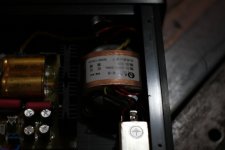
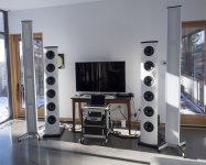
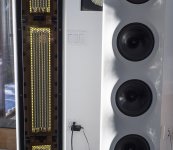
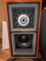
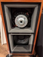
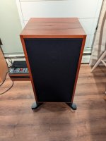
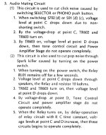
Hi guys, I need some help in designing a crossover for this line array speaker, we bought 8pcs of these speakers from Alibaba, and it turned out they do know how to copy drivers but the crossover was a joke. Ok all together for someone who doesnt know nothing about audio it probably would be okay, but not for us.
So the setup is:
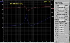
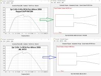
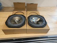
2*10 inch (4ohm each)
B&C Speakers
1*8 inch(16ohm)
B&C Speakers
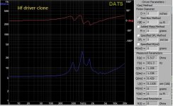
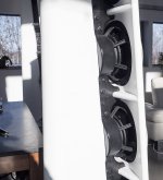
2*3inch hf drivers (8ohm each)
B&C Speakers
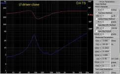
Keep in mind our speakers are not the original bc speakers these are quite good clones as you will be able to see from the impedance measurements.
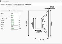
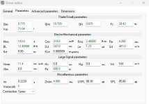
Also it is a speculation, I am by no means sure that these would be in the orginal v8s. Based on coil size throat size, and the looks of the drivers we were able to sort of identify them.
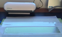
We had a friend come over to measure the drivers with dats V3, unfortunately he really had no ideea how to use the dats and I certainly never used it so these measurements could be a little off. I think at the time he shorted the terminals of the dats to compensate for its resistance but i am not sure about other fine tuneing procedures we should have done before measurements. These were my first ever impedance measurements of any sort
😎
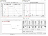
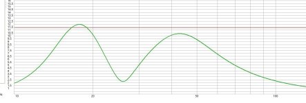
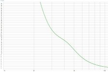
So based on the impedance curve, the 10 inch and the 8 icnh drivers are at least similar to the bc speakers ones but the hf drivers impedance curve has an extra peak compared to the impedance curve found on the bcspeakers website.
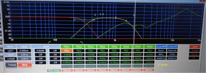
My original problem is that i know these speakers could sound a lot lot better, but my problem is that pretty much over 10khz the hf drivers wont really sound, i disconnected the passive crossover network and used my xilica DSP(at the time i did not have the impedance measurements yet) to try and make a crossover based on Mr. AllenB s passive xover tutorial.
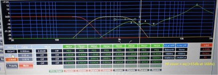
The conclusion was that i have got to a point where the speaker really had a clean crystal clear tone which was appealing to my ears it really did sound AMAZING. I will upload the pic of the xilica xover i made. The real problem afterall is that i needed to add an eq of +9dB pretty much over 7khz to get the drivers to sound good. When making this crossover on the xilica I had Smaart to wiev the phase and the magnitude of the speaker. I think i used ECM8000 mic for these tests. In the effort of making the response of the speaker as close to flat as possible also keeping the drivers in their optimal operating range.
After this i thought of making that exact same xover i made on the xilica but making it a passive xover, sadly i soon realised higher order filters wont really work for me bacause of many factors(first problem is size, after that comes price and power handling,etc). I soon realised this is not gonna work.
My next approach was to design a filter that wont cost a fortune, that will handle power (afterall we have been pushing these speakers around 2-3kw at the end of the day) and will make the drivers operate at optimal conditions, reusing as many parts off the original passive network as possible. My final choice became 2nd order bw for the 10s, and 3rd order for the bandpass drivers upper cutoff, as well as the hf drivers(to eliminate all the peaks and dips i had measured with smaart.
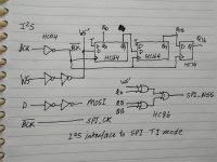
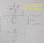
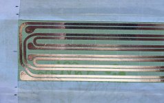
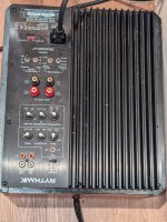
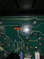
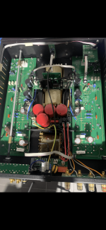
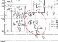
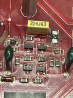
At this moment i quickly drew a schematic off the xover that came with the drivers and my judgement told me it was horrible, so i decided i wont simply play with the existing xover (since clearly it was a 2 way xover and it was made in to a 3way xover later on) but i will let decide everyone about this circuit(pic uploaded). In the original setup the speakers had their 10s in series for a total impedance of 8 ohms, the mid is 16 ohm, and the hf driveres were put in paralell for a total impedance of 4 ohms.
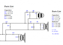
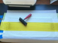
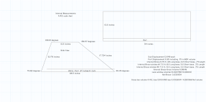
So after countless hours of reading i designed the actual xover with impedance flattening and all, and based on the impedance measurements and the graphs of the bc speakers i came to a conclusion that the ideal frequencies to cross at would be 500hz and 2100hz(i used a simple 2 way xover calculator but tried to estimate impedances as best as i could, calculating in the hf drivers impedance flattening resistor, wireing the two 10s in series for 8ohm, also the hf driveres are in series to achieve 16ohm, the midrange driver is 16ohm aswell) but when making the actual prototype i realised i needed a lot of help with the inductors.
There are a couple of values i cannot really achieve without a laminated or other type of core, but i do not know how to make sure i do not get around the saturation point of the core. I mean i have an lcr and i have a laminated core, i could get down and make my inductor with magnat wire, but then again how do i know what gauge of wire to use to handle these currents. Ballparking it isnt gonna cut it for me because i cant afford to disassemble these speakers every day to see if it works, could anyone point me in the right direction please? What is the procedure for sizing the GA of the inductors magnatwire?
In the meantime i did a quick google search to see if there are any other xovers readily available for the V8 since a lot of companies copy these speakers in china with minor differences between eachother, i can sort of imagine some dudes copying the cabinet, other dudes copying the speakers and other dudes copying xovers etc other stuff, and finally another dude buys the pieces and pieces it together. At the end of the day the company that sells these speakers actually has no clue what they do to the point they couldnt show a graph off the speakers output when we asked. Not a single graph, nothing.
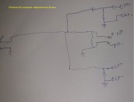
After some googling i have found an xover that is claimingly being made for the v8, and it has the crossover frequencies of 450hz/2100hz
so i took the time and reverse engineered it based on the pics i have found at the sellers page(not knowing the values of the components), but i was curious to see the order of the filters etc. to compare it to my circuit. Keep in mind i did not draw the ptc in this scematic diagram.
So the big question is should i go first and second order or should i go second and third order? Also how do i take in consideration the power handling of the speakers when designing the xover? I found out with the capacitors i can calculate their max voltage easily but with inductors?
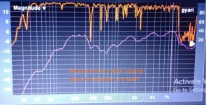
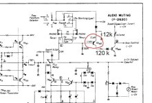
I also uploaded a pic in smaart showing the graph of the speaker phase and magnitude, with the crossover it came with, there are no eqs nothing applied it is just fed with pink noise.
Thank you for reading my mess and thank you all for your replies!


