GZ34 occasional runaway voltage

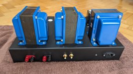
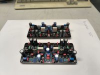
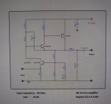
Hi, I'm just completing my first build, amp based on F2a tube. With much help reading the forums, so thanks.
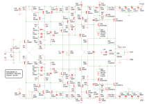
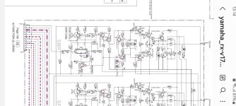
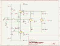
It's based on Moxtone Siemox online schematic but I've modified to monoblocks that use GZ34 rectified power supplies.
Testing had been going fine, and get B+ around where I expect, surge to 425 then settling around 380. But on a couple of occasions, on one amplifier, turning on from cold, the B+ seems to have continued to surge to 600 or more.
The first time I hit the kill switch after maybe seeing over 1000v, may have been negative (it was all quite quick, I may be mistaken). I added 1n4007 diodes and increased my first resistor to 97ohm from 47 ohm, and even swapped in a nos gz34. Seemed fine for first few times. Then one time I saw the multimeter hit around 600v and stay there. This was a different multimeter and I think its limited to 600v. I tried again later and all was fine.
I have the load wired in with 8ohm load, and valves seems to be drawing 130mA. When it starts up fine I have checked square wave on an oscilloscope and seems good.
Any ideas what may be happening here? Did I just imagine it?
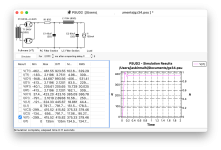
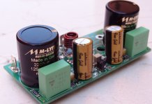
CLC using 45uF first cap. Attached PSUD pic. (Plus bleed resistor 1M not shown).
Thanks for any thoughts.

Attachments

  • GZ34.png
    GZ34.png
    243.3 KB · Views: 89

ALSA and JACKD S/PDIF output

I have some motherboardS with either optical or coaxial spdif output that I would like to use as the only output but all of them have this problem with alsa :
although aplay -l show the spdif subdevice I can not choose it it does not appear in alsamixer or qjackctl devices available.
can someone help me a bit with this alsa simple problem (I can remove jackd if that helps) ?

For Sale UK TubeLab Simple SE amplifier KT88 6L6GC 6P3S-E

TubeLab Simple SE amplifier KT88 6L6GC 6P3S-E

TubeLab Simple SE amplifier that has been stored for the last six years, I need the space.
Didn't think I would ever sell this, my most successful DIY effort.
While I make no claims of safety/ warranty, Always do your own due diligence.
I checked over the amp and re soldered and cleaned some of the connections, then powered up without issue. I spent a night listening, the amp works without any hum or noises.
See photos for condition and moody long exposure glow.
Edcor XPWR059 wired for 240v, currently $179.
Edcor CXSE25-8-5K Output transformers, Currently $154 each,
Hammond 193H choke
Hammond enclosure, with Fender style Jewel LED and power switch.
80uF Motor run cap.
Thermistor for soft start, Auricaps, Nichicon caps.

Comes with one pair of 6P3S-E output valves
One pair of 6l6gc output valves
One 5U3C rectifier
One JJ ECC81 input valve.
£300

Happy to demonstrate.
Collection from Southeast London SE4, not willing to post due to weight and fragile nature.
PXL_20240612_161911697.jpg


Shuguang KT88-98 Matched Pair
Matched pair, never used. In original packaging. With measurement stickers.
£50 including UK postage.
PXL_20240612_152513166.jpg

Attachments

  • PXL_20240612_204424820.jpg
    PXL_20240612_204424820.jpg
    116.4 KB · Views: 69
  • PXL_20240612_161852412.jpg
    PXL_20240612_161852412.jpg
    260 KB · Views: 61
  • PXL_20240612_162109827.jpg
    PXL_20240612_162109827.jpg
    536.3 KB · Views: 68
  • PXL_20240612_154338378.jpg
    PXL_20240612_154338378.jpg
    411.9 KB · Views: 79
  • PXL_20240612_151035662.jpg
    PXL_20240612_151035662.jpg
    436.4 KB · Views: 92
  • PXL_20240612_151038718.jpg
    PXL_20240612_151038718.jpg
    435.5 KB · Views: 92
  • PXL_20240612_151038718.jpg
    PXL_20240612_151038718.jpg
    435.5 KB · Views: 93
  • PXL_20240612_204254149.jpg
    PXL_20240612_204254149.jpg
    155.2 KB · Views: 85
  • PXL_20240612_151332843.jpg
    PXL_20240612_151332843.jpg
    404.9 KB · Views: 75
  • PXL_20240612_163109841.jpg
    PXL_20240612_163109841.jpg
    409.2 KB · Views: 69

Rotel RB985 Noise floor problem?

I recently got a used RB985 on the cheap and trying to make it perform. I have an issue that I have not come across before and am hoping for some ideas or pointers what might be going on.

The odd thing is that the noise changes with what signal cable I use and with the cable disconnected it's "silent".


Adding a pic of how it looks on REW and a Focusrite G3. Red is the signal cable disconnected and green with it connected to the preamp muted and I have obviously tested with other amps, in this case the Rotel RB 980 and with that there is no difference with the cable disconnected or not.

RB985 Noisefloor.jpg

SWTPC Universal Tiger Inconsistencies

I rebuilt a mono UT for analysis in this thread below and found numerous ways to induce
oscillations:
SWTPC Universal Tiger Rebuild For Analysis

I began to make minor changes such as moving grounds around and thought that it
would be good to have another one that could be left without changes as a reference
since I have 3 of the mono block UTs. The second one did not oscillate in any of the
ways that the first one did.
Started by looking for visual differences:
1. First (UTM#1) is on an aluminum chassis, second one is on steel (UTM#2).
2. Capacitor brands are different
3. UTM#2 has a lot of corrosion, probably from sitting in a damp environment
for many years. I should probably clean the grounds.
4. UTM#2 has nearly every solder joint with about twice as much solder as there should be.
a joint could be cold, but who knows?

Obviously semiconductors have wide variations in parameters and I don't have a curve
tracer to test each one. I suppose the VAS is a likely suspect since one with more internal
capacitance might improve stability acting as a Cdom cap.
I know for sure that many of these oscillated from past experience, yet a few builders
report no problems at all.

I wanted to keep the speculation on this issue in another thread just for clarity - so here it is.

I suppose that I should try UTM#3 to get another data point.

Final 0.4 mkIII Electrostatic Issues

Final 0.4 MkIII Electrostatics​

Hi to all.
I recently purchased a pair of these speakers. With the speakers came two different 12v adapters. One was a 0.5va and one was a 1.54va.
Upon listening i found that the 0.5 was not powering the panel ( I did alternate supply to each speaker to confirm it was supply problem and not speaker)
My first port of call was to contact Final where i was informed the 0.5va - 6watts according to Mr Ohms - is enough to power the speakers and that as it wasn't, the problem must be the internal transformer. Now... as the 1.54va seemed to power the panel I thought until I get time to get the speakers looked at and the internal boards tested I would buy another 1.54va supply just so as i could get a good idea of what the speakers sound like. Not able to find a 1.54va I settled for two 2va adapters so at least the supply was matched.
This itself presented another problem as for some reason I cannot seem to hear either panel now!! When i sit back and play some tunes that I'm familiar with everything sounds as it should. The soundstage is huge, the trebles are there and it does sound very good but upon standing in front of the panel I'm not hearing anything!! Am I missing something?
Note: I am using a modded Cyrus 2 + PSX

Current feedback: impedance and phase issue

The difference between current feedback and voltage feedback for audio amplifiers is a non issue. Voltage feedback amplifiers for audio applications are superior to their current feedback peers.

Given a set C of current feedback amplifiers and a set V of voltage feedback amplifiers, there exists an amplifier V(x) that has higher bandwidth than an amplifier C(z)

How much of a phase difference? One or two be junctions or gs junctions. Yes these can make a difference to the stability of an amplifier.

There is an advantage of having a symmetrical design with an LTP and that is LTP error cancellation, especially if the LTP is matched and essentially in the same package. Better still if the LTP package is paralleled.

Current feedback is a term coined from the nature of the low impedance input, nothing more other than the phase and nothing less. Add an active device and it becomes a high impedance input and now we call it voltage feedback

WTB Mylar

Apologies if I should be asking this in the Swap Meet section instead of here but figured I may get more responses here; please move the thread if need be.

Anyway I am looking into from where I can buy some Mylar and other ESL supplies. Plain and metalized in the popular or wider widths and thinknesses suitable for building a DIY ESL. So far I've found the following through ggogle and searches on here. If you can think of any others please reply. If you have your own surplus to sell feel free to reply or PM. Also interested to know about any postive/negative buying experiences if the rules here allow ( can't remember ever reading the rules! 🙂

IanCanada HDMIpi MkII with piCorePlayer

I purchased an IanCanada HdmiPi some time back, and finally decided to try to get it running. I've got a Pi 4B running the latest piCorePlayer. At this point I'm not running a separate power supply or Fifo in the system, but I am using a DIY linear supply to power the Pi.

According to the docs I've found, I don't need a special driver. However, I'm unsure which Output Device to choose for the hat to transmit I²S via its own HDMI port. I notice that this unit has additional HDMI options beyond "HDMI Audio". I've tried all of those, with variety of corresponding "Output Settings" for each. However, none seems to transmit I²S to my Wandla DAC.

Any words of wisdom?

For Sale Geoffw1's Mooly MOSFET Slim SMD boards

Three pairs of @geoffw1 slimline SMD boards for the @Mooly MOSFET amp.

2oz copper. I have spares because, among a bunch of other orders, I got curious about the charge for 10 boards, changed the QTY then forgot to put it back once my curiosity was satisfied. Imagine my surprise when I opened the JLC PCB box.

No charge for the boards. I'd rather takers made a donation to a hospice charity of their choice. Amount is up to you, whatever you think the boards are worth. I'll cover the postage for UK and EU.

20240716_132615.jpg

For Sale Shunt Regulator PSU boards

SOLD
Two Shunt Regulator Boards for sale.
Made 5 boards, selling this two spare boards.
Works very well and sound very nice.
Current is now set at 150mA. This setting can be changed with one resistor on each rail.
And of course you need to be mindful of the thermal increase if you decide to increase the total current.
Output voltage can be adjusted using a single trimmer. Currently set to +/-10Vdc.

Designed by Dadod :
https://www.diyaudio.com/community/threads/shunt-regulator-15v.286425/

These boards I have is smd version (well, maybe 90% smd parts), schematics and gerbers are here :
https://www.diyaudio.com/community/threads/shunt-regulator-15v.286425/page-8#post-7503893

Both boards total of $88 USD, shipping cost is included (registered + tracking ).
Paypal FF only please.

Mackie HR824 MK2 low frequency distortion

I recently bought a used pair of Mackie HR824 MK2 active speakers. After listening to them for a while I noticed what sounds like low level distortion while music is playing, but the distortion peaks don't seem to be following the peaks of the music. I used a tone generator in my DAW software and isolated the distortion to 60 hz and below, and it sounds to be coming from both the woofer and tweeter. Wondering if the distortion is from a driver or the plate amp I swapped the plate amps on the speakers, and the distortion follows one amp. I also noticed that the auto power on feature isn't working on that amp, which may be related (or maybe a separate issue). Any ideas on what could be the cause of the distortion? Maybe a bad electrolytic cap? The power supply filter caps are Jianghai brand, and the other electrolytics are JH brand. I know little about electronics, and help on what to look for is appreciated. If it's a simple fix I would like to keep the speakers, else they can be returned.

Owner's manual with block diagram on page 18
https://mackie.com/img/file_resources/HR824mk2_OM.pdf

Schematic (download link at bottom right)
https://www.audioservicemanuals.com/m/mackie/mackie-hr824/4208092-mackie-hr824-mkii-schematics

For Sale MicroAudio (Cresnet) Cobra S1 SMPS

I am looking to make some room as I likely won't get around to using this awesome power supply with a little one on the way... I suspect my DIY builds will be on hiatus for a little while lol.

This unit has not been used, yet. It was built and tested about a year ago. Asking for $300 shipped (I'll cover shipping within the USA). PM if you live outside the USA and we can figure something out. This unit would otherwise run you $500 with shipping.

This SMPS was spec'd accordingly:
  • Output voltage = +/-32.5VDC @ 4.2A
  • AUX Voltage (Regulated): +-18 VDC
  • Driver voltage: +12 VDC
  • Primary Capacitors: Nichicon 390uF
  • Voltage regulators for (+-AUX) : LM78XX
  • Voltage regulator for (VDR): LM78XX
  • Standby power supply voltage: +12VDC (3W)
  • Secondary Capacitors: Mundorf MLGO 33,000 uF (132,000uF total; additional cost)
This SMPS can deliver up to 15A peak, which should cover most projects. >:]

As you can see from the photos, I've included the necessary adapters as well as a cooling fan which you can mount. There's a fan jumper for either fan always on, or fan on with SMPS.

You can use the included adapter board to split the rails for two channels.

If you look around this site, you'll find high praise for Cresnet's SMPS, and especially the Cobra's performance.

If you're not familiar with this product, I advise you take a look at the product page here.

PXL_20230507_004818322.jpgPXL_20230507_004834006.jpgPXL_20230507_005003738.jpg

PEECEEBEE V5 GB

Working. Bias 150mA, Offset 5mV. Power supply 40V DC. Sound perfect. Thanks Shan. Price 150€


Specifications:
Power (+/-50V PSU, 0.1% THD) - 140Watt into 8R, 250Watt into 4R
Frequency response (simulated) - ~2Hz to ~700KHz (-3dB)
Slew Rate - 60V/uS
Offset variation - +/-10mV
SNR - 112dB+
AC gain - x28 (28.9dB)
DC gain - Unity
Input level for 250W into 4R - 1.2VRMS (~3.4V P-P)

Attachments

  • IMG_20240705_160542.jpg
    IMG_20240705_160542.jpg
    134 KB · Views: 146
  • V5-REV1-SETUP.pdf
    V5-REV1-SETUP.pdf
    62.1 KB · Views: 42
  • SCHEMATIC(1).png
    SCHEMATIC(1).png
    56.3 KB · Views: 146
  • Like
Reactions: yoaudio

Design philosophies and variations in amplifiers

After reading Douglas Self's book on amplifiers, I've understood there's a lot of variation and design philosophies out there.
Using the schematic from my own Yamaha AVR, there are a few details I would like to understand. I can't seem to get decent results on my own searches on Google and here, and don't possess the skills to break down and analyse all sorts of circuits yet.

(1) Is there a name or explanation for the compensation scheme in this amp?
There seems to be more scattered caps plus the RC-network R304/C294, witch cap value seems very high compared to the usual Miller cap value.

(2) Q257 seems kinda like half a current mirror, or the 3rd transistor in a Wilson mirror, but without the mirror part. I haven't been able to find out exactly what is going on. I could probably do some simulations, but alas, I'm not there yet.

Attachments

  • Screenshot_20240122_131421_Samsung Notes.jpg
    Screenshot_20240122_131421_Samsung Notes.jpg
    230.5 KB · Views: 170
  • Like
Reactions: hbtaudio

Are Class D (TPA) amps really that much better than Class A/B amps?

In 2021 I bought a $35 TPA3116 2.1 amp for portable music. I was actually quite impressed with it. It really made a set of SLS (Superior Listening System) ribbon bookshelf speakers sparkle. I used the trio for camping for a few years and to shut up those obnoxious shrill pill box speakers that friends would bring camping.

I decided to build a passive 6" sub with a pair of 7" radiators and the cheap TPA3116 broke down. So I bought a WONDOM AA-JA33286 JAB5 4x100 Watt Class D (i.e. Dayton Audio KABD-4100 4 x 100W) with DAU1701 DSP and dual TDA7498E amp chips for 2 x 100w + 200w subwoofer. I am very impressed! The SLS speakers aren't noticeably cleaner (still REALLY impressive though) but my DIY passive sub really came to life! So it is time to integrate the amp board, sub, radiators, 12x18650 batteries (29vdc), and 36v 10A ps into a boombox format with mounts for attaching the SLS speakers where they are easily removable for better imaging. After a week with the separate pieces in my shop (I am a woodworker) I REALLY grew fond of the setup while building the box. Now that it is time to wire everything into the box I am really missing having music in the shop.

So I pulled out my ancient Yamaha RX-V2090 receiver. MAN IT SOUUNDS LIKE CRAP!!!! My old RX-V890 was no better. My current Yamaha Aventage 2010 is no better than the old Yamahas either. I can't believe how bad the old Class A/B amps are in comparison to a Class D! I had a Threshold 400A amp, Anthem pre and Magnepan II speakers when I was using the Yamaha receivers for HT and I knew the Threshold Class A 400a amp blew the Yamaha away for clarity, detail, and imaging but these Class-D amps are rivaling my "memory" of my "hi end" music system of my youth. Unfortunately my 400a has a dead channel and the Magnapans need new mylar so I can't compare side by side.

Are Class D amps really that much better than solid old Mid-Fi Class A/B amps? Do they push into the realm of classic Class A amps?

My Magnepans haven't seen the light of day since I moved to my current house 20+ years ago and I still don't have room for them. What I am wondering is if my Threshold 400a is worth rebuilding for use with good quality bookshelf speakers in the bedroom?

I am also seriously considering dissecting the 2090 for the power supply board and transformer to experiment with other Class D boards (or Chinese Class A amp boards - KSA-50). Can anyone think of any reason I shouldn't? My 2090 really feels like it is just trash now.

Wondom 4x100w + dsp: https://store.sure-electronics.com/product/756
Much cheaper then the same board from Parts Express: https://www.parts-express.com/Dayto...uetooth-Amp-Board-with-DSP-325-434?quantity=1
  • Like
Reactions: cumbb

Any feedback? Help with my current install on my 06 Daytona?

I have 06 Daytona upgraded system. I have 2 scar audio super tweeters in dash, 2 NVX 6X9 woofers in doors , 2 6X9 5 way pioneers in rear deck. And for subs i have 2 Alpine Type R 12 (grey ones). Dash,door, and deck speakers are amped by NVX VAD4 400watt mini amp. Woofers are amped by Older memphis 1000 watt mono block class D . My issue is im having feedback through my subs. N its pure bass. Been a couple diiferent things from pop when shouting car off, to thumping bass after tuning, and now when rolling Windows up its like a pure bass line. Any ideas? Is it grounding issues or is my amp goin out? Pls help its my fiance car n she loves her stereo system.

Rewire SpeakOn to RCA?

I admit I am rather clueless when it comes to SpeakOn cables (and I have consumer level equipment.. sadly), but I inherited an under-floor run of cable where the previous owner went all out and ran SpeakOn cables to all points of the setup. None of my devices have SpeakOn, though (I am lame and have regular coax cables), so I am reflecting on what I should do. I am not certain I can re-run the coax wires under the floor, so I am looking to see if there's anything I can do with the SpeakOn wires.

If my eyes serve me right, I have the 4-wire SpeakOns. Is it feasible (besides being anathema, I suppose) to undo the connector and pillage 2x2 wires to build my own RCA connectors? The other problem also is that the previous owner had his amp in a different place, so the cables converge there - where I want my amp right now, there are only 2 SpeakOn cables going there, so that doesn't help me very much.

Any thoughts welcome, thanks very much!

balanced line receiver and headphone amp modules

Greetings,

I’m interested in building a headphone amplifier in a rack-mount box. The architecture would look like this:
1) A multipole switch to select one stereo pair of balanced inputs from among 3-4 choices,
2) Two balanced line receivers for the selected stereo pair,
3) A stereo volume control
4) a stereo headphone amplifier

I need to simplify the construction process, so I’d be interested in finding pre-built modules for the line receivers and power amplifiers.
I’ll look for a power supply module as well, I assume with +/- supplies.

The purpose of my post is to seek advice and/or recommendations for the components:

I’ve already got a great 4-pole multi-throw rotary switch for the selector.

I recall buying some balanced line receiver modules using THAT line receivers, but the modules are now discontinued. Any suggestions?

I see a variety of headphone amplifier modules. I’m not sure that paralleled 5534’s would meet current demands in all cases. And I need to make sure that I can drive stereo headphones that share a common ground terminal. I need to drive low-impedance as well as high-impedance headphones to a moderately high sound level (but not hearing damage levels!)

I managed to find a headphone amplifier on a board with balanced inputs, but I need to add a volume control. Putting the volume control ahead of the board would require a balanced attenuator, for which it is expensive to maintain CMRR. Affecting the gain of the amplifier with a modification (i.e., vary the gain setting resistors) could degrade CMRR and perhaps degrade the stability of the amplifier. Besides, doing two balanced channels would require a 4-gang pot.

Here is that item: https://www.mouser.com/ProductDetai...9TiaZ2VIN468UPyuaLWSlrPcRqonNVOUaAsX6EALw_wcB

Maybe I could use the board above and add a good balanced receiver and volume control in front of it? Or maybe consider a different choice for the headphone amp?

Tom

My class T amp has no sound , should I bin it ?

As I said in another post I bought this amp as none working and blowing fuses , once I opened it up there was one fuse missing and the led ( power indicator) wires were lose and potentially touching the chassis. I reconnected the led , replaced all the fuses including the one that allegedly kept blowing at the iec power input socket.
Could it be the chip that’s dead ? There is a little green led near the chip that doesn’t light up .
I can hear a relay clicking after a few seconds of powering on but no sound into the speakers ( 000.3mv at the terminals )
Should I just forget it and keep the case etc ?


IMG_7132.jpeg

Technics SP-10 Mk.II braking system overhaul

Hi folks.

Hope somebody might be able to help with the following.

After quite a long search, I've managed to find a complete braking system for an SP-10 Mk.II on Ebay, with the added bonus of a (supposedly) working strobe light too. £70 so rather an extreme price, but it's all advertised as working, and I guess these spares are pretty rare now. It'll be nice to finally have a 'complete' deck at last, as my SP-10 had the braking system removed by its last owner.

Unfortunately the braking solenoid needs some work by the looks of it. It needs cleaning, a re-lube, and the rubber end-stop washer (part 14-4 in the service manual) isn't there.

I assume I can use a bog standard rubber washer of appropriate size there. Does anybody know the thickness of this item though, and the circumference? Also I haven't a clue what kind of grease I should use to re-lube the solenoid - any advice here would be much appreciated indeed.

Cheers,

- John

Aiwa CDC-MP32 Headunit Unresponsive

Hi, got this older flip headunit that isn't fully working that I'm not really sure what the problem is.
Display turns on and lights up, however no text or anything appears, all buttons are unresponsive (besides reset button) and the display does not flip as it should (second image).
Reset button moves the flip mechanism gears very little that you can hear it and see it (only after looking inside) 1-2 seconds after pressing. The display will not move when this happens (besides very slightly that it is easy to miss as if it tries to move).
Tried putting standard 12v to it, and the recommended 14.4v, same result.
When it turns on you can hear it start to read a CD that is inside of the CD slot then stops.

Attachments

  • IMG_7582.jpg
    IMG_7582.jpg
    306 KB · Views: 161
  • h570CDCMP32-o.jpeg
    h570CDCMP32-o.jpeg
    19.1 KB · Views: 124

Pioneer D9601 repair

Hi everyone,
I’m trying to repair Pioneer D9601 mono amp, someone tried to repair it before me, but they just couldn’t get it to work.
I measured resistance of 4227 output transistors, gate and source is 4.74 for low side and other resistors show 4.64, some resistors were clearly changed before, but they seem to be working. All of them are charging as far as I checked no short.
Up on opening the case, I noticed one resistor is missing and was changed to two resistors and one capacitor is missing as well. I tried to find values of resistor and capacitor, but no luck.
I will attach some pictures, perhaps someone knows what resistor and capacitor I should use.
The amp turns on, but goes to protection mode, red led lights up.
Any help appreciated, thanks.

Attachments

  • IMG_1720.jpeg
    IMG_1720.jpeg
    170.6 KB · Views: 92
  • IMG_1702.jpeg
    IMG_1702.jpeg
    548.6 KB · Views: 87

The correct installation of Snap-Fit Aluminum Electrolytic Capacitors?

I was putting together a BOM recently and looking at KEMET snap-fit/press-fit capacitors and was shocked (not literally) to read in the attached datasheet that this type of capacitor is not meant to be soldered in. So, I've been doing it 'wrong' for years. I'd always soldered them in, assuming the snap-fit was just to hold the capacitor secure during soldering.

The thing is, I've never seen a snap-fit capacitor just being pressed in without soldering, not in diy or commercial products. Has anyone ever seen this in a commercial product or use them the way they're intended in diy?

Attachments

Crescendo 140W VS 250W

Hi All...
I do hope it's in the right thread I'm posting

The Crescendo with 4 output transistors VS Crescendo with 8 output transistors respectfully 140w VS 250w, how is the difference possible ?

Would som one help me figure out the calculation on the output on Crescendo 140W@8Ω and The 250W@8Ω
I struggle to see how it is calculated.

Both amps has a power supply at ±75Vdc how can there be a difference when the load is 8Ω.
I am well aware that the 250W has 8 output transistors compared with the 140W that has 4 output transistors

The biggest difference is the R31 1Ω parallel with Coil @ 2µH in the 140W version witch is not present in the 250W version.

Both amps has losses in the drain resistor @ 0.22Ω however the losses in the 250w version is almost not existent since the resistor is in parallel so 2x 4//0.22 in parallel compared to 2x 2//0.22Ω.
However this doesn't justifies the huge difference in the output.

In reality both amps are looking in to the same load, no matter if it is in AC orr DC perspective
So the big question is why is one amp rated to 140 W and the other 250 W and both are measured in 8Ω ?

Best Regards Allan

Sometimes You Can't Put Off Something That Needs Doing Any Longer

I like to play the two jukeboxes I have in our summerhouse, when I'm working in the garden.

This is the younger of the two.
It dates from 1976. They were produced for hotel foyers and high-end bars, where "Silver Age" machines were considered to be out of place. The graphic is a reproduction of Monet's Sunlight Under the Poplars.
I've had it about fifteen years.

P1010209.JPG

This is the flyer produced to promote this model, seems so incongruous now.


1720543793038.jpeg


Over time, I've had a problem with the carousel motor, running slow, to the extent it would often activate the trip that protects the mechanical side.
I took it out and gave it a bit of a service a few years ago, but it was recently doing it more frequently. It meant that sometimes if the next selection was a couple of dozen records further away in the carousel than the last played, it would stop. There was a chance it might not "trip" and I'd eventually have a bigger problem.

So I "bit the bullet," and took it out last Thursday. This was no easy task. A question of removing three bolts.
Sounds easy, but it's a nightmare.
It would have been impossible without a set of spinners.

P1010218.JPG


There's no way you could get any sort of regular open-ended or ring spanner on the bolts.

To be able to see anything, the front had to come off. It's just two latches that secures it at the top.
I've added a 60w heater, which gets turned on during the cold months, as these machines, "don't like it cold or damp."


P1010210.JPG


P1010211.JPG


Then the small back panel.

P1010213.JPG

This is all you can see.

P1010212.JPG


It was a question of finding the bolts by "feel" and then getting a spinner on them. You have to do this, by lying full-length on the floor. Not too easy when you're 84.

These motors are exceptionally well-made. They had to be, as most jukeboxes in their time were working all day, every day.

P1010214.JPG


There was a lot of scoring on the armature. This happens if dirt gets between the brushes and the armature.

P1010215.JPG


I'd attempted to reduce this on a previous occasion, but it was difficult, so didn't do it that well.
But this time I used a tip given me by another jukebox enthusiast. I put it in my electric drill and then locked the drill in the vice on my bench. Then wrapped a strip of emery paper lengthways around half a pencil. Just a question of turning on the drill and holding the pencil against the armature. A few changes of paper and the job was done in a few minutes. Then I carefully ran the tip of a Stanley knife blade to scrape out a bit of the insulation between the segments, as these must not be proud of the rest of the armature.

I did connect it up and had it running to check it out before I started to put it back in.
Getting it back into the jukebox is a bigger nightmare, as you're doing it by feel. I put Blu-tac around the bolt and the head of the spinner to stop it falling off. I managed to wedge a Philips head screwdriver through one of the holes in the motor bracket and the jukebox chassis to line it up, So I could screw in the first two bolts.
Sounds easy, but it took me half an hour to get it back in.

Now in perfect working order.

If I'd called out one of the very few jukebox servicing companies, no way would they have wanted it to do it here. They'd want to take it back to their workshop and raise it off the ground to a working height. This would have cost "an arm and a leg."
It cost me 59p for a sheet of emery paper.

P1020123.JPG

Another C Audio SR606 fixed

This one is an early version with each both of the protection circuits used for each channel and the three relays for the soft start circuit. Bit of a mess this one (with plenty of other people been in it! 🙁 ) all the output MOSFETs test fine! 32 of them and original...I'm shocked. Someone previously tried to fix this with a driver board from a SR202. They actually wired the drive and feedback wires the wrong way round. So the drive was connected to ground. Cue shorted driver transistors, burnt resistors and vaporized tracks and probably other shorted semis. I had a spare driver card for this from a SR707. Changed to the correct feedback and protection resistors for an SR606 , did the three 27K resistor mod, increased the feedback DC feedback electrolytic cap to 820uf from the 100uf, changed the DC block caps before the gain pots to 220uF bi polar.

powered up on dimbulb, clicked out of protection. DC offset settled at 30-40mV. Bias at 500mV.

Plenty of bass! Sounds very good. Very little square wave tilt at 20Hz. 10Khz square wave has a very slight soft edge. No ringing/oscillations.

Then when I put my hand on the case, DC protect triggers and my RCD even tripped! Took me a little while to work it out. The case sides had a different ground potential to the back. There should be a washer sandwiched between the bolts at the back to keep a good ground for the whole case. The back panel was also not tight. I put in new washers, tightened up the back bolts and no DC trigger. Mains earth wire was also secure to back panel. and mains cable entering amp in good condition.

The three soft start relays are getting weak or need cleaning, When amp is on its side the amplifier fails to start.

The signal grounding is a bit different in these amps I always thought pin 1 of XLR input should be connected to chassis but its connected to screen which goes all the way through the circuit ground. I believe the CMR can be improved too with a change of resistors around the opamp. If i remove the screen cable from XLR pin 1 the DC offset goes up to around 120mV.

Anyway, it plays and sounds good.
IMG20240715190908.jpg

Attachments

  • IMG20240715135248.jpg
    IMG20240715135248.jpg
    399.8 KB · Views: 86
  • IMG20240712094954.jpg
    IMG20240712094954.jpg
    214.2 KB · Views: 69
  • IMG20240712094937.jpg
    IMG20240712094937.jpg
    291.1 KB · Views: 61

Phase Linear 400 Series 2: Meter Issue

I have a Phase Linear 400 Series II on my bench that has two LED's lit up on the right end of the meter when (and where) they shouldn't be. This is as soon as I power on the amp, no signal.

LED Board.jpg

What I've done so far:
  • Checked all electrolytics. One was open (C304).
  • Checked all resistors and diodes.
  • Exercised the trimmer, R306, applied a few drops of Faderlube, and reset it to match the other board.
  • Checked all transistors in circuit, comparing boards.
  • Checked everything, including the two UAA170's, with my curve tracer/octopus tester. No evidence of leakage, though the test voltage is lower than what would be seen when the amp is on.
  • Replaced the RC4558 (Z301).
  • Checked for cracked/cold solder joints.
I'm suspicious of the UAA170's, but should I be?

Apologies for the resolution of the schematic.

Display Schematic.jpg

Monster Amp

Okay ladies and gents, it's time to build a beast and I'd like your input!

Goals:

  • Class AB
  • Gain 22-28dB
  • Inputs XLR/RCA
  • Power Out per chan 4-8 Ohm 300-600W range
  • Power consumption NA
  • Type Mono
  • AC 110 USA

Input friendly to a wide variaty or pres including valves.

I would need to split the output devices, so I can use both heatsinks on each mono, (left and right side of case)

This will drive many speakers, but ill be hooked up to a pair of Tekton MOABs 4 Ohm 900W when I want to raise the roof. These are very efficient and need not be driven, by this beast, I know this.

As far as THD goes I'm not married numbers, but I don't disregard either. I don't like bright or forward amps as my ears are sensitive to higher freqs. The F5 is a great amp, but forward, to my ears.

There will be soft start boards and SS speaker protection on this one.

The footprint of each case will be 430*200*411mm

Music Classic Rock, Blues, Jazz, pretty mh everything, but this one is going to be mostly for ROCK!


Some thoughts: I have been reading threads for possible DIY amps here, but at times, there are several hundred pages and many changes along the way making it daunting to figure out which direction to go.

If possible, I would like a solid BOM (with as few nonstocked or obselete part as possible) and boards or Gerbers for them.

This amp will get built, I'm not one to ask for something and not follow though. The intent is to make this one the very best I can. I have found some very nice cases and I want this to be the best work yet.

Thanks, in advance, for your input.

JT

What else than an Apple Mac Pro M3 do I need to replace DBX Driverack PA2

Basically I want to do all sound processing in the Mac and have a "box" with stereo low/mid/high outputs that I connect to my amps. Besides the "box" what software do I need and are these boxes available?

What I found so far:
... and ChatGPT:
  1. External Audio Interface: The interface should have multiple outputs (at least 6 if you need stereo low/mid/high outputs) and high-quality digital-to-analog converters (DACs).
  2. Digital Audio Workstation (DAW): Logic Pro X, Ableton Live etc
  3. EQ and Crossover: FabFilter Pro-Q 3, Blue Cat’s MB-7 Mixer
  4. Compression and Limiting: iZotope Ozone
  5. Audio Routing Software: Loopback (for complex audio routing setups), Audio Hijack (capturing and routing audio)
  6. Real-Time Analysis and Optimization: Smaart v8 (sound system measurement and optimization)

LEAP replacement?

Haven't designed in many years, I 1st bought LEAP in 1995! I'm a huge fan boy, it's an amazing program but very difficult to use these days since Chris passed and its acient tech. I cannot seem to find a replacement, I found some nice measurement systems to replace LMS but not a proper system optimizer, any recommendations??

Thanks

Geoffrey Dillon

Costco Chicken Fiasco - It's in the bag

One of the best deals at Costco is the cooked chicken for only $4.99. We have been buying them on a regular basis for years. But now they have changed the container from a hard plastic box to a flexible bag. The result is A BIG MESS, and we have stopped buying them.

With the previous box you can remove the top, cut up the chicken while leaving it on the base, and then replace the top for storing any leftovers. It was simple, clean, and easy.

With the new packaging, however, you have to completely remove the greasy chicken from the bag, find something to cut it up on, find something else to store the leftovers in, and then clean the greasy board you used to cut it up. Its's a huge mess and not worth the time and grease to do it anymore.

There are lots of complaints circulating about it, and some people saying that the previous plastic boxes were recyclable in their trash whereas the new bags are not.

Hello all

So, my name is Adrian. I do all types of DIY projects, but my main hobby is amplifier repairing, modifying, and restoring. I do the same with speakers. I don't really join forums because I don't have much free time. I also have a YouTube channel with the same nickname, although I haven't posted in a while. But I'm happy to join this forum because I see some interesting people here.

Will I damage my tweeters by this action?

I’ve read somewhere long time ago about crossover point selection trick that one could make a steeper acoustical slope by applying an electrical slope combining with a natural roll-off of the driver. For example, a conventional dome tweeter could be considered its low-frequency loading as a closed box system since it has been sealed on the back. As a result, the tweeter would have a natural roll-off at 12dB/octave rate. Once we apply a 12dB/octave electrical filter to it, the final acoustical response should have going to be a 24dB/octave slope by implication.

First of all, is it true?

Then, by performing that, is there a risk for damaging the tweeters, because the selected crossover point would be located at quite low and close to the Fs of the tweeters?

Moreover, since the x-over point is near Fs, will it introduce a large distortion to the speakers?

Finally, would the principle still be valid for the dome midranges, as their constructions are identical, except for the size?

Interblocck cables MiSHKiN

Hi all. After a long creative break, I want to offer you my new products, with completely changed architecture and materials.

1. New!!!
Appeared thanks to some discoveries in the design of interconnect cables. Maximum openness, relief of lines and information base, excellent vocal range. The location of sound sources is guessed with an accuracy of up to 5 cm. The sound field is higher than 3 m. Moreover, sounds are heard in front of the speakers, at a distance of about 2 meters, which was not the case in my experience before. The conveyance of emotions is at a good level.
The leader in transparency (of varying order) and tonal balance among many of my projects.

$370 with standard RCA.


2. Version with single core made of ultra-pure oxygen-free copper. $450


I will make a cable with any key while maintaining transparency.
At the moment there are 2+ types of tonality: bright and balanced. This way you can tune your equipment for tonal balance.
I'm sending you to a test audition with a cash deposit.

The design of the cables is different from most sold ones.
All conductors in the products have no or minimal insulation, and its effect is minimized to increase sound transmission. Since the speed of propagation of the electric field in air is the highest. Conductors without insulation are coated with a special anti-corrosion compound that does not affect the sound. They have polishing and special surface cleaning.

The cables have been tested using precision equipment. And they received high praise.
I will send the video upon request.

You may think it's all over-the-top, luxurious, and far-fetched, but the fact is that your brain won't accept old patch cables that cost less than $4,000.
I would like to convey my emotions to you, but this is unlikely to happen until you hear for yourself.

5 Unpatented or Implicit Design Principles!!! Special grades of copper, selected as a result of numerous auditions!!!

WELLKAM, if you are tired of changing equipment in search of a joyful sound...

The price will no longer be reduced because I have reached my personal ideal!!!

The price includes a club “LIFETIME” guarantee!!!
DISCOUNT (up to 80%) for upgrading the cable to the next version. What happens regularly!!! (I find this interesting in connection with the indirect action).

Attention!!!
The cables do not produce sibilance and do not distort the sound!!! Ultra transparent cables only reveal the shortcomings of the system. Therefore, they are designed for high-quality playback systems. This is their main difference from consumer products (and sometimes famous brands that ignore the manufacturing principles I use), which mask these shortcomings due to high capacity and insufficient purity of the material.
If the system has a voltage stabilizer with a sine restoration function, the effect will be double.
m.

I provide free samples to audio stores and retailers. Any real assistance with the sale of products will be paid for.

I apologize for the inaccuracies in translation. Google Translator helps me out, but sometimes it wants to show how smart it is)))

Attachments

  • 1718849480304.jpeg
    1718849480304.jpeg
    616.9 KB · Views: 97
  • 1718849480256.jpg
    1718849480256.jpg
    451 KB · Views: 81
  • 1718849480291.jpeg
    1718849480291.jpeg
    246.9 KB · Views: 71
  • 1718849480317.jpg
    1718849480317.jpg
    108.2 KB · Views: 68
  • XLR..jpg
    XLR..jpg
    223 KB · Views: 30

Digital Twin Loudspeaker Simulation

Hi Everyone,

I've been tinkering with something you may call "digital twin" loudspeaker simulation.
In short, computational acoustics (BEM) is used for simulating the radiation pattern of a speaker, then a second piece of software (by the company Treble) is used for room acoustics simulation. In a final step, ambisonics is used for calculating headphone signals for listening to the virtual speaker.

I wrote a blog post on this: https://nextgenaudio.tech/projects/digital-twin-loudspeaker/

It's not really about a "perfect" simulation of an existing speaker, more about concept development for speaker designs, so naturally there are some simplifications involved such as a simplified driver model.

Any thought or comments on this type of simulation?

PRS Sonzera 20 noise

I bought a PRS Sonzera 20 combo on ebay for about $300. They sell new for $700 or $800 so I figured I would take a chance. The reported problem was that it passes signal with vol on zero. It does that, but it also has a level of hiss that seems high, also with the volume on zero.

I am in process of drawing the schematic from the pcb. A bit tedious.

I found several references about people having these issues. Some got the fixed by PRS, or had PRS tell them there’s nothing wrong. But I decided to send an email to PRS Tech Repair. They replied pretty quickly, but it easlly surprised me what they said? Here is their response, see if you guys agree with this. It smells like bs to me. But it a fabulous sounding amp, so maybe?

Hi Dennis,


The MOSFET-driven effects loop and the reverb are both after the volume control, so the RF820 MOSFETs and the Reverb tube/circuit both introduce a little bit of background noise, and there is no controls left after those elements to be able to turn the signal down to silence. This was a design choice to get the tones that we were looking for with the Sonzera.

Thanks,
Sean


Sean Littleton
Paul Reed Smith Guitars, Ltd.
Customer and Technical Support
380 Log Canoe Circle
Stevensville, Md. 21666-2166
(410)643-9970

Musical Fidelity Nu-vista pre-amp aka X-P100 pre-amp - looking for clues

I've got a Musical Fidelity X-P100 preamp on the bench. This is basically the first series Nu-Vista preamp with the nuvistas replaced by some sort of FET. Everything else (including the PCBs) is the same.

Now this one has been Hot-Rodded. Big time. All the audio caps have been replaced by much fancier ones; the larger transistors have been given bolts-as-heatsinks and there's a range of additional, deleted and replaced components here and there. The digital stuff seems unmolested (but I have no remote so can't test).

Naturally, it's not working: the mute really is doing it's thing (tick), the audio makes it through the input selector, volume control and primary pre-amp stage (tick, tick, tick) but then is lost somewhere in the morass of extra transistors hidden under the power supply board (which sits on top of the main PCB). I'm presuming they form some sort of output buffer. (There's also the phono stage stashed under the power supply board - I'm ignoring it for the moment.)

Clearly, someone somewhere put some effort into understanding the circuit and why various bits should be upgraded, replaced or removed. But I can't find even a stock schematic, nevermind a thread in a forum outlining hot to Hot Rod this thing. And, unlike a Ducati, there's no Haynes manual I can order.

Anyone got any ideas or leads?

Thanks!

For Sale BatoMM (Macola) composite LM3886 amplifier PCB board set

I have for sale two 80% assembled PCB boards (SMT version) for BatoMM / Macola amplifier. This design comes from Serbian guy Dragoljub Aleksijević. Amplifier is composite design (LME49720 + 2xLM3886 in bridge mode). This design is well known on several forums. To complete both boards you need to add 4xLM3886, 2x680uF 63V capacitors (I will include 10 of them as on first photo) and few SMT parts. All information I have (schematic + BOM) you can find in pdf documents. For specific questions, see forum link below. Dimension of board is cca 60x80 mm.

Article on diyaudio: https://www.diyaudio.com/community/threads/batomm-amp-lm-bridge-consider-to-try-it.233411/

Price: set of boards (2) + 10x680uF 63V (Nichicon) capacitors is 40 EUR + post costs + PP fee

Attachments

  • 083.JPG
    083.JPG
    269.2 KB · Views: 381
  • 086.JPG
    086.JPG
    234.8 KB · Views: 377
  • Macola amplifier.pdf
    Macola amplifier.pdf
    171.8 KB · Views: 1,392
  • Like
Reactions: geraldfryjr

building efficient subwoofer tips

hi
i already have 2x 12" and 2x tweeter setup that i run on AGM batteries. in sweden, when people graduate, they celebrate on a truck bed like this:
Login to view embedded media

i have already used my setup on this event once but i want some more umpf. i run my setup on a 1000w car amp and with batteries.

is it a stupid idea to built a 15/18" subwoofer and run it on batteries? i am thinking a horn design, like a tham15 or something to keep it as efficient as possible.

good thing with batteries is i dont need an generator making sounds. although i have a 2.2kw diesel generator and i have an RCA output from my car stereo that i could use. maybe that is a better option? although it would require a somewhat expensive PA amplifier

anyways, what would be the ideal subwoofer for an outdoor environment like this? sound quality is not my priority
  • Like
Reactions: 6L6

Input buffer for LuDEF, SissySIT and similar amplifiers

OCD log – Part II
Part I – DC servo

Existing JFET input buffers in various amplifiers, that use transformer as VAS, are very good. But, more capable buffer brings some benefits as shown here: LuDEF

Deciding should design of new buffer be based on discrete components or integrated circuits (What? ‘Evil’ ICs instead of ‘magical’ JFETs?) I asked myself: what is inside DAC box, that is considered the source of reference sound magic? Right. 🙂

Many DACs contain worse output components than used in this design. For input is used one of the best operational amplifiers in existence, with true JFET inputs. One mandatory checkbox ticked. Transformer driving force is provided by specialized buffer IC that can deliver 170 mA rms with 2000 V/us slew rate and 0.00003 % distortion, at best conditions.

Buffer is supplied by on-board super regulators that provide high PSRR, excellent transient response and low noise from any +-18 to +- 60 V source. It is unimportant how good or bad is amplifier’s power supply. Buffers will always have optimal power supply.

PCB has 4 layers with 80 x 80 mm dimensions. Front and back copper areas are used as heatsinks and one layer is used as Zero Signal Plane, increasing immunity to EMI. Whole PCB is mounted in place using RCA socket. Input socket can be placed in two ways and PCB can be rotated in desired position. I find this format convenient for quick various front end/buffer interchange.

CompositeAmp.jpg


Assembled buffer.jpg


In amplifier.jpg


Possible benefits from this buffer are:

Extended frequency response – very low output impedance and high current capability can better drive amplifier output MOSFETs input capacitances. In example, LuDEF frequency response is – 3 dB at 38.500 Hz. With this buffer, it is extended to 87 kHz.
Less distortion – standard JFET buffer contributes with measurable distortion, more at high frequencies. Distortion by this buffer is too low to be reliably measured by hobby equipment. Looking at the following measurement, I’m confident that it achieves datasheet declared performance of 0.00003 %. Buffer frequency response is DC to 2.5 MHz at gain 2.5 X and to 3 – 4 MHz at less gain. You can forget on intermodulation distortion and transient intermodulation distortion with such high bandwidth. RF and EMI incursion is limited with low pass filter at input (R1 – C5).

How low.png


This distortion measurement was made at Focusrite output voltage that provides lowest self -introduced distortion.

100 kHz square wave response, made without input RC filter, is perfect.

100kHz.png


Increased input sensitivity and total amplifier gain – required input voltage for full output power is 3.7 Vrms in case of LuDEF or SissySIT. Buffer gain can be easily changed from 0 dB to 12 dB or from 1 to 4 x enabling to drive amplifier directly from DAC with volume control or from Korg B1 preamplifier which has 1 % distortion at 1 V output, but 6% at 4 V output.
Better channel separation – as every buffer channel has its own PS, left and right channels are perfectly isolated from any influence to sensitive VAS stage by single power supply providing power to both amplifier output boards.

Buffer DC offset at output is less than 100 uV.

How does it sound? Absolutely transparent and detailed with perfect soundstage.
As reference was used (to my ears/brain deeply burned-in sound of) Salas DCG3 preamplifier with dual mono shunt regulators, Toshiba 2SK170 JFETs at input and Muses 72323 volume control, directly driving Cinemag input transformers. Sound provided by directly driving VAS transformer like that is considerably better than with original JFET buffer.

Introducing in between, at amplifier input, new buffer didn’t change that exquisite sound in any perceivable or measurable way! Enough for me.
If anyone is FAB enough to consider building this, I’ll provide gerbers and documentation.

EDIT 30.01.2022. - project documentation added (complete as one zip file and separate items)

EDIT 05.03.2022. - added gerber files with PCB R3 having mounting holes


Mouser shared basket

Attachments

Do I need a line driver?

I bought a new Pioneer HU, Kicker Key 280.4, Kicker Key 500.1. I'm using preamp outputs. Pioneer rates them at 3-4 volt output.

Volume on Pioneer goes up to 62. The kicker key manual states that you need to have gain on amp at 0 then turn the volume up pretty loud to run the auto DSP. So with the gain at 0, the output isn't very loud at all. I cranked it up to 62 and you could easily still talk to someone. So how am I supposed to get enough volume for the Key amp to complete it's auto tuning if I can't adjust the gain first?

Messing around, I turned the gain up on my 500.1 prior to auto tune just to listen. With my volume at 35-40, I eased the gain up on the amp and the sub sounded kinda distorted. I know how it's supposed to sound with a 300 watt amp at a moderate volume level and this sounds crap. But why? I would think Pioneer would make clean output units, it's the Pioneer MVH-S622BS. I've never had a HU where I felt that I needed a line driver, usually some gain on the amps and it would sound fine but that was with all of my older, prior systems.

So I was wondering if I need a line driver. There are not very many low level input pre-amps out there as most are speaker level to low. I found an affordable one on ebay for $10 each but wondering if I really need these or not. I don't really want to wait until next week to finish my system.

Should complementary differential pair transistors be matched?

I am repairing a Class A amplifier with a blown channel. I found out that one of the dual transistors used as a differential pair got shorted. I decided to replace the input stage with KSC1845/KSA992 transistors. I understand that matching the input stage transistors is an absolute must. However, I am not sure what the case is when there is when there is both PNP and NPN side.

Is it necessary that all 4 transistors be matched with one another?
What would happen if the two sides were matched separately?

I attached the circuit, and this is the complementary differential pair in question:

1720953300278.png

Attachments

  • Like
Reactions: Hotep

1 day ghetto line array build < £200

Posting this because it was surprisingly successful.

The cones are cut to size with scissors after marking with a ballpoint resting on one of the driver boxes (which happened to be about the height of the bottom part that needs to be removed so the remaining top part has the right diameter to fit behind the driver).
Holes poked through the cones with a screwdriver.

Wires inserted and cut to length with scissors. Drivers are wired 3S2P to get nominal 6R impedance.

Drivers chained together with stainless steel plates and cable ties.

Wires soldered to drivers and binding posts.

Some damping material added into cones. I used some PVC anti slip mat from co-op.

Cones hot glued to drivers.

Suspended from ceiling hooks with speaker wire.

Sound is surprisingly good.

Edit: I thought they needed a sub but then I found the tone control on the little amp I was using and turned up the bass a bit.

Attachments

  • 6EE2DF37-B717-4848-BA87-DBACE5902FDF.jpeg
    6EE2DF37-B717-4848-BA87-DBACE5902FDF.jpeg
    259.3 KB · Views: 1,067
  • B67BC06F-855B-4FDA-B4D7-9E1F2E04627E.jpg
    B67BC06F-855B-4FDA-B4D7-9E1F2E04627E.jpg
    260 KB · Views: 1,041

CammillaDSP - Controlling from shell script

Hi, I’d like to control an instance of Camilladsp from shell commands (Mac). I‘m thinking this might be done via the websocket interface using curl (?) commands (as I do with my MOTU interfaces) just not sure of the syntax. I’ve looked at the ”Controlling Via Websocket” and pyCamillaDSP documents just not sure how to wrap into a shell command. A few simple examples of using say the GetFaderVolume and SetFaderVolume commands might give me a good start.

Cheers, Louis

For Sale Some Japanese parts

There are some Japanese parts that I usually use good sounding, reliable and not expensive.
Nichicon caps will disappear soon.

1)Nichicon kg super through 63v 4700uf. 14usd each
35v6800uf sold
25v8200uf sold

2) Nichicon muse kz 100uf 50v
There are more like 33uf,220uf,470uf,1000uf sold

3) Muses01D sold
Muses02D sold
Muses05 with 8pin socket X2 40USD

4) Mogami 7552 RCA jack X2 12usd
Gold plated without nickel,better contact

PayPal, shipping with tracking number
10usd〜depending on weight.
Projects by fanatics, for fanatics
Get answers and advice for everyone wanting to learn the art of audio.
Join the Community
507,616
Members
7,879,733
Messages

Filter

Forum Statistics

Threads
405,849
Messages
7,879,733
Members
507,616
Latest member
TheSwiftGuy