Dynaco SCA35 - having an output transformer rewound - should i do both?
- By jkojic
- Tubes / Valves
- 13 Replies
dynaco sca35 - having an output transformer rewound - should i do both?


Hi!
After trying a handful of DACs, I found love with the Exogal Comet Plus. However, it's user interface.... barely exists. It has a small silver LCD screen that can be a bit difficult to read and is primarily controlled via a BT remote or a depreciated app (Android 9 or lower only). Either remote option can be unreliable at times, so I set out to create a better solution.
My idea was to use an Arduino to directly send the remote commands, removing the need for wireless shenanigans, or to use a Raspberry Pi to operate the DAC from a web portal. I probed the DAC Bluetooth chip output but hit a dead end. Thanks to Bob (from Exogal) backing up some dealer info, there is enough documentation to use the TTL serial port on the back for firmware updates. Huge help and starting point. I reached out to Jeff (also from Exogal) who was immensely helpful as well, and helped me get the ball rolling.
Turns out you can control the DAC via the serial port! Using a USB-to-serial adapter cable, I wrote an app that interfaces with Comet! Written in Python since it’s what I’m familiar with. It’s a simple button-based GUI app that currently allows you to select which COM port to use, power on/off, select input and output, mute/half-mute/unmute, increase/decrease volume, or enter a specific volume value. All through the desktop app!

But I want hardware. Ran out of pro micros so I grabbed a few $5 Raspberry Pi Pico micro controller boards to try. MircoPython is great!
Login to view embedded media Login to view embedded media Login to view embedded media So far I've got most of the code sorted between a rotary encoder and a display. More work to be done but progress feels good. I plan to use 2x of those displays since I have a few already: 1x for big font Input/Output/Power, the other for Volume/Mute. Next up is to add an IR receiver to handle desktop volume adjustment and living room IR remote use.
Huge thanks to Jeff, Bob, and others for helping keep this DAC alive and well. Not sure how many people care about this, but I'd like to share it with those that do. Been waiting on solutions like this for a long while - long enough to try to do it myself. Thanks!
Premium Drivers information sheet
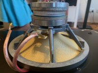
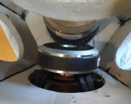
Standard specifications: Many misleading terms have been used to describe the paper preparation of the Lowther diaphragms, doping, age-conditioning, curing, varnishing, etc., leading to discussions & myths around old preparations, similar to the legend of Stradivari’s varnish. There is no magic formula. The standard process, used for many years, is to apply freshly prepared 'special pale' French polish to the made-up cone/voice coil sub-assembly prior to fitting to the motor. This soaks through the paper leaving pure shellac distributed through the paper fibres as the spirits dry. Sugar-like crystals can be seen on the surface of a freshly treated cone. A few months sees a uniform yellowing of the diaphragm due to the reaction of light & air with the shellac. The paper fibres are locked with the shellac to be stiff yet flexible; It is generally accepted that the driver performs optimally after this point, though the foam suspensions co-incidentally loosen up over this period, and this has more of an influence at the early 'break-in' period. Older drivers (pre-Thornton) mostly exhibit a dirty, patchy yellow appearance due to poorly prepared lower grade shellac, which does not cure well over time. Controlling the quality & preparation of the shellac is an all-round long-term improvement, but due to the cleaner appearance, some still think we do not shellac the cones. Standard spec. drivers will continue to be available as usual.
Premium Specifications: The main difference over the standard range is the treatment of the paper. In this process the paper is impregnated with our own in-house formular before cutting, forming & assembling. The 'curing' process is mostly complete by the time the unit is tested & packed, though improvements will still be noticed over the 'break-in' period. The new treatment reacts with the paper fibres differently to the shellac process, resulting in a more stable, consistent & dimensionally accurate cone. The impregnation formular, however, can only be made in small batches in our own workshop and will not scale up to industrial preparation. This limits production to the ‘premium-hand-made' scale,
with the inevitable expense involved. The premium diaphragms are also fitted with the new back centre, replacing the foam standard. The entire set of components is laser-cut, enabling greater control of consistency & accuracy over the die-cut standards. Laser cutting also allows us to make small detail modifications like rounding the points of the 'pips' that hold the voice coil to the inner cone, cut elliptical 'pressure-relief' holes to control the dual cone phase errors, adapt the turned edge of the inner cone to a more suitable paper weight & composition and re-design the assembly relationship of the inner / outer cone / back centre / voice coil - most of which
would have been adopted before, but not possible because of the limitations of the old die cutting. The result of all these adaptations is a diaphragm which excels in all areas, including appearance, with the Lowther logos, radial embossing, and consistency of paper surface & colour. The legendary hand-crafted double-wound speech coil and overall <>10.5g moving mass of the assembly are retained. Foam surround suspension is the same as standard.
Sound: Initially developed for use in the Edilia, testing in all driver models & cabinets showed a marked improvement in all areas. Diaphragms prepared straight-out-of-the box for our most critical 'test bed' - the Lowther-Hegeman with field coils - were received by everyone with amazement; described by various judges as 'game-changer', 'most significant positive step for Lowther in years', 'improvement in all areas of presentation of natural sound'. We are confident that the premium 'upgrade' easily justifies the enhanced price, and all customers are encouraged to hear the difference at our studio showroom. All of our top range handmade cabinets (TP2, Almira/Edilia, LHSR, Audiovector) will be fitted premium regardless of driver type. The premium diaphragms can be fitted to almost all existing Lowthers as an enhanced Re-cone, or LFL trade in.
Premium diaphragms: Key points - Changes / Improvements
Paper gsm weight & fibre type
Laser cutting & CAD design.
Lowther's own paper treatment impregnation process
Inner Cone improved, so:
Enhanced choice of phase plug /centre pole treatment
Aluminum or Silver voice coil
Radial embossing
Logos printed onto cones.
New back centre & assembly
Improvements in quality consistency, appearance, longevity.
Significant improvement in all aspects of sound presentation.