Hello,
While preparing new plans to release in the website, the model Manifold/MTB called my attention with a good response without any optimization, pure lucky. I'm calling Manifold/MTB because thy are basic the same layout with the horn difference, one is flared and the other is straight. But to add even more flexibility in the model I added flare option in the vent port too. Currently the model is available only for single driver.
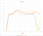
I took a Tapped Horn SS style I built using 15" driver and it's total box volume to be used as reference and I started to adjust the Manifold/MTB design in order to see what I could achieve with this kind of layout and for my surprise the SPL curve is definitely better for the same total volume ~300L. Maybe it can still suffer a little from port compression, even with the flare, maybe it can suffer also a little from thermals once the driver is inside a chamber, but the layout is very simple to build and with the option-1 I think it's possible to torque the screws from the horn. In the option 2 the bandwidth is wider (3 octaves) but it may requires access panel and compression ratio is probably too small. Particles Velocity in the vent port is around 24m/2 at mouth @ 800w witch is the driver limit.
What would you guys optimize in this design? for it's build simplicity and better SPL curve, wouldn't be this single driver Manifold/MTB be a better option compared to a Tapped Horn?
You can find additional data in the attachments.
While preparing new plans to release in the website, the model Manifold/MTB called my attention with a good response without any optimization, pure lucky. I'm calling Manifold/MTB because thy are basic the same layout with the horn difference, one is flared and the other is straight. But to add even more flexibility in the model I added flare option in the vent port too. Currently the model is available only for single driver.
I took a Tapped Horn SS style I built using 15" driver and it's total box volume to be used as reference and I started to adjust the Manifold/MTB design in order to see what I could achieve with this kind of layout and for my surprise the SPL curve is definitely better for the same total volume ~300L. Maybe it can still suffer a little from port compression, even with the flare, maybe it can suffer also a little from thermals once the driver is inside a chamber, but the layout is very simple to build and with the option-1 I think it's possible to torque the screws from the horn. In the option 2 the bandwidth is wider (3 octaves) but it may requires access panel and compression ratio is probably too small. Particles Velocity in the vent port is around 24m/2 at mouth @ 800w witch is the driver limit.
What would you guys optimize in this design? for it's build simplicity and better SPL curve, wouldn't be this single driver Manifold/MTB be a better option compared to a Tapped Horn?
You can find additional data in the attachments.
Attachments

Looks interesting, how does excursion at ~50hz compare?
I've only built one tapped horn but I'd argue provided you're not trying to achieve a particularly high cutoff, the build can be kept very simple ("stepped not flared").
I've only built one tapped horn but I'd argue provided you're not trying to achieve a particularly high cutoff, the build can be kept very simple ("stepped not flared").
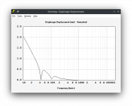
The excursion are basically the same. I attached the hornresp txt inputdata in the first post, it's inside the *.zip, so you can have access to all detail, like phase, group delay and others. Group delay is slightly higher and phase is better, it looks easier to integrate with tops.
Attached the excursion @ 2,83V
Black = opt1 vs Gray = TH SS
Attached the excursion @ 2,83V
Black = opt1 vs Gray = TH SS
Attachments
Oops I missed that, thanks. It's funny because I've been modelling (what I believe are) various incarnations of 6th order designs and ending up with very similar results assuming you optimise for a particular cutoff in a particular volume e.g. comparing to an S12BP style design (https://www.bcspeakers.com/resources/suggested-designs/). I guess I shouldn't be surprised, hoffman's etc.
Yes, you will find a lot of different models available here https://freeloudspeakerplan.rf.gd/
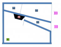
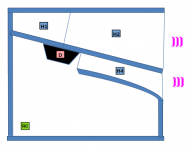
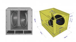
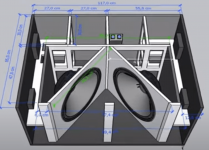
One think that is different between those models are the amount of internal panels (braces too), and the amount of fold, they make difference regarding internal box volume, the main loss I think is the fold. You can't properly see this difference only using hornresp ebcause i think hornresp celculate only the volume os the segments and elements you give as input, but when you go to CAD software you can see it. So from user point of view, and also transport point of view, the fair comparison for me is always the total box volume.
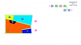
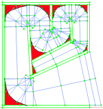
Check attached image for instance, it's not precise,the red areas are spaces that hornresp model does not take into account, but they consume a lot of internal volume. So, I think the designs that are able to better use internal volumes should be the ones to deliver better output response. Hoffman's lay still works.
One think that is different between those models are the amount of internal panels (braces too), and the amount of fold, they make difference regarding internal box volume, the main loss I think is the fold. You can't properly see this difference only using hornresp ebcause i think hornresp celculate only the volume os the segments and elements you give as input, but when you go to CAD software you can see it. So from user point of view, and also transport point of view, the fair comparison for me is always the total box volume.
Check attached image for instance, it's not precise,the red areas are spaces that hornresp model does not take into account, but they consume a lot of internal volume. So, I think the designs that are able to better use internal volumes should be the ones to deliver better output response. Hoffman's lay still works.
Attachments
If using the sub up into the 200Hz range, the Manifold/MTB would be preferable.What would you guys optimize in this design? for it's build simplicity and better SPL curve, wouldn't be this single driver Manifold/MTB be a better option compared to a Tapped Horn?
If crossing that high, drivers mounted with the cone, rather than the magnet into the horn would be smoother, though Hornresp won't make the distinction.
Changing the tuning on a ported design is easy, not so with a TH.
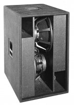
Your layout reminded me of the Welter Systems L-4 designed in the mid 1980's, which used four Electro Voice EVX150 15" "V" loaded with a 30" cabinet depth. The rectangular port depth was 8" if I remember correctly, resulting in around 38Hz FB, unfortunately I have lost the part dimension sheet.
I use the term "designed" a bit loosely, we cut down 16 of the original L-4 straight horns of 45" depth and converted them to a combination horn/BR. The design turned out to be quite successful for the time.
The cut down L-4 was a result of the brand-new EV MTL-4 spanking the LF output of the EV15B loaded straight horn L-4 in a flown side by side test at Prince's Paisly Park soundstage. Rob Colby had driven the L-4s in to hard clipping, the 100 watt voice coils started to expand and scrape and make horrible sounds. I thought not only had we lost the Prince tour, we would be reconing 16 speakers, fortunately after they cooled down they worked fine.
That walk of shame, and 45" being too deep to fit behind the fire curtain on many stages prompted the cabinet change and speaker upgrade, which resulted in way more LF in a 1/3 smaller package.
Though the EV MTL-4 quad 18” magnet in manifold design was near the same volume and had similar LF, the upper response of the EVX150 loaded L-4 was smoother and subjectively better in sound quality crossed over at 200 Hz into the straight horn mid-bass cabinets used above.
Art
I was not even born at that time 🙂 (81")
Manifold/MTB has a lot of potential witch can be explored more nowadays. Single or multiple per box.
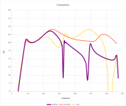
I added in the comparison the Paraflex Type C witch is also easier to build compared to TH but the way it works it need an small Volume penalty to delivery the same low frequency tuning reaching 319L witch is +6%, it improves the upper part of the bandwidth too with the accentuation in the kick area but it's narrow as Tapped Horn, so looks like Manifold/MTB still the winner.
We can add more designs in the comparison if it has the potential to take the 'st place (higher SPL or wider bandwidth with the same SPL keeping external box volume close as possible to 300L using the same driver).
Manifold/MTB has a lot of potential witch can be explored more nowadays. Single or multiple per box.
I added in the comparison the Paraflex Type C witch is also easier to build compared to TH but the way it works it need an small Volume penalty to delivery the same low frequency tuning reaching 319L witch is +6%, it improves the upper part of the bandwidth too with the accentuation in the kick area but it's narrow as Tapped Horn, so looks like Manifold/MTB still the winner.
We can add more designs in the comparison if it has the potential to take the 'st place (higher SPL or wider bandwidth with the same SPL keeping external box volume close as possible to 300L using the same driver).
Attachments
Since your post in my thread about the ROAR 12 problem I had been having, I have been playing with FreeCAD and the amazing resource that is your website.
By re-jigging your Manifold design to the same 800x600x430 size as the ROAR I am having troubles with, I have come up with this for a JBL 2217 woofer.

Manifold in black, ROAR 12 is in grey.

Where the Manifold design shows massive benefit to me is in the very simple construction (which can come from one sheet of ply with plenty left over for bracing), and of course the wider bandwidth. I can't seem to take the ripple out of the response without making big changes to the size, but it's nothing some gentle DSP shouldn't be able to fix.
Can you see any reason that this shouldn't work and why I wouldn't build it? I have confirmed that the speaker will fit in its modelled location and be bolted from the top.
This looks like the type of box that could be completed in less than half a day, which I cannot say for more sophisticated designs. It makes me think that there must be a catch, but I don't see it.

By re-jigging your Manifold design to the same 800x600x430 size as the ROAR I am having troubles with, I have come up with this for a JBL 2217 woofer.
Manifold in black, ROAR 12 is in grey.
Where the Manifold design shows massive benefit to me is in the very simple construction (which can come from one sheet of ply with plenty left over for bracing), and of course the wider bandwidth. I can't seem to take the ripple out of the response without making big changes to the size, but it's nothing some gentle DSP shouldn't be able to fix.
Can you see any reason that this shouldn't work and why I wouldn't build it? I have confirmed that the speaker will fit in its modelled location and be bolted from the top.
This looks like the type of box that could be completed in less than half a day, which I cannot say for more sophisticated designs. It makes me think that there must be a catch, but I don't see it.
Hello laxandredeyed,
Don't forget to enable the Sketch name Display in the settings, it will improve your experience. The way to enable it is indicates in the "how to use" section in the first 3 pictures.
This design is very tempting and I like it a lot too. As mention, the possible cons I saw are:
Thermals - If you assembly with the magnet inside the chamber the driver can heat more compared to a tapped horn leading to power compression, Art suggests to assembly with the magnet placed inside the horn to improve response but it will also improve thermal, but still, the air flow will not be as Tapped Horn because Tapped Horn is Band-Pass 6th order series, while Manifold is Band-Pass 6th Order Parallel so part of the air flow going to the Rear Chamber Port.
Port Noise - The lower Frequency is determined as a vented box from the Rear Chamber Port: H4 segment, to improve in this area I let the user the possibility to flare the port, so check the Particle Speed for the Segment H4 at mouth.
Both potential issue , if designed correctly might affect only PA application at High Power Level, for home use I think they can be ignored in the sense of the effect not in the design process.
I would just not recommend to build it if you still didn't found the issue for your ROAR, if the issue is with the driver this box will not work too. But once you have other driver It might be an option.
Well I decided to cut my losses and the ROAR build is firewood.Hello laxandredeyed,
Don't forget to enable the Sketch name Display in the settings, it will improve your experience. The way to enable it is indicates in the "how to use" section in the first 3 pictures.
This design is very tempting and I like it a lot too. As mention, the possible cons I saw are:
Thermals - If you assembly with the magnet inside the chamber the driver can heat more compared to a tapped horn leading to power compression, Art suggests to assembly with the magnet placed inside the horn to improve response but it will also improve thermal, but still, the air flow will not be as Tapped Horn because Tapped Horn is Band-Pass 6th order series, while Manifold is Band-Pass 6th Order Parallel so part of the air flow going to the Rear Chamber Port.
Port Noise - The lower Frequency is determined as a vented box from the Rear Chamber Port: H4 segment, to improve in this area I let the user the possibility to flare the port, so check the Particle Speed for the Segment H4 at mouth.
Both potential issue , if designed correctly might affect only PA application at High Power Level, for home use I think they can be ignored in the sense of the effect not in the design process.
I would just not recommend to build it if you still didn't found the issue for your ROAR, if the issue is with the driver this box will not work too. But once you have other driver It might be an option.
I'm going to attempt the Manifold MTB build shortly using JBL 2217 drivers (not the original drivers I had in the ROAR, but ones I tried in it).
Thinking about the voicecoil heat issue, I actually wonder how much benefit there is to placing the magnet in the horn. Granted, it won't be in a closed box, but it will still be in the narrow/tight end of an 800mm long horn with little room to spare. My intended application is low volume PA and bass guitar bottom end. Neither will be feed maximum power for hours at a time, although significant transients are to be expected with the bass guitar.
Should there me a maximum velocity I should be aiming to stay under for particle velocity in the port? The current sizing I have at the terminus is 618cm2 which is very close to Sd, so I think I won't have any problems, but feedback would be appreciated.
I think I can easily complete a prototype in a few hours, however after the sting of not being able to get the ROAR to meet my expectations, a critical analysis of my inputs would be very much appreciated.
Thinking about the voicecoil heat issue
Maybe it's not an issue, consider that the drivers are designed to be used in a sealed chamber, so once you are using vented chamber you are already in a best place. I particularly mention that because there people that want to optimize as much as possible the output, probably the voice coil heating could lead to 1dB~3dB lost at the maxim power output, but it will depending from what audio signal you are reproducing. You can deeper investigate or skip it.
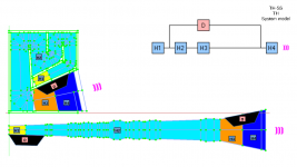
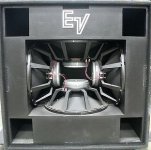
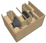
Check attached images, old manifolds had the drivers installed in a very tight place but they we closer to mouth, you can use the 3D to better check screw access.
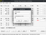
To check check Particle Velocity follow below indication and check others attached images too.
- Set the driver to be simulate at maximum power - Double click over Eg cell
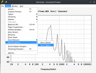
- Run the simulation and go to the Acoustical Power output Chart. - Click on Tools, Output and select the output you want to check (check all)
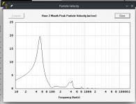
- After Hornresp data processing for single output, go to Tools again and click on Particle Velocity, select the place you wanna check the Speed
- Your current Loudspeaker data shows Particle Speed ~20m/s at 600W at Rear Chamber Vent Mouth.
Brian Steele has a webpage and he build some Proof Of Concept Loudpsakers with good documentation, some of them have vents, so I think he talks about Particle Velocity. Take a look: https://www.diysubwoofers.org/projects/
You can also reproduce a very well know project that people like and check it's performance, you don't need CAD to do this, you just need to reproduce Hornresp simulation looking for it's inputdata and compare to your project. Benchmarking is a very good tool 🙂
All projects take some time to became mature to be built, you can speed up this process but is important to give some time to your project too, sometimes it does't mean that you need to change something related to the box but instead it can be a time you need to collect data to increase your confidence level that you achieve the best performance possible and your design has no error.
Attachments
I was thinking in way to improve even more this manifold design regarding Particle velocity and Thermal Compression.
I check with David the possibility to increase the number of segments in hornresp to be used in the vent and it's not possible due to technical and time reasons so I came across with other two ideas:
Move the vent from the bottom side to up side in the rear chamber. The vent throat will be close to the driver making the air flow pass through it improving heat transfer with the driver. it may create some turbulence too and I don't know if this potential turbulence can be real issue for sound quality. This solution in terms of heat might be more effective then the one proposed from Art to invert the driver, because the low frequencies come from the vent, and low frequencies moves more air. Considering the cross sectional area, the heat transfer can be much better the a Tapped Horn if the sound quality is not affected.
If the new placement works, we could try to use exponential horn to smoother the throat or the mouth, while smoothing the throat it can reduce the turbulence from the air flow passing troughs the driver the heat transfer maybe will reduce too following the air speed. I f the smooth the mouth is improve sound quality better coupling with air outside the box. Construction will increase complexity when using exponential horn instead of parabolic one.
What do you guys think?
Any ideas are welcome.
Attachments

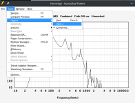
I found "similar" solution from 18Sound Manifold, the vent throat is very close to the driver motor, not exactly like my proposal where the driver is in fact in front of the vent. But is promissing.
The 18Sound plan and other details are attached, they published very good information for their box design. SPL curve is also included.
The 18Sound plan and other details are attached, they published very good information for their box design. SPL curve is also included.
Attachments
Good idea, heat flows towards cooler areas, a more direct path to outside air improves cooling.Move the vent from the bottom side to up side in the rear chamber.
The slug of air in a port moves in and out, little net air flow when the port is not turbulent. The higher the port velocity, the more "port compression", making more net air flow. Increased net air flow increases cooling, reducing power compression from voice coil heating impedance rise.The vent throat will be close to the driver making the air flow pass through it improving heat transfer with the driver. it may create some turbulence too and I don't know if this potential turbulence can be real issue for sound quality. This solution in terms of heat might be more effective then the one proposed from Art to invert the driver, because the low frequencies come from the vent, and low frequencies moves more air.
A 45 degree flare at both ends of the port would be a place to start, but I don't think the heat transfer vs velocity reduction compromise can be determined without comparative real world testing.What do you guys think?
Art
It has so many potential, I wish I knew it before I build my Tapper Horn backing in the time, but there was so many hype on TH, LOL
Other advantage of this model compared to TH is when you use a dual driver like 18sound, a push pull system that helps to reduce the vibration making one driver canceling other's force.
Looks like also RCF has provide Manifold products to the market. One layout has a combined vent below the driver with is nice to change a little the aspect ratio but it doesn't help with thermals.
Attachments
A friend had 8 P Audio 2226 woofers and was wanting subwoofers for his DJing. These are a low xmax driver that are seriously outclassed by modern designs, so I had my work cut out for me finding a box that would do something good with them. I designed a box around 250 litres based on LORDSANSUI's design, and my friend built them.
I have to say I am thoroughly impressed with the results. Efficiency is up almost 6db on a reflex alignment (measured) and outdoors they have no issue working sub 40hz.
He sent me this pic from his DJING last night. The 4 Eons are the weak link in the setup and cannot keep up volume wise withbthe manifold design.

I have built two similar boxes with JBL 2217 drivers for bass guitar use and I cannot imagine a venue where I will need to use both for a stage rig.
The manifold is easy to build and offers good efficiency gain (on par with some horns). I would say the design is good.
I have to say I am thoroughly impressed with the results. Efficiency is up almost 6db on a reflex alignment (measured) and outdoors they have no issue working sub 40hz.
He sent me this pic from his DJING last night. The 4 Eons are the weak link in the setup and cannot keep up volume wise withbthe manifold design.
I have built two similar boxes with JBL 2217 drivers for bass guitar use and I cannot imagine a venue where I will need to use both for a stage rig.
The manifold is easy to build and offers good efficiency gain (on par with some horns). I would say the design is good.
Fulcrum Acoustic's US221 dual 21" vents are oriented on the sides, and have a venturi-like shape.Looks like also RCF has provide Manifold products to the market. One layout has a combined vent below the driver with is nice to change a little the aspect ratio but it doesn't help with thermals.
The FA US212 is a dual 12" with a similar layout.
So that design is good or not?
yes, all benefits were posted.
I have to say I am thoroughly impressed with the results. Efficiency is up almost 6db on a reflex alignment (measured) and outdoors they have no issue working sub 40hz.
He sent me this pic from his DJING last night. The 4 Eons are the weak link in the setup and cannot keep up volume wise withbthe manifold design.
Thanks to share the image and to provide feedback. I'm happy once your friend is satisfied, his setup is really impressive for a small PA.
Interesting, I wish we could simulated different types of vent, I asked David as you can see in the link below, but it's too much work, and it's not going to happen.Fulcrum Acoustic's US221 dual 21" vents are oriented on the sides, and have a venturi-like shape.
https://www.diyaudio.com/community/threads/hornresp.119854/page-667#post-7248286
- Home
- Loudspeakers
- Subwoofers
- Case for Discussion - Would a Single driver Manifold/MTB be better than Tapped Horn?