For Sale Kevin Gilmore Dynalo MK2 Super Symmetry Parts Kit

Also known as the "MultiAmp" on the HeadCase forum where Kevin Gilmore hangs out, this is another project of mine that got shelved due to life happening.
The amp boards are completed, with the opamps and matched Bipolar transistor IC unpopulated(but included).
The GRLV PSU board has been mostly completed, with the missing parts included in the package. Power Transistors were not mounted as my original plan was to mount them to the side panel of a Galaxy Case, so proper heatsinks or mounting to a chassis is required(insulators included). A balanced headphone protector board is also part of the package, as well as various XLR connectors, parts for a Balanced to SE adapter, IEC power connector, and 25VA x 20 Volt Antec transformer.
Also included is a KG designed I2C controlled balanced relay volume control board, with software available on Head-Case
Please see the Thread on the Head-Case Diy Forum
$200 US plus shipping TBD depending on Speed and location.
PXL_20250621_214214307.jpg

Attachments

  • PXL_20250621_214807057.jpg
    PXL_20250621_214807057.jpg
    212.4 KB · Views: 41
  • PXL_20250621_214544770.jpg
    PXL_20250621_214544770.jpg
    381.3 KB · Views: 35
  • PXL_20250621_214320235.jpg
    PXL_20250621_214320235.jpg
    327 KB · Views: 38
  • PXL_20250621_214233685.jpg
    PXL_20250621_214233685.jpg
    355 KB · Views: 39
  • PXL_20250621_215016275.jpg
    PXL_20250621_215016275.jpg
    348.1 KB · Views: 39

Rollover - A Decent Amplifier with JFET in and MOSFET out

Uses LSK189 for input.
Buy at mouser.com: https://www2.mouser.com/ProductDetail/Linear-Integrated-Systems/LSK189-TO-92-3L-BK?qs=T%2BzbugeAwjjUrS49wFak%2Bw==
Uses ECX10N20 and ECX10P20 for output.
Buy for example at: https://gb.profusion.uk/uk/audio/transist/lateral-mosfets

The input JFET pair can be other JFET, too.
Bias in output is set to 300mA.
THD is 0.00020% with the LSK189.

Rollover LSK189_07.jpg

2-3in High Subwoofer Design Help

I'm building a subwoofer for the trunk of my Subaru Crosstrek.

I have 42.5in x 26in and would prefer the height be 2-4in. I'm having trouble with tuning of the box, as if the port is too wide the speakers go into over excursion, if they are thinner they easily go over 18m/s. I'm not sure how to model tapered waveguides or adding a flare in terms of port length. I'm a mech e but new to audio design, so joined here to learn as much as I could about complex analysis and subwoofer optimization.

I've tried sealed box, ported, 4th order (to basically act as a spring to reduce excursion, but I'm limited on tuning frequency because the back volume can't get any bigger without overexcursion), 6th order series and parallel, have played with 12in low profile sub, but don't know how to simulate downfiring and top must be encloseed as it will be the new trunk surface. The 12in is also pretty tall.

I'd be using an LX1300.1 with about 550W at a 2ohm load. Design shown is 6 Dayton Audio 2x7s. I'm trying to get low. I will have 2x 10in self powered el cheapos behind the driver and passenger seats, which will cover the 60-100hz range fine. That's what I did in the truck and it did the trick. I've never had low low bass and don't want to miss out on this opportunity with a brand new car.

I've attached a few pictures, but I've been through very many iterations, these are just some recent ones to show the process of building the subwoofer.

I'm also not opposed to passive radiators, but the only 2in or less ones are cheapo knockoffs with no TS parameters for excursion or moving mass or anything so I don't know how to begin that calculation.

Attachments

  • Dayton 2x7.png
    Dayton 2x7.png
    290.1 KB · Views: 156
  • Dayton 4th Order.png
    Dayton 4th Order.png
    2.1 MB · Views: 178
  • Dayton Ported.png
    Dayton Ported.png
    3 MB · Views: 170
  • Excursion.png
    Excursion.png
    256.9 KB · Views: 152
  • Response.png
    Response.png
    458.1 KB · Views: 146

Taramps TS2000x4 confirm channel dependency

I’ve recently repaired this amp but I find an occurrence I want to confirm, IRFB5620 are the output and a cross of IRFB4227 was referred as sub, after installed they got hot and no drive waveform, I swapped to another working channel and still warmed. Nothing else was damaged in the amp just one bad output. It was when I purchased the IRFB5620 then the amp worked.
Another puzzling problem is whenever I pulled the output from any one channel, the adjoining channel won’t produce any waveform regardless of four “independent seeming” channels (that is 1 or 2 and 3 or 4). Therefore, if one channel goes bad there is no three channels (like class AB) even if you remove the damaged outputs and free up voltage rails.
Can someone explain?
IMG_7756.jpeg
IMG_7755.jpeg

JBL Garage Speakers

Hello All,

Cleaning out my garage to make room for a treadmill and a place to roll around on a swiss ball.

There are boxes of mostly JBL drivers that need to go. I may sell some along the way.

For entertainment I am planning a pair of 1 to 2 cubic foot speakers attached to the storage loft above.

There are more than a few options, the speakers likely will be 2-way with 12" woofers plus Compression Drivers / wave guides attached.

In the storage boxes there are 2204H, 2206H and 2217H (a 14 inch driver). I am leaning towards the 2204H's, they model a little lower in frequency response.

For the CD's there are several options, I am liking the 2453 SL mounted with the Progressive Transition 6-1/2" X 12" 90 X 50 wave guides.

Any thoughts or ideas?

Thanks DT

Inspired by the days of Zilch (RIP)
  • Like
Reactions: Arez

Amp Camp Amp - ACA

:Popworm: Looky Here... Original article by Nelson Pass:
Amp Camp Amp #1
😀
______________________________________________________

Info for Amp Camp Kit (updated by Moderators)

Here's the ORIGINAL step by step photo build guide: ACA illustrated build guide

A new Build Guide for the V1.6 Two channel Chassis in the diyAudio Store.
Amp Camp Amp V1.6 Build Guide - diyAudio Guides

The small changes of the 1.8 version.All ACA’s that have 2 channels in one chassis can be converted to Version 1.8 which only requires buying a different rear panel switch and some re-wiring of the rear panel. Amp Camp Amp V1.8 Change Information - diyAudio Guides


The link below is to a Step by step build video by Patrick Norton on his TekThing website. He makes an error in cutting out the thermal insulator and leaving the backing on. Thebacking just peels off, no cutting required:
February 2016 Patreon Build Video: Amp Camp Amp Dual Monoblocks! - YouTube

See post #1453 for a tweak to the original V1.0 circuit boards. It’s not essential but should improve the sound. This tweak has been incorporated in subsequent versions (1b & 1.5, 1.6,1.8). if you have those circuit boards or kits it's already added to the board, and the part (R15) included in the kits

An ACA thread with lots of great ideas which may or may not improve the amp to your desires:
ACA amp with premium parts

Here’s a thread discussing the kits from the DiyAudio store for V1.6 and V1.8
Amp Camp Amp Kit 1.6/1.8

And here’s the link to the kits:
https://diyaudiostore.com/collections/kits/products/amp-camp-amp-kit?variant=7072933085218

Notched top plates in vintage gear?

Working on some vintage Jensen P15LL woofers/midrange 15" drivers and doing re-cones. They are designed for peak performance from ~50 - 3000 Hz. 40 Watts. Commonly found in Leslie speakers ~1955 - ~1964.

I've noticed that the top plate is thicker across the surface, but down in the gap it is notched back some. So the top plates are ~0.6" thick, but it is notched back so that the part closest to the voice coil windings is only 0.54" thick. As originally built, the voice coil is centered on this 0.54" height and not the overall thickness of the top plate.

See the attached drawing.

Is it common to have an area notched out like this in the gap? Does the thickness of the plate closest the windings dominate the magnetic field location?

Attachments

  • Screenshot 2025-06-21 at 1.48.50 PM.png
    Screenshot 2025-06-21 at 1.48.50 PM.png
    205.2 KB · Views: 40
  • Screenshot 2025-06-21 at 1.59.54 PM.png
    Screenshot 2025-06-21 at 1.59.54 PM.png
    619.4 KB · Views: 36

Hi there !

Hello everybody,

Very happy to join this forum !
I am a humble music enthousiast and have recently upgraded my hifi audio setup and i came to realise that my Denon PMA-560 is having sound quality issues. My quest in troubleshooting this issue led me on this great website and here among you.
Even though I have been dismounting electronic devices since I was a kid, I don't have a lot of knowledge in electronic circuits and/or components. I am hoping I will learn a few things by hanging out and asking questions on this forum. Hopefully I'll be able to help others in the future !
My english is pretty good but it isn't my mother tongue so I might do some mistakes, apologies in advance 🙂


Cédric from Switzerland

Folded Cascode CEN IV with fixed Rails

Exactly 11 years and 2250 posts after the original CEN IV, the simple circuit still have many fans and positive feedback.
But the difficulty of having to use floating power supplies remains.
Especially, if one is using 2 channel balanced mode outputs, 4 of these floating supplies are required.

https://www.diyaudio.com/community/...lution-of-a-minimalistic-iv-converter.195483/

The question has been -- is it possible to have at least similar performance but using fixed rails ?
In the original thread, the use of current sources between fixed rail and IV circuit has been discussed.
11 years later, with experience gained from the revised XCEN converter circuit, the puzzle has finally been solved.


220407 FC CEN IV Proto1 Top.jpg


So here you are. Happy Reading.


Patrick

.

Attachments

Limestone turntable, help needed with motor and drive

IMG_2314.jpg
Dears,
This is second (and last) blast from the past project that I will publish. Its from early 2000's when I was very much into doing different audio things.
Other of my old projects have no much difference from usually seen executions, so I will skip those.

As elementary school kid (in 1977), my older sister left me her BSR turntable system (in Yugoslavia than called Tosca) and some 50LP's, good stuff of the time, Leonard Cohen, Dylan, Cat Stevens, Janis Joplin, Roberta Flack, Jimmy Smith, some classic and so on... Anyway, I felt in love with LP's and HIFI forever, this still goes on.
Anyway, few friends (actually their parents) had Thorenses, Sondeks and Duals, , I always wanted proper turntable. By the time I made my own money, CD came into play and I bought one of the first Philips CD player.
Few years after I still wanted TT, bought one crappy example, throw it away and decided to make my own. Intention was not to make hi end piece, but to make vintage looking TT similar to those that I was wishing for:
This is the result:

Simple comparison between Hornresp and AKABAK. Beginner's mistake or?

Hello friends,

Please help me understand what I am doing wrong. I have tried to learn the programs Hornresp and AKBAK by building simple models of horn speakers in both programs and then comparing the results. I have discussed the results with Mr. Chatgpt because I cannot get the comparison right. I do not really know what to expect in terms of similarity between the results. I am not very knowledgeable in electronics or theoretical audio technology but I still think I understand that the sound pressure curves and impedance curves should be quite similar for simple models with these two programs. Mr. Chatgpt has been very helpful I think but "he" has not managed to figure out what I am doing wrong.
I have placed an infinite baffle in the same plane as the horn mouth to get a 2 x pi radiation angle. The speaker element is this 15-inch element:
https://loudspeakerdatabase.com/BC/15DS115_8Ω

I think the impedance curves match quite well, at least the frequency of the first peak, but not quite the level (Hornresp: 4.4 Ohm@125Hz, AKABAK: 3.2 Ohm@128Hz). The second peak matches better in terms of level but worse in terms of frequency (Hornresp: 2.46 Ohm@284Hz, AKABAK: 2.2 Ohm@267Hz).

What bothers me the most is the difference in sound pressure for the two models. AKABAK has a first peak already at 54 Hz and sound pressure 74 dB. This peak does not exist in Hornresp which has its first peak at 125 Hz and 108 dB. The next peak in AKABAK is at 135 Hz and 68 dB. This does not match very well with Hornresp.

Attachments

  • Skärmbild 2025-06-14 204428.png
    Skärmbild 2025-06-14 204428.png
    12.2 KB · Views: 68
  • Skärmbild 2025-06-14 204918.png
    Skärmbild 2025-06-14 204918.png
    5.1 KB · Views: 63
  • Skärmbild 2025-06-14 205013.png
    Skärmbild 2025-06-14 205013.png
    9.7 KB · Views: 55
  • Skärmbild 2025-06-14 205055.png
    Skärmbild 2025-06-14 205055.png
    8.9 KB · Views: 58
  • Skärmbild 2025-06-14 205235.png
    Skärmbild 2025-06-14 205235.png
    69.1 KB · Views: 56
  • Skärmbild 2025-06-14 205513.png
    Skärmbild 2025-06-14 205513.png
    173.6 KB · Views: 57
  • Skärmbild 2025-06-14 205706.png
    Skärmbild 2025-06-14 205706.png
    26.3 KB · Views: 58
  • Skärmbild 2025-06-14 205753.png
    Skärmbild 2025-06-14 205753.png
    21.5 KB · Views: 58

Hello everyone who likes audio and video I have a small problem finding a service manual for the Vincent SV 233 amplifier, one channel stopped playin

Hello everyone who likes audio and video
I have a small problem finding a service manual for the Vincent SV 233 amplifier, one channel stopped playing and as I learned there are people here who own it, I would be very happy if someone could help me and send me the diagram, it would be a shame not to fix it
Thank you very much in advance

Active crossover for three way actively amplified speaker

I've got Carver TFM-15, TFM-25 and TFM-35 amps that I use for a three way actively amplified speaker consisting of:

Altec 811B horns
Eminence Delta pro12A for midbass
Dayton Audio 12" subs

I currently use a DBX 234XS crossover which works fine except there is solid state hiss heard in the horns due to the TFM-15 not having any markings on the front panel for the input level controls nor does it have pots with detents. So there's no easy way to ensure the controls are set the same way every time the system gets used to DJ with.

I would prefer an analog crossover, but if there's a DSP crossover that is good enough for actual HI-FI use I'd be interested in that as well. The crossover also needs to be low noise as well given the Altec horns are quite efficient.

Hello everyone. I'm Kosta

Using 2x ECC83S Instead of 6AN8 in Dynaco Mark III – Advice Needed

Hello everyone,

I'm currently building a Dynaco Mark III-style mono tube amplifier and I'm planning to replace the original 6AN8 driver tube with 2x ECC83S (12AX7) tubes for each channel. I understand this involves redesigning the driver and phase splitter stages to suit the dual-triode layout of the ECC83S.

My main question is:
Has anyone successfully implemented this conversion, and are there any confirmed, working schematic adaptations you could share?

I want to be absolutely sure before committing to this layout and buying tubes. Any practical experience, schematics, or advice on wiring, gain structure, or tonal results would be very much appreciated.

Thanks in advance for your help!

Gold mine of DI¥ audio tubes schematics from Japan

***** Gold mine of DI¥ audio tubes schematics from Japan *****

Lucky i was to see such extraordinary DIY projects archive with vacuum tubes i share this treasure with all forum members.
Infinite THANKS for hobby amateurs in Japan who patiently scan this MJ magazine articles over the years.
Every month we get new ones available on line in pdf format
lot's of OTL amplifiers , Sakuma San articles
Et cetera

Please enjoy & respect this precious library 🙂

click on direct download link Schematic Treasures: DIY tubes audio articles HOME

and menu and titles Google Translate version in English

どうもありがとうございます
Domo arigato gozaimasu

Phillips Cassette Player

Hi there,

I have a Phillips Cassette Player with a broken motor. I am looking for somewhere in the United States or Europe to get this fixed.

Type: EL 3302A/15G
Voltage: 7.5V
Frequency: 50/60 Hz
Manufacturer: Philips
Motor markings: WR 01 941


I believe that the motor I am looking for is a small DC motor, likely a 7.5V brushed type used to drive the capstan and reels.

Does anyone have any advice to where I can find one of these and/or get this fixed? I am located in California, but again, can send it anywhere.

Thank you.

Attachments

  • IMG_5680.JPG
    IMG_5680.JPG
    728.5 KB · Views: 144
  • IMG_5681%202.JPG
    IMG_5681%202.JPG
    458.1 KB · Views: 142

Testing of defaced FETs

Does anyone here want to help in trying to unmask the defaced FETs that you find in some amplifiers? The following is what you'd need for basic testing. Having this work distributed to a large number of techs could defray costs and tests of the same FETs by different techs could help confirm values.

A 12v power supply

A 2 ohm (other values would work but a standard 2 ohm would simplify) dummy load or current limiting resistor (25w or larger)

A way to accurately measure current (any multimeter capable of measuring 10 amps is good enough)

A standard multimeter to measure DCV.

Some form of heatsink to clamp the FET to during testing

Understanding Bessel array radiation patterns?

So using the 5x derivative as it’s the only one Keele thinks has a practical purpose……the two outermost drivers are the main energy drivers of the system with each unit representing one 1/4 wave spacing…….would that suggest that the overall dispersion pattern would be equal to that of the diameter of the same size cone?……let’s say the 5 combined distance is 8”…….are we now talking about the same dispersion characteristics of an 8” cone or point source?………

Swap new toroidal power transformers with 2x33V for 2x25V transformers

I would like to swap two brand new toroidal power transformers with epoxy filled center, each with 180 VA 2x32 V, for two new or nearly new transformers with 2x25 V -2x24 V to 2x27 V will also work. One with 500 VA will also be fine.
If higher-quality transformers are available, financial compensation is also possible.
And if you only want to get rid of suitable transformers, I'm interested.
Because of taxes, shipping costs, and so on, preferably from Tschömoney or the EU.

Thanks for looking

Attachments

  • 2x33V_1.JPG
    2x33V_1.JPG
    148.7 KB · Views: 32
  • 2x33V_2.JPG.JPG
    2x33V_2.JPG.JPG
    116.8 KB · Views: 28

Some Single-Battery Guitar Preamps

Single-Supply Preamps For Guitar

Here are six preamps for guitar using op-amps; each operated from a single 9V battery as the power supply, thus making them suitable for stomp-box applications. Sources for the diagrams are noted with the diagrams. The circuits are faithful to original diagrams but for minor changes, such as the adding of an input level control or the use of a pot in a negative feedback loop to provide the user with a gain control. However, while based on proven designs, these designs must still be considered experimental. Also, the diagrams originally posted had flaws, which were corrected according to advice from forum members here, who I thank for their help. The diagrams shown now are updated versions (but some may be updated again if needed).

1748362886140.png


The specified IC is the OPA2156 dual low-noise op-amp IC, but an original TI unit can be expensive and may take a long time for delivery. So, I have listed a number of pin-compatible substitutes at the end of this post, all of which will provide good results.

The next circuit features a Baxandall type of 2-band tone-control, followed by one with a Fender-style 2-band control, which works differently from the Baxandall-type, though both leave the mids fixed. For those who prefer three bands, all other circuits below involve 3-band Fender-style tone stacks.

1748362972891.png


Note the seemingly redundant Tone control at the output below. That is included to provide an additional means of shaping high-end response.

1748363046332.png


What follows next are the preamps with the 3-band tone-stacks having default Fender Bassman part-values.

1748363085578.png


Consider the difference in the way the input and output jacks are shown below. This would be a good way to do the foregoing circuits too, but I show this configuration only for the last two circuits. This one also has a fuzz circuit using diodes, providing clipping without having to overdrive op-amps. But if that is desired, an older dual JFET-input IC can be considered, having minimum supply voltage <= 4.5 V, such as the LF353.

1748363154488.png


The circuit below likewise has a diode-type fuzz circuit, but which is highly adjustable.

1748363185469.png

1748193975184.png


Here is the pinout diagram for a dual op-amp, along with pin-compatible example ICs.

1748194023631.png


ICs listed here should perform satisfactorily for the electric guitar and offer the least noise and distortion for circuits operated using a single 9V battery. They were chosen from among the best op-amps available today but whose minimum supply voltage is <= 4.5 VDC, since half of 9V is 4.5V, and a single-supply circuit sets the zero signal-reference operating-point midway between ground and the supply.

To get more distortion than the diodes provide, by overdriving a given circuit, use the LF353 instead of any of the ICs listed above. It is an older op-amp that will work with a single 9V battery as the supply and is a JFET-input op-amp, which means its overdriven tonality is preferred over that of most non-JFET-input op-amps. However, it will also work fine without being overdriven, and will not drain the battery nearly as fast as those listed above.

Note On Fuzz Circuits: The diode-based fuzz circuit used in the last two preamps are based on article “Build The Mod Box” by Thomas Henry and Jack Orman, in the May 1997 Electronics Now magazine (p.45). Obtain the article free online with this link.
https://www.muzique.com/news/images2/Mod_Box_May_1997.pdf
It originally specified the TL074 quad op-amp since it had four sub-circuits, and was operated from a split-supply. And despite being somewhat dated (25 years old), the circuitry has remained valid to this day, though I have adapted the diode arrays to conform to a single-supply circuit.

Additional Notes: Most circuits here are based on designs in the book “Building Electric Guitars” by Martin Koch. [$33.56 on eBay.] But the input stage of the second preamp is instead based on a design by Craig Anderton appearing in the Nov. 1981 issue of Guitar Player magazine. [Original issues start at $10.00 on eBay.] Those exact circuits cannot be found online, so a link to them is not available. Yet, I have depicted them accurately but for the minor additions I mentioned at the beginning of this post. Furthermore, while I receive much help diagnosing the diagrams I posted at first, I supplemented that help with online research, and an electronics textbook used at an accredited university. Consequently, all diagrams above have been updated and should be viable, but I would still treat them as experimental until after breadboard testing efforts have been completed.

Final Note: For comparison, the diagrams originally posted have been retained in the Attachments folder at the bottom of this post, while the updated versions are also there. I am embarrassed by the original ones, but proud of the new ones, though members who helped me with them deserve lots of credit. One thing should be mentioned, however, regarding the 0.2uF capacitors going to ground on the second stages of most of the diagrams. That, along with its associated resistor, sets the low-frequency cutoff for the associated op-amp at 80 Hz for 6-string guitar. But for bass-guitar, and 7-string or 8-string guitar, make it 0.43uF, for a 40 Hz cutoff. And for no low cutoff at all, it can be omitted. And by the way, the following replies correspond to the original diagrams, not the new ones. So, if you want to know what they are talking about, refer to the old diagrams as left in the Attachments.

EOF

Attachments

  • 1748193680526.png
    1748193680526.png
    72.3 KB · Views: 288
  • 1748193761606.png
    1748193761606.png
    96.3 KB · Views: 289
  • 1748193781708.png
    1748193781708.png
    76.1 KB · Views: 280
  • 1748193844418.png
    1748193844418.png
    86.9 KB · Views: 275
  • 1748193909540.png
    1748193909540.png
    77.6 KB · Views: 250
  • 1748193958247.png
    1748193958247.png
    81.6 KB · Views: 240
  • Like
Reactions: dazcwl

Revised Single-Battery Guitar Preamp Circuits

Verified Single-Battery Guitar-Preamp Designs

Here are six guitar preamp circuit designs, each shown powered by a single 9V battery. I posted some of them in this forum a while back but have lately revised them using a simulation website; CircuitLAB. 
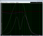
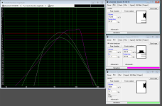
www.circuitlab.com After working out all the bugs in a given diagram (very few thanks to help from my friends here at DIYAudio), the software at CircuitLAB displays a graph of circuit performance which verifies the design’s viability and allows for checking how changing part-values affect the circuit.

I have not built and tested these circuits. Thus, though verified, they must be viewed as experimental, so a prospective builder should breadboard test a chosen circuit before committing to a fully soldered build. But it is assumed that anyone contemplating using any of my designs as a basis for a new project is already an experienced technician. Hence, I cannot take responsibility for the outcome should someone base a project on any of my designs. I can only assure readers that they were verified using simulation software designed for that purpose. And I highly recommend CircuitLAB, if interested. They only allow one free trial project, but I like it so much I’m paying for it.

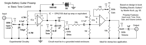
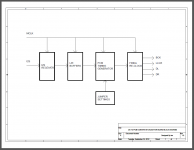
The diagrams involve various features and should be taken case-by-case to see which one or more may interest a possible builder. Also, it is allowed that subcircuits from one can be used in another or even used in a project not of my design. Notes are included in the diagrams to help make things clear and for specifying part numbers. First up is the most basic design, with Tone, Level, Bright, Drive, Gain, and Volume controls.

1750527114794.png


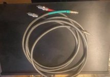
I have retained the symbols required by the CircuitLAB simulator for inputs and outputs, but a builder can simply imagine replacing them with female 1/4-inch phone-jacks, as shown below.

1750527191030.png


Inspiration for the input stage of the above preamp design must be credited to Austrian author Martin Koch, who wrote and self-published the book Building Electric Guitars, of which I have the 2nd Edition, 2001. The Circuits in question are on pages 49 and 60, but I made enough changes, compared to the originals, and as the output stage is of my own design, that I can claim the overall design as my invention. But in the interests of full disclosure, I have cited Koch as the source for the input stage.

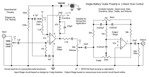
Next is a design in which the input-stage was inspired by a Craig Anderton design appearing in a 1980s issue of Guitar Player magazine. Notice how he uses positive and negative feedback. The 2-band tone-control is an even older design, found in many op-amp applications circuits but which originated in the tube-amp days, specifically 1950. Called a Baxandall control, after its inventor, the first such circuit had a tube instead of an op-amp. For an online reference, see site https://tonestack.yuriturov.com, and select option Baxandall Active Dual Bass Cap. Combining the two circuits makes this diagram my creation, though I have just given full credit to whom it is due. [This is not a James tone-control, which uses much the same circuit but passively. Thus, the James control is often called a Passive Baxandall tone-control circuit.]

1750527668045.png


A little thinking reveals how the negative and positive feedback controls interact. The negative feedback pot is labeled “Overdrive” while the positive feedback pot is labeled “Gain”. And this makes sense because the Overdrive pot’s position, controlling negative feedback, makes the op-amp operate more cleanly when more feedback is applied, but otherwise allows the op-amp to approach its maximum output rating, causing distortion. This is why the arrow near the pot is in the opposite direction to the actual amount of negative feedback applied, so turning the pot clockwise makes the op-amp get louder. On the other hand, the Gain control sends feedback to the positive op-amp input, thus making it approach its maximum gain rating when more feedback is used, also causing distortion. Ordinarily, you don’t want positive feedback for an op-amp because of the danger of the device possibly exceeding its rated maximum-gain limit, which could in fact burn it out if unchecked. However, it's probably safe to assume that Anderton figured everything out before publishing the circuit, so the device will not exceed its rated maxima (with given part-values), even when overdriven.

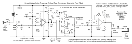
Next up is a preamp circuit in which the input and output stages are completely of my own design, though obviously the tone-control is a 2-band Fender-style tone-stack, and inspiration for the diode-based fuzz circuit came from an old Electronics Now magazine article.

1750527901839.png


Specifically, see article “Build The Mod Box” by T. Henry and J. Orman appearing in the May 1997 issue, pages 45-49 and 60. Surprisingly, the article is available online. Here is the link. G:\Ebooks\ELECTRONICS\Magazines\Radio-Electronics\EN-1997-05.pdf

In the text of that article, and confirmed in other sources, germanium diodes and LEDs give better sounding fuzz than do silicone diodes. Also, an imbalance between the positive-going and negative-going diodes in an array introduces more even-order than odd-order harmonics into the fuzz tone. In the article, one diode was used in one leg of their array but two in the other. Here, I allow users to select between one, two, or three in different legs. However, only experimentation will reveal whether this arrangement will result in sounds pleasing to the ear. As an addendum in that respect, consider a well-written online source on diode distortion titled “Producing Asymmetrical Clipping”, linked here. https://www.muzique.com/lab/warp.htm

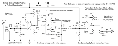
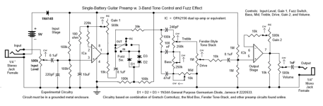
Below is a more elaborate version of the same kind of preamp, this with 3-band tone.

1750528024309.png


Note that I rely totally on Yuri Turov’s tone-stack calculator (cited above) when getting part-values for my tone-controls, instead of tediously crunching numbers like I used to do. In some cases, I use default values, as above, but in others I tailor the values to my personal preferences. For instance, I sometimes adjust them to increase the mids of the above tone-stack, as the default values (based on the original Fender design) have a tremendous dip in the mids when all the pots are at their middle positions. I also like to give it more treble and set the response graph as high in amplitude as it will go.

In the preamp design below, I use much the same op-amp circuits original to me but pair them with well-known classic distortion circuits that have been used in the past by many stomp-box makers and hobbyists. Craig Anderton was the first to discover that the inverting buffers in the CD4049 hex-inverting buffer IC produce an overdriven tone similar to that of a saturated preamp tube. Some online sources say his idea was first published in Guitar Player magazine but he had actually published it long beforehand in his book Electronic Projects for Musicians, from Amsco Publications (first copyrighted in 1975 but later copyrighted again in 1980, as far as my copy states, but I don’t know if there are later editions). In my copy, it’s the “Tube Sound Fuzz”, p 170 -173. Below are two identical clones my source says are used in MXR’s “Hot Tubes” pedal.

1750528285677.png


I was unable to confirm that MXR made a pedal called “Hot Tubes”, but I did find one by Electro Harmonix. See that circuit here. hottubes.gif (739×706) That stomp-box is itself quite dated, and is only available used, for instance, at www.guitarcenter.com. I have also noticed that many modern fuzz pedals use diode clipping instead of overdriven op-amps, or they are sticking with discrete transistor designs. However, whether the above circuit can compete in the tone department can only be known if the circuit is built and sound tests are performed for comparison. Yet, my design should sound very much like the old-school Electro Harmonix Hot Tubes pedal.

Finally for this post, the preamp circuit below features an octave circuit, though the source for it touts it as providing a distorted octave sound. Apparrently its octave tonality is pleasing to the ear. Here, I use a summing-amp to mix the direct and octave signals

1750528468108.png


Octave Circuit Source: David Morrin, at https://www.diystompboxes.com/smfforum/index.php?topic=186086
Note: You must sign up with DIY Stompboxes to access the original schematic, which was posted in their forum. However, I have rendered the circuit accurately between the Octave Drive and Octave Level controls, exclusive, while the Trim pot was in the original design, but I renamed it.
That site’s home page is linked here. https://www.diystompboxes.com

To replace the battery with a standard regulated power-supply, here’s an example circuit.

1750528592635.png


However, you can also use a 9V adaptor commonly used for stomp-boxes. Yet, here’s a tip for how to make the cheap ones work better (more like a regulated supply).

1750528677565.png


While the adaptor (wall-wart) is relatively inexpensive, a suitable choke is rather costly. However, if you can find a cheaper one that will work, that’s OK. What’s specified in the diagram are mere examples, provided for the reader’s convenience.

As reported by the designer in the noted Circuit Reference, this circuit will make an ordinarily noisy unregulated +9V wall-wart perform like a regulated supply. But on the other hand, Guitar Center has a 9V wall-wart they list as a “regulated” supply for stomp-boxes. [Probably Zener regulated, which is perfectly acceptable.] It’s only $19.99. The Live Wire PH17000 “Slimline” Power Supply, item # 1342450362499. https://www.guitarcenter.com

I make no apologies for using old circuits to create my designs. In my experience, if something works in electronics, it will continue to work as long as parts are available. And there is something to be said about the fact that many new commercial stomp-box circuits are based on old circuits or are reissues of old circuits. Proof of desirable tonality, however, will be known only should one of my designs get bult and is put to the test.

EOF

DIY Bookshelves to replace monitors

Hi there.

Currently, im running JBL LSR305s alongside a dayton MX15-22. The JBLs will play happy to about 55hz and the sub up to about 60hz, which makes for some decent response with a little EQ.

However, I'm wondering if there's any performance left on the table mids and highs wise. Sub is tight and clean, and will happily play as loud as I want and well below 20hz, but my monitors feel a tiny bit lacking, especially when I'm turning them up to 90-95dB (i know it'll blow my ears out, I just want to be distortion free as loud for as I wanna play them). I feel like at higher volumes, I run into a little woofer compression, and despite the measurements being pretty flat it's lacking warmth. I've found it hard to EQ that warmth you get with larger floorstanders and bookshelves in with this little system, at least comparing it to PMC Prophecy 9s I heard not long ago.

My goal is to get to about 40hz or so in a relatively small cabinet (probably 0.65-0.75cuft net). Does anyone have driver suggestions for 8" or 7" drivers around £100? I was looking at the Dayton SIG225 originally, but the RS180-4 and ETON 7-612/C8/32 have caught my eye - wondering if the ETON driver is worth the extra £50 per pair compared to the RS180.

Tweeter recommendations also welcome, but I wanna focus on the woofer and get the bulk of enclosure design outta the way lol

Thanks in advance!!!

I have 3 Jensen P15MNS 2 need recone

I would sell them or trade for parts for a marcel DAC other than the JLsounds i2s to usb converter
i already have 2 r cores with 4 secondaries too.
I need regulators,
a marcel dac
pcm to dsd
and some anti jitter stuff.
If someone does good deals on the recone or has extra kits I am interested as well and can pay.
I also have 2 baldwin leslies
I am in charlotte NC

Love all yall

OMG I have these super shallow wide speaker cabs i have to cover the front hole in so to make them tall skinny deep and narrow but thats for another day

keep healing the world with music everyone.

were almost there

"mp3 will die soon and the fraunhaufer corp who helped us shrink the 44.1khz 16bit codec down small enough for 1998 56,6 dialup modems will be forgiven for doing such great psychoacoustical research."

Experience of using AI programmes for loudspeaker design

I know very little at the moment about the ability of AI programmes to generate sensible, or good data for typical 2 - 4 way loudspeaker design, hence my ramble questions below.

The candidate AI programme I am asking about here is Claude.ai. I assume the free version or do I need to go to the subscription version?

Kindly, can somebody provide a brief overview of what the free version would allow me to achieve, is it viable for loudspeaker design ?

Forum member mechano23 using XMachina has already shown that you can make a well received design, if the correct parameters are applied. I definitely do not want to have to spend three times the amount on crossover components compared to the £80 driver I wanted to used. Cost are one constraint or parameter to be entered?
Do they accept FRD and ZMA file data, do they need real data or can they work from manufacturers data sheet data and apply diffraction loss other cabinet effects, once cabinet data is entered?

Within the questions I am not sure how many microseconds these things take to produce an output, or does it take the course of an evening whizzing around searchable data on the internet before it provides an answer? As a preference I like graphical display in the time and frequency domains as they allow me to have a indication of what is going on

In terms of model training for a loudspeaker design, are you allowed to describe the parameters that would allow you to measure pre defined standard say IEC 60268-21, the Harman preferred curve, BBC, Stereophile reviewers listening room, or audio express recommendations etc.

If not part of the AI and it is up to the designer to provide parameters, maybe we should start listing what parameters we think are relevant.?.
Does somebody want to share their design an parameters to enlighten me. How would it handle a remake of a Spica TC50 using Purifi drivers for one example and currently available Peerless drivers for the other.

Finally I assume as the models learn over the course of time one user in Shanghai will end up with exactly the same Xover design for a certain set of drivers and optimum box size, as somebody in Jakarta, if they use exactly the same choice of drivers?

Any help, thoughts or guidance much appreciated.
  • Like
Reactions: Netlist

Tubes4HiFi SP14 really noisy!

Hi,


I ordered the kit without the chassis, as I wanted to build my own - plus I wanted to try to save some $$$’s
Smile


I’m getting a LOT of noise out of this…

All the voltages are as they should be.

B+ is 276vdc
H+/H- is 6.13 and 5.87
Voltage drops from 313 to 276 across D13 (both sides…)
6.43vac on heater from transformer


I have checked, double and triple checked the wires from all RCA inputs/outputs. The ground bus and all the connections to that, the ground to the circuit board from the bus. I’ve gone over the input selector, and all the wires coming and going from that. All the connections from the selector, through to the gain and volume controls. The output from the volume to the board, and ground wire are as outlined in the instructions.

I did not install the tape switch, and ran the wires straight from selector to the gain pots.

There are two things I changed as far as the power supply goes. I used an old school toggle switch in place of the power switch that came with the kit. And I accidentally reversed the red and black primaries to the transformers from a hot/neutral perspective. But I don’t think the transformers care about hot/neutral?

The noise is the same regardless of gain/volume settings. It’s the same in both channels. It gradually comes up in volume as the unit powers up. As soon as it’s powered off, it disappears but music keeps playing until it fades away.

The noise is the same, albeit with different volumes, if I run it into my DIY Hiraga Super 30 Class A SS amp, or my DIYAudio VFet SE SS amp.

Thank you for taking the time to read through this, any help would be greatly appreciated!

P

This is the noise as it presents at the speaker…

A504E1B9-5847-4C81-990B-09F7090CC1B4.jpeg

Cheap printed circuit boards starting with 0,0375 Euro / cm2

Hello everybody,


I present you attached the cheapest manufacturing way, for single pcb layer ( home made ) with semi-professional look , starting with 0,0375 Euro / cm2.

Can be also tinned, the copper traces ....or even something like " soldermask " ( can be solder through "soldermask" applied )

You can see also some more projects of mine to bellow address:

https://www.dropbox.com/sh/gz4t8fdnt0ylfu3/Fia1FUt9Yu


If someone ( without technical possibilities and required time ) need to build a prototype board or very small quantity ( up to 10 pcs / pcb ) , please feel free to contact me to : msdesignerpro@gmail.com


I can deliver you all over the world , in cheapest way , through National postal mail services.


Kind Regards,


MSdesigner Pro
E-mail: msdesignerpro@gmail.com

Attachments

  • audio virtual effect - mic.JPG
    audio virtual effect - mic.JPG
    366.8 KB · Views: 5,041
  • mos-fet amp protection - mic.JPG
    mos-fet amp protection - mic.JPG
    325.1 KB · Views: 4,828
  • PCB ( with SMD ) copy.jpg
    PCB ( with SMD ) copy.jpg
    235.6 KB · Views: 4,683
  • for medical equipment -mic.JPG
    for medical equipment -mic.JPG
    82.9 KB · Views: 4,622
  • audio normalizer -mic.JPG
    audio normalizer -mic.JPG
    194.9 KB · Views: 4,581
  • Like
Reactions: Fran008

Drive NOS AD1865/62,PCM1704/02/63,TDA1541 from FIFO: Universal I2S-PCM driver board

Rather than I2S signals, most of R-2R NOS DACs (PCM63, AD1865, AD1862, PCM1704, PCM1702, TDA1541...) driven by LL/LR, DL, DR and BCK. I might be wrong, but to make it easier, I call them “PCM” signals.

Usually those signals are generated by digital filter chips (DF1704, PDM100, SM5842/43/47...). However, for applications such as NOS mode, software based up-sampling mode, or to interface directly with FIFO KIT, we don’t need that digital filter. In this case, how to design a low jitter I2S to PCM driver daughter board becomes an issue.

Zinsula, vzs and other members provided a lot of good suggestions on this driver board, I summarize those the requirements as blow

1. Support 16,18,20,24 bit PCM format
2. Support PCM63,AD1865,AD1862,PCM1704,PCM1702,TDA154 and other 2-2R DAC
3. L,R simultaneous timing, latching at same latching edge to eliminate L/R phase difference
4. Bit clock can be stopped after data shifted into DAC to reduce DAC noise floor further
5. Optional tail clocks after latching work for PCM17XX DAC
6. Optional one leading clock to “warm up” logic state machine(may not need in most of cases)
7. FPGA/CPLD based low jitter synchronized logic design clocked by MCLK only
8. High speed design capable for 384KHz Fs with maxima MCLK over 100MHz
9. Support dual mono DAC mode
10. Very high speed re-clocking at last stage optimized for low jitter performance
11. Daughter board architecture can stack on top of the FIFO clock board

I started this I2S to PCM driver daughter board project a couple of month ago. Now I’m almost done. Here are some previous progresses posted on the FIFO thread:

http://www.diyaudio.com/forums/digital-line-level/192465-asynchronous-i2s-fifo-project-ultimate-weapon-fight-jitter-33.html#post2980088

http://www.diyaudio.com/forums/digital-line-level/192465-asynchronous-i2s-fifo-project-ultimate-weapon-fight-jitter-35.html#post2983484

http://www.diyaudio.com/forums/digital-line-level/192465-asynchronous-i2s-fifo-project-ultimate-weapon-fight-jitter-36.html#post2985663

http://www.diyaudio.com/forums/digital-line-level/192465-asynchronous-i2s-fifo-project-ultimate-weapon-fight-jitter-39.html#post2989034

http://www.diyaudio.com/forums/digital-line-level/192465-asynchronous-i2s-fifo-project-ultimate-weapon-fight-jitter-40.html#post2991350

http://www.diyaudio.com/forums/digital-line-level/192465-asynchronous-i2s-fifo-project-ultimate-weapon-fight-jitter-40.html#post2991644

http://www.diyaudio.com/forums/digital-line-level/192465-asynchronous-i2s-fifo-project-ultimate-weapon-fight-jitter-40.html#post2991670

http://www.diyaudio.com/forums/digital-line-level/192465-asynchronous-i2s-fifo-project-ultimate-weapon-fight-jitter-43.html#post2995428

http://www.diyaudio.com/forums/digital-line-level/192465-asynchronous-i2s-fifo-project-ultimate-weapon-fight-jitter-47.html#post3016242

http://www.diyaudio.com/forums/digital-line-level/192465-asynchronous-i2s-fifo-project-ultimate-weapon-fight-jitter-59.html#post3041836

http://www.diyaudio.com/forums/digital-line-level/192465-asynchronous-i2s-fifo-project-ultimate-weapon-fight-jitter-60.html#post3043110

http://www.diyaudio.com/forums/digital-line-level/192465-asynchronous-i2s-fifo-project-ultimate-weapon-fight-jitter-60.html#post3047114

http://www.diyaudio.com/forums/digital-line-level/192465-asynchronous-i2s-fifo-project-ultimate-weapon-fight-jitter-81.html

http://www.diyaudio.com/forums/digital-line-level/192465-asynchronous-i2s-fifo-project-ultimate-weapon-fight-jitter-88.html

regal suggested me opening a new thread for this project. That makes sense. NOS DAC and DS DAC belong to different application. It’s not good mixing them up.

Will start evaluating this daughter board very soon.

Ian

Attachments

  • BlockDiagram.png
    BlockDiagram.png
    58.3 KB · Views: 12,061
  • PCMdaughterBoard1.JPG
    PCMdaughterBoard1.JPG
    452.2 KB · Views: 11,748
  • PCMdaughterBoard2.JPG
    PCMdaughterBoard2.JPG
    414.7 KB · Views: 11,200

For Sale Mark Levinson ML28 - PLS-228

I took this unit in trade 10+ years ago. I have not done anything to it. I have no time nor the patience to fix it myself.

It is fitted with high gain Phono Module.

As can be seen it’s a bit scratched, and missing three knobs. I have, however, knobs from a Precision Fidelity preamp. Those fits as can be seen on the left side.

It also comes with one Madrigal phono cable. Camac one end and phono in the other end.

I have complete schematics on PDF.

I would like $1500, but are open to offers.

Shipping at cost.

R

Attachments

  • IMG_2542.jpeg
    IMG_2542.jpeg
    323.8 KB · Views: 129
  • IMG_2543.jpeg
    IMG_2543.jpeg
    965.4 KB · Views: 132
  • IMG_2544.jpeg
    IMG_2544.jpeg
    181.9 KB · Views: 122
  • IMG_2545.jpeg
    IMG_2545.jpeg
    658.8 KB · Views: 145
  • IMG_2546.jpeg
    IMG_2546.jpeg
    932 KB · Views: 135
  • IMG_2547.jpeg
    IMG_2547.jpeg
    757.3 KB · Views: 135
  • IMG_2548.jpeg
    IMG_2548.jpeg
    206.2 KB · Views: 129
  • 10.jpg
    10.jpg
    267 KB · Views: 123
  • 11.jpg
    11.jpg
    375.6 KB · Views: 134

Not a DIY question

It's a replacement amplifier query and not really something I feel at all confident about building.
My old faithful Kenwood L-07M monoblocks are on the way out. One is still OK but the other is pulsing and sounds awful.
I have to add that despite their age these were the best amplifiers I personally have ever listened to.
Looking for a new amplifier how important is bandwidth in selectiing something as a replacement?
Using a couple of dirt cheap Fosi Audio in the short term and they sound like crap but my audio budget is a bit limited as I have splurged on a set of drivers for a new project.
Looking at sales sites very few makers are stating what their bandwidth is on retailers pages, Rotel being one of the few I have found. So are the new Rotel amps any better than the older models as far as speed and bandwidth go as they are just within my budget.
I don't need a lot of power as these would just be for the tops on my system in the loungeroom and the bottom ends are covered by Rotel already but quite old models the RB1070

For Sale Bruno's Balanced Preamp kit, Hans VolCtrl and Input boards, Arduino Pro Micro, etc, All SMD Parts installed

SOLD!

Bruno's Balanced preamp board with all SMD components installed, including Hypex regulators, Hans VolCtrl and Input boards, Arduino Pro Micro for I2S control, Power supply for Arduino, and Rotary encoder.
$150 US plus shiiping (TBD depending on Speed and location)
PXL_20250619_223001587.jpg

Attachments

  • PXL_20250619_223123591.jpg
    PXL_20250619_223123591.jpg
    335.3 KB · Views: 45
  • PXL_20250619_223031370.jpg
    PXL_20250619_223031370.jpg
    345.3 KB · Views: 37
  • PXL_20250619_223020196.jpg
    PXL_20250619_223020196.jpg
    332 KB · Views: 37
  • PXL_20250619_223012815.jpg
    PXL_20250619_223012815.jpg
    363.3 KB · Views: 34
  • PXL_20250619_223006093.jpg
    PXL_20250619_223006093.jpg
    338.8 KB · Views: 47

First Design (Ported Bookshelf) - encountering some challenges!

Edited to correct Vb to Fb ....

Hi,
I joined up here recently. I have designed several subwoofers and built a couple of 3 way kits but this is my first foray into real design. I am working on (slot) ported bookshelves based around the Dayton RS180P-8 mids and the HiVi RT2C-A planar tweeters. In retrospect I am not sure the HiVi’s were a good idea but committed now.

Working mainly in VituixCad - the boxes are built and for the last few days I have been running impedance and response measurements using REW and a Sonarworks calibrated microphone. Speaker is 1.5m off floor in a large cleared room (3m ceilings). I have merged Near and Far Field files with Diffraction files in VitruixCad and have started to play with crossover design but before going further I need to resolve a number of issues - lets start with this one:

I have a calculated tuning frequency Fb of 44Hz which as expected aligns exactly with the dip between peaks in the measured Impedance curve. As I understand it, the port maximum should also align with Fb however it is at 57Hz. I have measurements for two port lengths and for the ‘calculated’ port I have measurements for empty, lined, filled and lined + filled. The ~13Hz discrepancy between Fb and port maximum is consistent in all cases. This causes a significant bump in the bass response when combined with the cone measurement.

I then thought to check measurements with my UMIK-1 microphone. This was quick and dirty but behold the port frequency is now as expected. Moreover the shape of the curve is now very close to modelling while the measurements with the sonarworks microphone show exaggerated peaks and unexpected inflections.

Any input appreciated - thoughts on what I might be doing wrong or what to check next?

Cone Chart.jpg

Cone Nearfield response. Blue is UMIK - offset for clarity. Other 3 are Sonarworks mic with various fill.

Port Chart.jpg

Port Nearfield - Green is Umik

viral projects, sort of

stay safe my friends!

here are some projects i am working on at home

first i got some old vifa midranges back from a friend, and I got small dayton amt to mate them with
vifa 13wh-00-08 is somewhat special midrange, free of the breakup grunge, even the ones i got are old, they still measure nice

here are some pics from the build, work in progress

may go active!

Attachments

  • vifa1.jpg
    vifa1.jpg
    791 KB · Views: 1,274
  • vifa2.jpg
    vifa2.jpg
    156.7 KB · Views: 1,272
  • vifa3.jpg
    vifa3.jpg
    365.6 KB · Views: 1,237
  • vifa4.jpg
    vifa4.jpg
    229.6 KB · Views: 1,248

Powersoft K series 1 RU "Clone" amps (Admark, CVR, Morin, Sinbosen etc) Components

I have always wondered what components and topologies the 1RU class D amps out of china use.

So I recently purchased a 1RU "clone" amp, 4 channel, both as a backup and as a loaner amp while repairing other amplifiers.

I promptly opened the box, and before even powering up, disassembled it.

This particular model is the new SiC Fet version. Claimed power is 3500w/8 ohms x4. I measured just over 3000w into 8 ohms sinewave, continuous, single channel driven. I suspect this power will fall as more channels are loaded.

The output channels each have 2 pairs of AOK033V120X2 Silicon Carbide FETs (Alpha and Omega semiconductor), with series MBR60100PT Schottky diodes by "MHCHXM", and antiparallel BYC30W-600PT2 Hyperfast diodes by "We En"

The driver circuit was underneath the heatsink and I am yet to disassemble it to that level, however I did see many 74HC06 hex inverters, and and some other 74HC series chips.

Bad design elements are multiple through hole / surface mount electro's under and around the heatsink, which would experience higher heat levels.

I will post pictures soon.

-KAB

*Edited to correct Gan to Silicon Carbide

Hello from California

Hello,

I would like to introduce myself, I am Zach. My current setup consists of a pair of Acoustat Spectra 2200 speakers, powered by Dynaco MkIII monoblocks. I have come across this forum to ask for the guidance and advice of the world famous 'Acoustat Answer Man'!

I have experience working on Revox A77 Mk 1, 3 and 4. Marantz receivers and some Fender guitar amps.

Cheers!

For Sale Miro AD1862 DAC and PSU 2 parts kit with Boards

I have an (almost) complete set of parts for Miro's AD1862 DAC and PSU 2 power supply.
(missing parts are several resistors and heatsinks for the PSU regulators)(blaming it on not verifying someone else's Mouser Project against the BOM)
The AD1862 chips were purchased on Ebay in 2020, before people were gouging for them, so I only paid about $10 each for them.
I can't verify whether they are original or not, but will refund the buyer $20 if they turn out to be fake. (they do not appear to be "pulls")

It appears that the DAC chips are fake, so I cannot offer them for sale.
Asking $100 US for a DAC board, PSU2 Board and Parts Kit, plus shipping TBD, depending on speed, location, etc.

I also have a second DAC Board and PSU 2 board, Asking $10 US plus shipping

Finally, I have 3 more PSU 2 Power supply boards, $2US each plus shipping.
PXL_20250618_150515544.jpg

ANK L3 Phono Amp kit assembled top quality parts

ANK L3 Phono amp. Assembled and complete minus the 2 power supply tubes. ECL82 and 6X5. I am including a 6DJ8 and a 12AX7. I added up the price for the parts just the big parts are as follows:
272BX Trafo - 105
Choke - 67
Triad trafo - 20
Big white Mundorf EVO cap - 77
Small EVO caps - 35 each *2
Audio Note caps - 58 each *2
Rel Caps - 24 total

Just those parts alone are like $470. Also all parts came from either Parts Connexion or Mouser. The circuit boards are not ANK brand boards but they are well made. This unit works great and is silent as they come. I lost the power supply tubes or I would include them. I have a moving coil cartridge and this did not have enough gain for it. It is in tested but unused condition. I am asking $200 you pay shipping. I live in Corvallis Oregon in case anyone is local. I used all Cardas solder. The wires on the boards between the sockets are supposed to be there. Its not a "fixit".

Attachments

  • pic-A.jpg
    pic-A.jpg
    481.4 KB · Views: 163
  • Pic-B.jpg
    Pic-B.jpg
    367 KB · Views: 145
  • pic-c.jpg
    pic-c.jpg
    428.5 KB · Views: 155
  • pic-d.jpg
    pic-d.jpg
    537.6 KB · Views: 151
  • pic-e.jpg
    pic-e.jpg
    370.5 KB · Views: 163
  • pic-f.jpg
    pic-f.jpg
    246.6 KB · Views: 147
  • pic-g.jpg
    pic-g.jpg
    322.9 KB · Views: 146
  • pic-I.jpg
    pic-I.jpg
    349.1 KB · Views: 158
  • 20250522_172226.jpg
    20250522_172226.jpg
    211.6 KB · Views: 152

Old Variac

Hi Folks,

I've had great success here finding answers to unordinary questions in the past, I figure I would try again.

Over the weekend, I picked up an old Variac at an estate sale. I did a quick test and it works, and is fairly accurate, so I would like to go ahead and make it a little safer by adding a new 3-prong power cord, fuse and new 3 prong female receptacle for the load side.

However, I am having a bit of difficulty trying to source a shallow 3-pronged receptacle. The one currently installed is very shallow. It's only about 1/4"-3/8" deep from the inside of the Variac cover to the end of the receptacle. Everything I am finding is over 1" deep, and I don't think I have the room inside the cover for that. The other issue is that the current plug is round, which are difficult to find. But that is a minor problem, I figure I am going to have to do some modifications anyway.

I've attached a couple of pictures for your review.

I checked Mouser, Digikey and Amazon without success. Does anyone have an idea where I can find a shallow 3 prong receptacle like this? Or should I just stick with the 2 prong and move on?

Attachments

  • 20250603_231109.jpg
    20250603_231109.jpg
    430.3 KB · Views: 95
  • 20250603_231120.jpg
    20250603_231120.jpg
    411.2 KB · Views: 88
  • 20250604_171231.jpg
    20250604_171231.jpg
    276.3 KB · Views: 89
  • 20250604_171248.jpg
    20250604_171248.jpg
    297 KB · Views: 94
  • 20250604_182954.jpg
    20250604_182954.jpg
    406.6 KB · Views: 95

XRK 10F/RS225 FAST TL Flatpack GB

Hi Folks,
I have been getting a lot of inquiries about a possible Flatpack for the popular 10F/RS225 FAST TL speaker. There have been probably 50+ successful DIY builds of this speaker. Everyone is a very happy with how they sound. I have developed plans for a CNC cut flatpack of this speaker in 18mm birch faced poplar plywood (Trueply brand). The design will include a lot of 6mm alignment dowels for easy assembly with glue and clamps. The dowels prevent the boards from squirming under pressure and ensure a straight and well aligned speaker box with true 90deg corners. More info on this speaker can be found in this thread. The crossover PCB can be purchased here if you don’t want to build your own P2P XO.

Here is what the plans look like:
IMG_2910.jpeg

Very similar to the released plans that folks have been building to and uses a trick first seen on member @Plott ’s build for the baffle (stepped edge).

The pricing will be $575 a pair in birch faced plywood. And $675 a pair for walnut faced plywood. Examples of the plywood can be seen in the XSD Flatpack GB thread. It’s nice stuff used for furniture. User will need to provide drivers, foam padding, stuffing, binding posts, and sports cone rear chamber for the mid tweeter. We will provide the 50+ 6mm x 30mm wooden dowels per speaker.

Shipping in CONUS via UPS will be typically $150. There is a service for shipping to EU for about $250 from the port located in NY/NJ area to most places in EU. So about $400 total to ship to EU. You will need to check with the provider.

Here is a photo of Plott’s build which I think will look very similar to this GB flatpack.
1713121286670.jpeg


In case you are not familiar with this speaker, it is a transient perfect design with superb imaging and time alignment for crisp percussion and the TL reaches deep to 28Hz so no need for a subwoofer. The sound is balanced, neutral and great for any genre and is never fatiguing. It has been my main speaker for the last 5 years. And I have seen and heard a lot of speakers.

Schematic of XO:
1713121919861.png

Here are some in room measurements (2vrms at 0.5m) there are some room modes that cause a dip near 120Hz but that’s not intrinsic to the speaker. You can see the reach of the TL bass and the smoothness of the reponse and the overall low distortion.
1713122127160.png

Here is response of the woofer TL output at exit plane of the vent to eliminate room modes. You can see the output is smooth and flat and reaches down to 30Hz easily.
1713122281118.png


Here are some measured impedance sweeps showing it is an easy 8ohm load and that the TL is tuned to circa 28Hz to 32 Hz depending on your driver TS parameters and stuffing placement etc.

1713122677645.png

If you are interested please add your name to the interest list below. The flatpack allows those of us without the woodworking shop or skills (like myself) to have a great speaker like this.

Name / Birch or Walnut/ Country

We will need at least 5 pairs to make the GB viable.

Thanks.
X

For Sale JBL 2360A horns (pair)

(SOLD) JBL 2360A For Sale

Hey everyone,

I'm switching out my JBL 2360A bi-radial horns for a different horn on a current project. These used to be paired with my diy A7 bins.
These are authentic JBL parts and I bought them after they were pulled from service in a theater in Cincinnati Ohio in ~2012. Now they are located in San Rafael, CA (north of the bay area).

The horns are made from two components; the main waveguide (fiberglass/plastic material) and the throat which is cast from aluminum (I think). The throat entry is 2". I have a couple of adapters that are included in the sale (one for flange mount and the others for threaded mounting of 1" compression drivers).

The listing does not include any transducer/compression drivers.

I will include the aluminum bracket/pedestal if that is interesting for you.

Asking $1100 for the pair.

Location: San Rafael, CA

Local pick up only, please.

Thanks for looking.

Attachments

  • IMG_7535.jpg
    IMG_7535.jpg
    509.2 KB · Views: 55
  • IMG_7534.jpg
    IMG_7534.jpg
    516.9 KB · Views: 51
  • IMG_7533.jpg
    IMG_7533.jpg
    250.9 KB · Views: 51

For Sale Nichicon KG Gold Tune Electrolytics

New Nichicon KG Gold Tune electrolytic capacitors available in the following sizes (dia x length):

LKG1H472MESCBK - 4700uF/50V - 30x35mm - qty 2 ($4.00 ea)
LKG1H472MESBBK - 4700uF/50V - 40x30mm - qty 8 ($4.00 ea)
LKG1H682MESBAK - 6800uF/50V - 30x35mm - qty 4 ($6.00 ea)

LKG2A102MESABK - 1000uF/100V - 38x25mm - qty 2 ($5.00 ea)
LKG2A222MESAAK - 2200uF/100V - 25x45mm - qty 4 ($7.00 ea)

All are genuine product from Digikey or Mouser. Shipping cost to be determined.

Attachments

  • IMG_6288.JPG
    IMG_6288.JPG
    356.1 KB · Views: 62

7-channel DSP with Mvsilicon BP1048P4

Hi everyone,


I recently replaced my Nvarcher 3-channel DSP board in my car with a 7-channel DSP board from Aliexpress (link here), hoping to get individual control over all my speakers — especially to separate the front and rear channels (they currently share the same line out).
This board seems perfect for my needs:
  • Based on MVSilicon BP1048P4 (same family as my old Nvarcher board).
  • Has TOSLINK input, which would eliminate noise from redundant DAC-ADC stages.
However, I'm hitting a wall:
  1. Despite the matching MVSilicon chipset, my ACPWorkbench (that came with the Nvarcher board) does not connect — the board shows up, but stays "disconnected."
  2. I didn’t receive any Windows or Android software with it.
  3. The AliExpress listing refers to a "GoloPine" DSP tuning app, which I can’t find anywhere online.
  4. The only place I’ve seen this GoloPine software working is in a Douyin (Chinese TikTok) video from this user: Douyin link. You can even see the APK filename as golopine_audio_turning_release.apk.
I’d love to know:
  • Has anyone else bought this board or received the GoloPine software?
  • Is there any known method to back up or extract the firmware/software if someone already has it?
  • Are there any pinout diagrams or documentation available for the board especially the ribbon connectors?
Thanks in advance — I know support for these no-name boards is always a bit of a lottery, but any tip or shared software would be greatly appreciated!

Cheers,
Gergely
Scd6ac74c61714228ad2852ea82653147S.webp

Frugel-Horn Mk3

Simplier, smoother, more versatile, a bit taller... discontinuation of FE126e had us starting over, hence FH Mk3.

After a couple iterations and a failed alpha build, we trialled a design at the recent VI diyFEST we are happy with. The alphas were built with removable drivers and we tried it with FE126En, CHR-70, EL70, and Alpair7,

Now we are ready for some beta builds.

FH3-vi7.jpg


FHMK3-3D-GS.gif


dave


Frugel-Horn Mk3 Builds & Build Questions (current plans posted here, see post 1 for where the most current are)
FH3 Picture Gallery

Short cut to the plans: http://www.frugal-horn.com/downloads/frugel-hornMk3-1v0-060518.pdf
  • Like
Reactions: LeifB60

Trying get rid of noise on audio signal of video camera when power adapter attached

Hey team,

If anyone can help me out with this, it would be greatly appreciated!

Equipment:
  • Video camera: Sony Handycam FDR AX-40
  • Audio source: Any audio source with 3.5 mm cable (aux) (3-pole), but it is mostly mic signal from an audio interface

Scenario 1: (Recording video with Power Adapter)
- As soon as audio cable is inserted into the mic-in jack there is a continuous noise on the audio track. Even when there is no other device connected to the other end of the 3.5 mm cable.
Scenario 2: (Recording video without Power Adapter)
- There is hardly any noise, if there is any, it is probably RF and other interference from camera's normal operation.

Attached is a very basic image file to help understand the device setup.
Attached is also a sample of audio with and without noise. (initially, with adapter, then without adapter). Warning: Headphone users and users of loud speakers may please reduce the volume before opening audio file. Zip file contains M4A and MP3 formats. audio length: 13 seconds.

thank You for reading about a problem that i am facing.

VideoCamera-Noise-Issue.png

Attachments

A Hafler inspired solution for the phantom center image problem

For years I've been pursuing a way of getting better stereo sound like you get when you use a divider wall between stereo speakers to eliminate crosstalk and interference patterns. One way to do this is to add more channels using a matrix. A simple and well known matrix is to turn L and R signals into L-R, L+R, and R-L. What no one has ever told me is that this simple array will do amazing things if you space the speakers apart properly and listen at an appropriate distance. Center panned sounds only play through the center speaker, so there are no interference patterns so that solves the phantom center problem. But what happens when a sound is panned hard to the right or left? For a right panned signal you end up with the array playing a -R in the left channel, a R in the center and another R in the right channel. This of course creates interference patterns, but good ones! They work to create the proper stereo separation and never cause a null to cross our ears! This is because there is a null in the center of the sound field instead of a lobe. So each ear gets an appropriate stereo lobe! Each ear gets a lobe - so punny!

Here's a picture of my current array using basic little Sony SSCS-5 speakers

5SpeakerStereoArray.jpg

You can see I'm actually using 5 speakers here. The center channel plays full range down to 100Hz. The inside left and right play down to 600Hz. The outsides play 600Hz and down. This just helps to boost the stereo effect as the wavelengths start to get long compared to the width of the array. 3 speakers works great. 5 just gives it a little something extra and I happen to have lots of speakers and amp channels available.

Watch this video to see how the interference patterns produce excellent stereo throughout a huge range of frequencies. I used Falstadt's great ripple tank simulator to demonstrate how the effect works over a huge range of frequencies. http://www.falstad.com/ripple/Ripple.html. The three dots at the top of the screen represent an appropriately spaced array of 3 speakers playing a hard right panned signal. The circle down below represents the listener's head with strong signal reaching the right ear and weaker signal that is phase delayed reaching the left ear - as it should be. As I play a wide variety of frequencies you can see that strong stereo separation is maintained and no null from interference patterns ever crosses the right ear. You do get some weakening of the signal as the frequency goes down due to the center null widening so you can boost up the side channels in the lower frequencies or add a wider spaced set of speakers for the lower frequencies. I actually do both.

Login to view embedded media
So what happens with slightly panned signals? The same thing except the lobes are not as different, so no matter the panning there are no unwanted nulls from the interference patterns at the listener's ears.

Also notice what's happening off to the sides - not a lot of energy to light up early side wall reflections.

So how does it sound? I'm elated! It's great! It's not phase-y or weird. The sound stage is natural and oh so clear and smooth with beautiful separation and clarity. It's a revelation. On recordings with wild stereo effects they get really wild like they should. I don't see myself ever going back to a two speaker setup for high quality stereo playback. I tried having the outside speakers playing regular stereo from 600Hz down and it's just a downgrade. This is MUCH better IMHO even in lower frequencies where it looks like it's falling apart and just turning into mono. It's blowing my mind.

As a general starting guideline I recommend spacing the speakers at about 1 foot apart center to center for the 3 center speakers and put the listening position about 8 feet back. You'll hear some good stuff with just 3 speakers but you may need to put a low frequency boost on the side speakers to correct the tone for side panned sounds. You can do this by playing correlated pink noise and panning it left to right. Adjust the lower frequencies on the side speakers until the pink noise sounds similar in tone and volume across left, center, and right of the sound field. Experiment with spacing and listening distance. It's surprisingly flexible.

One difficulty is how to setup the matrix array. I use my Mac mini running Audio Hijack to do it in the digital domain. This allows matrix mixing and access to all 8 channels of my Denon receiver over HDMI. You can do a basic 3 speaker array using a 2 channel playback system by creating a L+R signal for the center speaker and a L-R signal for the side speakers. I run the L+R signal into the right channel, and the L-R into the left channel of the amp. The left channel runs both side speakers in series or parallel. Just wire up the right speaker opposite of the left speaker and it works!
I don't recommend mixing line level signals in the analog domain unless you have appropriate signal mixing hardware that that properly buffers everything. YMMV but my results were lackluster just using Y-connectors. I also don't recommend hooking multiple amp channels up to the same speaker unless you really know what you are doing. If you are using low pass and high pass crossovers on the outboard speakers like I am, watch out for phase reversals. Suddenly your soundstage is backwards!

12/30/2022 Update. After trying a lot of things I'm back to just 3 speakers. With proper spacing and the voids filled in between the speakers to minimize edge diffraction this really produces the purest sound and best imaging. I think I was tricked by the increased overall volume of adding more speakers. So there's something to that. If you have a lot of the same kind of speakers lying around and they can't play very loud, 7 of them playing at once makes a noticeably higher playback level possible than just 2 or 3 of them, and you can get some really great imaging. Turning up the volume a little to make up for the fewer speakers and I'm actually hearing better sound overall. This is great news because it's easier to set up as there are no time delays required and so a simple 2 channel amp and 2 channel dac can be used to power all 3 speakers. You just have to get the stereo signal matrixed into L+R and L-R signals. I heard one person say that the electric summing and differencing causes irretrievable loss of information. It does if you just take the L+R signal by itself, or the L-R signal by itself. But if you mix all the signals, including the inverted L-R, which gives R-L, everything that should reach the ears does. And, much less of what shouldn't.

Need help identifying burnt part on water damaged Harman Becker amplifier

Need help identifying burnt part on water damaged Harman Becker amplifier. Part # 9320214 - model BE B220. I am trying to repair this unit and one component is burnt beyond recognition. It has 4 pins and is SMD package.
Attached are pictures of where the component is on the PC board. If anyone has an amplifier that is model BE B220 or similar and could take a high resolution picture of the component so I can get the SMD code from it I can look it up.
I have already identified all the other blown parts that need replaced, just need this last part identified so I can start repair.

Attachments

  • FRONT 2.jpg
    FRONT 2.jpg
    517.5 KB · Views: 23
  • FRONT 3.jpg
    FRONT 3.jpg
    520.6 KB · Views: 22
  • FRONT 4.jpg
    FRONT 4.jpg
    29.7 KB · Views: 21
  • FRONT 6.jpg
    FRONT 6.jpg
    27.7 KB · Views: 23

winding P-core or air core inductors using PTFE silver coated copper teflon wire for crossovers

I am looking at winding my own inductors. I am trying to figure out how to do it without too much headache. I have access to 3d printer that can print a variety materials. I want to make fairly large 2.0mH 15A coils. Any tips? I can get fairly long 16AWG PTFE insulated silver coated copper wire scraps from local electricians I work with.

Is there any procedures available without having to redesign the wheel? I have a mini lathe. I am told to go with P-core if I can find a bobbin big enough.

I'll never need to drive more than 200W into the load. These are for PA speakers which I use at parties and outdoor electronic drum kits and synths.

Ultimately, i'd like to make something like the photo attached but better.

Thanks!

Attachments

  • preview_a34354403a921c4ef3d2f66b6960a10f(1).jpeg
    preview_a34354403a921c4ef3d2f66b6960a10f(1).jpeg
    40.9 KB · Views: 18

SMD resistors

Can anybody recommend surface mount resisters that are non-magnetic and very high quality, suitable for feedback circuits and high gain areas like phono stage ? I've got loads of choice from the basic to the ludicrous in through hole, but I don't see the same choice in SMD.

First ones I'm looking for are to bias op amp into class A, currently have through hole resisters soldered into an 8 pin socket, which despite being small, are still too large and I thought SMD would be a good replacement.

I've read a lot of people denigrating SMD for audio, but there must be some devices which are suitable, low inductance, low noise, non-magnetic etc. All DACs and streamers use SMD and some of the DACs I've heard sound very fine indeed, I just need to understand what's available.

Thanks

Square Pegs

img-placeholder-single-product-banner.png


On this forum, Tom Danley has given us some information on some interesting new ways to fold a horn. These new horns include the VTC Paraline, which combines two compression drivers on one horn, and the Jericho J4, which uses what he calls a 'layered combiner' to load 64 compression drivers on one horn.

Unity Paraline - YouTube

I decided to build one this week.

Once you figure out how they work, they're a lot of fun to build. They're waaaaaaaaaay easier to assemble than a Synergy horn, that's for sure. I built this one in under two hours.

The device that I built is neither a Paraline nor a layered a combiner. For the most part, it's a simplification of the Paraline. (I could build a *real* Paraline, but I didn't want to for this project, I wanted to do a 'proof of concept' first.)

As usual, my projects are completely kludgey and rushed and crude, but you get the general idea.

In the video, I think you'll notice a few things:

#1 - Although my compression driver appears to be firing through a block of wood, I have extension out to at least 18khz
#2 - Have you ever seen a horn that was less than four centimeters deep?
#3 - Have you ever seen a Unity horn that was smaller than a 8" woofer?

Hope you enjoy the vid.
  • Like
Reactions: mterbekke

For Sale Tangband 6.5" Folded Horn Sub

I have a Tangband 6.5" Folded Horn sub for sale. $100. Or good bourbon 🙂

I'm in the Detroit/SE Michigan area.

See this link for more info on the design:
https://volvotreter.de/projects/th-2/the-tangband-30hz-horn/

Certainly does a solid 30hz and goes pretty loud, but I want to move this one on to a new home so I can make room for two identical subs in the future.

IMG_1244.JPEG
Projects by fanatics, for fanatics
Get answers and advice for everyone wanting to learn the art of audio.
Join the Community
508,487
Members
7,921,691
Messages

Filter

Forum Statistics

Threads
407,866
Messages
7,921,691
Members
508,487
Latest member
Vinothsv