Pink Faun I2S bridge not recognized in 1 PCIE slot motherboard

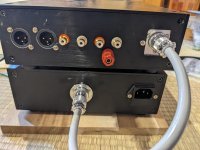
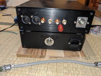
I assembled a SFF Windows 11 PC a few weeks ago for playing music and surfing the web. It only has one PCIE x16 slot and when I put the Pink Faun I2S bridge in that slot it is not recognized (yes the power was plugged in). The I2S bridge directions mention that it is to go in slot 2 so I suspect this has something to do with it not being recognized. I've email them for suggestions so I have to wait for a response.

In the mean time I noticed that the motherboard supports a PCIE riser that will turn a x16 slot to x8x8. There is an option to turn that on in the bios. I'm hoping that installing a riser and splitting the lanes will get it to recognize. I ordered a riser that will split into x8 and 2 x4 NVMe HD slots. Since Amazon had one in stock that would arrive in four days I decided to try that. There are x16 to x8x8 risers but the slots are rotated 90 degrees so I'll need and extension cable as well to mount the card properly. Below are the links to what I have. Has anyone come across this before and got it to work?
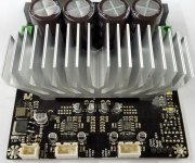

I2S bridge
https://www.pinkfaun.com/shop/bridg...tml#/521-additional_clock_for_i2s_bridge-tcxo

Motherboard
https://pg.asrock.com/mb/Intel/Z590 Phantom Gaming-ITXTB4/index.asp#Specification

PCIex16 to x8x4x4
https://www.amazon.com/dp/B0BN596WMN?psc=1&smid=A4IWNATC64MMF&ref_=chk_typ_imgToDp

Designing a small bluetooth boombox, here's where I've gotten so far, comments/criticism welcome

A little while ago I built a 2.1 boombox and it sorta inspired me to make a "version 2.0" that will be more compact but hopefully just as capable, using the lessons learned from the first one and some more research.

My goals are for something not too heavy to carry (probably already ****** this up with my subwoofer driver choice, I had no idea it would weigh 7.5LB till it showed up, oops),
Reasonable battery life, and compact - hopefully around 0.5 cubic feet total or roughly 30x30x15CM/12"x12"x6".


To power it, I got this 4.1 DSP amp: http://manual.likeyou888.asia:8000/EX401.html, supposedly 50w x4 + 100W for the sub. I'm open to changing this out if there's something not insanely expensive that will outperform it. And I plan on putting a bigger heatsink on it, and probably placing it somewhere that it'll get some sort of airflow cooling from the subwoofer.

To power that, I'm building a 4s5p 18650 lithium battery, I did a bigger version of this before for my first boombox (4s10p) and it was super overkill. I think this should give it easily all-day listening at 3/4 volume. I have yet to charge my 4s10P version after 2 weeks of listening to my other boombox an hour or two a day.

For drivers, I've got the following:
Tweeters:FSA544010-1800
Midrange: FSA524030-3800
Both of these are made by Eastech and were in a fantastic 2.1 computer speaker system: https://www.ixbt.com/multimedia/corsair2500.shtml (review with info). I had these around already and really like how they sounded on my PC. The enclosure corsair put them in was 1.5L sealed per side, so I figured I'd just copy that.

For the subwoofer, I chose the Epique E150HE and the plan is a 8L (+/-1L) ported enclosure with a 6.5CM diameter port 46CM long, which I think I'll try and incorporate into a handle or something since 46CM is pretty long, but that's what WinISD comes up with for that driver.
I was planning on making the enclosure on a 3D printer, but I might actually make it out of plywood and lexan instead, just because I've got some and I do wonder how durable a 3D printed enclosure would be.

Questions, comments, ideas are welcome! And remember, I'm new at this, so if it seems like I'm overlooking something obvious, well, I probably am, please point it out!

Resistors in signal path (Gridstopper R)

Hello good people,

I am wondering about a thing -
I have seen several examples of a medium capacitor connected in parallel with an expensive and good quality one in order to achieve better sound quality.
Can't I do the same with resistors?
If, for example, I connect an Amtrans and a Wishay Z-foil in parallel, I will in theory achieve the sound quality of both components.
Of course, both resistors must be the same value and twice the size of the desired one. Like 2K Amtrans AMRG parallel with 2K Wishay Z-foil = 1K Amtrans/Wishay as gridstop resistor.

I can't find any discussions on this topic.
Can you follow me and is there anyone here who has tried bypass resistors in this way or am I completely nuts?

Pft.
Henrik Vingborg

Help with charge controller for an electric boat based PA system

Hello all
I am getting very mixed up about selecting a controller. My loads are electric propulsion and audio amplifiers. Max load would be around 1.2kw total

Panel are 4x 12v 350w
Battery is a 12v 100AH LiFePO4
Power to the amp modules and electric motor controller will be delivered from the battery by using a 12v to 48v up DC-DC up converter rated 1.8kw

I would really appreciate some assistance in selecting an appropriate charge controller and if the item linked below is suitable for interim use. It's the 100A model in the listing
https://www.ebay.com.au/itm/226084981529

Saving up for a high end unit from this list linked below
https://www.outbackmarine.com.au/po...trollers/victron-smartsolar-mppt-controllers/

Ideally, on a good day, I would like to draw about 700w for the motor and no more than 30wrms for the amplifiers while cruising without draining the batteries. The project is logged here but in shambles regarding power up
https://www.diyaudio.com/community/...ofers-and-two-cats.416718/page-3#post-7784860


Thanks and regards
Randy

For Sale Pearl 3 clone build

I built 2 pearl3 for me and someone asked me to build but he cancelled.
I built with quality parts,Amtrans amcg caps,
I add Muses01 and Muses8920.
Quority cable and connectors.
For PSU(UDP3) I will buy 22V secondary Rcore transformer for other countries.
(Takes 1-2weeks for order)
Separate aluminium chaissis.
5mm Iron plate glued on lid.

500usd+shipping 100usd(some countries are expensive or difficult to ship)
PayPal(friend family option) or Revolut.

Attachments

  • PXL_20240829_035952855.jpg
    PXL_20240829_035952855.jpg
    301.1 KB · Views: 269
  • PXL_20240829_040150899.jpg
    PXL_20240829_040150899.jpg
    514.9 KB · Views: 280
  • PXL_20240829_040216249.jpg
    PXL_20240829_040216249.jpg
    519.8 KB · Views: 275
  • PXL_20240829_040051332.jpg
    PXL_20240829_040051332.jpg
    366.9 KB · Views: 263
  • PXL_20240829_040126409.jpg
    PXL_20240829_040126409.jpg
    558.9 KB · Views: 231

Chuffed, twin flare BR part 2

The bandsaw special, redraw
This will evolve a bit more as I get it ready for cutting. Here is what it looks like based in 16mm sheet material. The lines show panel buildup in some areas. At the port exit, the lines show 6x 48mm slices made up of 3x 16mm panel each plus a single 18mm slice in the centre. Braces are shown without cutout and this carving will happen with the driver cutout depth constrain

Pipe Sd had increased slightly to 50cm2 and depth is still 306mm. Mouth flare has increased to 500cm2

Vb 30L (+5.2L reserve ballast for driver chassis and space taken up by electronics and fill, total internal excluding port is 35.2L)
External width 340mm, depth 400mm, height 460

Port non flared section Sd 60 cm2, slot width 306mm, total port length including twin flares 439mm
Driver, any pro mobile subwoofer that fits a face. Currently configured for the DS18 ZXI12.4D running 1.2kwrms/2.8kw dynamic and tuned to 31.4Hz

Suggestions for a more well known driver 8 to 12" and capable of F3 33Hz and average 115dB potential that can work in 30L? Maybe
https://www.wagneronline.com.au/attachments/Audio-Speakers-PA/sbacoustics/SB34SWPL76-3-DV.pdf

The intention is to optimise a true BR rather than diverge into a line. This is the main problem with low Vas pro mobile subs. The ports end up like poor TLs due to aspect ratio. The original thread did result in a good-looking TL and TH when I optimised the long port

The graphs below are at 78.4v and 281g of polyfill in the Vb

Will she huff, puff or chuff?

1722294193349.png 1722270207971.png

1722295817698.png1722295698574.png
1722295997971.png 1722296158725.png

1722296232858.png 1722296303495.png

ALW Super Regulators - Are C5 & C7 needed

Sorry - I am rather late to the party with these regulators - I bought some a long time ago and only now have I got around to building a homebrew HiCap for my Naim NAC 72 pre-amp. Regaulators are working OK and i'm just dotting the i's and crossing the t's before installing everything into a case.

In the build documentation the BOM says not to fit C5 & C7 but the remaining documentation mentions their function and the circuit diagram clearly shows them. Does anyone have any thoughts on whether to add them or not? C5 is 100uf and decouples the emitter of the pass transistor to ground. The NAC 72 has a number of "daughter cards" each with 47uf decoupling capacitors. Should I eliminate C5 and keep the NAC 72 decoupling capacitors as-is or go with my gut feeling and install C5 and reduce the local decoupling in the NAC 72 to say 4.7uf film caps?

Can somebody justify my subjective opinion with math?

I've recently scrapped a Wharfedale DX2 sub (70w, 8" driver 15l sealed cab). I transferred the driver to a 24l ported cab.
Wow!
The ported cab uses a 28w amp for bass, yet it outperforms the original 70w DX2. An LFE improvement was expected + 2-3db for the port. The results give me pause. Maybe throwing more power at the problem isn't the best first option.

Can you guys look at amplifier boards/innards and say whether a circuit seems good, questionable or just downright bad?

I lack the knowledge unfortunately.

The first one is a John Shearne Phase 2 integrated, one of which I owned some 25 years ago and am contemplating to perhaps buy again if a good example turns up.

1726487490703.png

1726487665702.png


It looks like the firsst one may already had something changed but I can't be sure. Many thanks

DIY Sony VFETs OS2 Official thread

Attached is the document detailing the DIY Sony VFET OS2 output stages.

These are revisions of the previous efforts for the N channel 2SK82 and P channel 2SJ28 design but intended to accommodate people who have those VFET or other Sony VFET transistors, notably 2SK60 and 2SJ18 or even other power Fets in TO-3 packages, including Mosfets.

The biggest differences are in the current sources. Where the originals used constant current sources, for the P channel design we have a mu follower and for the N channel a novel variation. Both of these are constant current for DC, but can be adjusted to supply a percentage of the output current in support of the smaller VFET chips.

The diyAudio store will be making its announcement shortly with an initial stock of both output stage kits, which are compatible with original and new kits for front ends and power supply filters, especially Mark Johnson's efforts. I have been asked to assure you that there will be plenty to go around, no problems, and even if you don't have the VFETs you will be able to make Mosfet versions for TO-3 and also TO-247 plastic packages, so don't fret. Also the ever benevolent 6L6 has agreed to do build guides.

So here we go. Stay in line, no crowding....

:snail:

Attachments

Suggestions for DIY PP amp

A question for Planet10 and others:

One of my adult sons has shared some remorse about not building an amp with me. Well he's 32 this year and I told him it's not too late.... at least while I can still see and solder! I'm looking for a push-pull schematic that can drive more conventional speakers and does not break the bank on iron needed. I've built many 2 stage single ended amps, mostly using DHTs but I use/prefer high efficiency horns.

Please send any ideas my way!

Thanks,
Jim

WAW: SB23MFCL45 + CHN-50

Completed a design and build with SB Acoustics SB23MFCL45 and Markaudio CHN-50 as I wanted to do a WAW for some time now. Main goal is to push the limits in drivers, a (sub)woofer combined with a small FR driver for mids and highs.
1000026340.jpg


1000025126.jpg


Design considerations:
  • Separate cabinets for bass and midtweet to allow easier experimentation with different midtweet drivers. Additional benefit that it might prevent some colouration of the mid by bass frequencies.
  • Closed cabinet for woofer. It doesn't have to go very low (e.g. <30hz is less of a concern for me) so rather choose the benefits of a sealed cabinet. Ideally no DSP enhancements such as LT.
  • Active crossover using Minidsp SHD somewhere in 200hz-500hz range
  • Distance between drivers <1/4 wavelength
  • Midtweet at approx ear height
  • SB23MFCL45 since: it's ~8inch woofer, I want to use it rather high up for a (sub)woofer to have enough overlap with small FR (it has a good response till >500hz), and it can go low enough sealed without LT or other filters.
  • CHN-50 as I really like it as a midtweet. I have small children running around so don't dare to use an Alpair/MAOP 5😉. Potential to change this in future.

Design:
  • Sealed midtweet cabinet of 3.25l with rubber feet
  • Sealed bass cabinet with q of .6, 41l
  • Settled on 300hz crossover frequency using LR4 for now. Tried some other ones e.g. 450hz but 300 sounded more balanced to me.
  • Distance between driver centres is 20cm

Cabinet size and tuning frequency

Is there an optimum F3, port tuning frequency, for each specific cabinet size? For example 2 liter is 100 Hz, 3.5 liter is 85 Hz etc? Meaning you choose your F3 and then pick the appropriate size box?

For the Tang-Band W3-593SF Parts-Express recommends a 5.4 liter cabinet tuned to 75Hz. I have a 3.5 liter cabinet and a 7 liter cabinet. Do I want to tune the 3.5 cabinet lower F3 than it should or tune the 7 liter cabinet higher than it should? Another option is add some wood blocks inside the 7 liter to decrease the volume.

I do not understand why the W3-871S has a Vas of 1.66 liter and 0.29mH when the identical (except frame) W3-593SF has a Vas of 2.67 liters and .084mH?


Also I do not understand how this driver has a resonant frequency of 110 Hz but Parts-Express design it to 75Hz. Is not Fr the lowest a driver can go?


Perhaps there is some calculation or program for cabinet sized and F3 tuning frequency?

FREE Operation and Service Manual for HP1722B Oscilloscope

I have the Operation and Service Manual (with schematics) for an HP1722B Oscilloscope that I don't need.
Free to anyone that is willing to pay shipping from Colorado.
In pretty good shape, although the pages are loose from the binding. I assume someone pulled them out to scan or copy.
I think all the pages are there. They are in good shape and very readable.

PM me.
Terry

Wondering about calcs in SB 201 book

Hello everyone -
(this is a duplicate of a post in Introductions I was instructed to make)

I'm going through the calculations of the late Ray Alden's excellent Speaker Building 201 book and I'm scratching my head about some of the formulae.

Specifically, in several sections on page 73 and 74, the numerator for some inductor calculations are shown as Rt, which is also used to describe the nominal resistance of the tweeter, but here the context seems like it should be Rw, for the woofer.

Of course, in cases where the woofer and tweeter are 8 ohm units, the point is moot, but if one is substituting real-world value, this could affect the resulting calculated values.

Am I missing something here?

8" high efficiency midbass driver suggestions

I'm in search of a decent 8" midbass driver. Needs to do mid-90s dB/2.83v and handle the 300 - 900 hz range with ease, preferably 4 ohm impedance.

The main issue I'm running into looking for a suitable driver is sufficient xmax along with efficiency. The driver will need to handle some decent power without turning into mush with loud transients. Obviously it will need to be some sort of pro audio driver given the application. Low distortion is a must.

Drivers like the Audax PR170MO don't have enough xmax to play louder without using steeper HP filter slopes. Levels I expect are 110 dB peaks in the specified range.

My other favorite B&C 8NDL51 isn't quite efficient enough and isn't available in 4 ohms. The 8PS21 has the same issue.

The 8PE21 is efficient enough as an 8 ohm driver, but not enough xmax to deal with a 300 hz 2nd order HP at higher output levels.

I've toyed around with the idea of using 2 drivers, but this will result in weird vertical dispersion issues.

Any suggestions?

XSim4 program available

Hello,

I recently needed to use XSim functions for some circuit simulations (EQ for the MEMs Mic thread).. Code from the abandoned "XSim3D" program was edited and modified for that, and so XSim4 is born.
(XSim3D was abandoned because it was getting too complicated and clunky, buggy, and was losing the ease-of-use XSim was intended to have. And VituixCAD was already handling those 3D and directivity simulation features in a better approach.)

I took out the "3D" stuff, and left in the working Active EQ, Opamp, and Filter components, and (I hope) cleared up some obvious bugs left from XSim3D and (I also hope) kept the ease of use. There are some small changes you may see in the driver setup options. Also, the frequency range for XSim4 is extended to 1Hz to 100kHz which I needed for the microphone work. You probably won't need out to 100kHz, and probably won't have FRD or ZMA files of drivers that go out that far, but you can easily change the displayed range.

One issue that might come up with simulation up to 100kHz is that time domain displays (like impulse response, square wave response or step response) might get hairy from including the extrapolated data up to 100kHz. If this is an issue, you could add a filter block right after the Power Amplifier block to roll off above 20kHz. Or if I get time and there's any demand, I may add a button to roll off files that only have data to 20kHz.

Download XSim4 at:
https://www.libinst.com/FreeAppDownloads/XSim4Setup.exe

Standalone MM Phono Stage Project

All,

I just completed a magnetic phono preamplifier project. It is a relatively simple unit that uses all 6C45P Soviet designed tubes.

Photos of the unit are below.

Chassis Front.jpg


Chassis Rear.jpg


Chassis Parted.jpg


Inside.jpg


Schematics along with AC (in green) and DC (in red) node voltages are recorded below. This data was taken 20 minutes after unit was powered with a BK Precision 5491B 5000 count multimeter. Mains AC measurements were taken with respect to neutral. Heater AC measurements were taken with respect to the GRN and BRN wires. High-voltage AC measurements were taken across the YEL and WHT wires. All DC measurements were taken with respect to GND.

Power Supply DC Voltages Input Shorted.png


Phono DC Voltages Input Shorted.png


In summary:

1. All audio performance data was taken with a QA403 Audio Analyzer. The yellow line is the left channel, the red is the right. Photos of the test setup are below.

Setup 1.jpg

Setup 2.jpg


2. The unit was designed to take a -48dBV signal, off a moving magnet pickup, and amplify it to around 0dBV, at 1KhZ, with a 22k ohm resistive load on the output. See image 4 for a test tone on an unloaded output and image 5 for a loaded output.

3. THD, at 1kHz, ranges from 0.004% to 0.01% with no load, and 0.01% to 0.02%, with the 22k ohm load.

4. Unweighted, the signal to noise ratio ranges from 68dB to 71dB. With A-weighting, it is between 81dB and 83dB. Note that the testing was not done with great quality RCA cables, as I have none on hand. This explains the 60Hz spikes and harmonics present in the data. With better interconnects, I expect the signal to noise ratio to improve, along with the THD.

5. When RIAA weighting is applied to test tones across the audio band, there is 0.2dBV or less deviation between the tones. See picture 7.

Questions:

1. What do you all think of this unit, its construction, and the test results?

2. I only tested the unit. I have not yet listened to it. How do you think it will sound?

3. What RCA cables do you suggest I use? The ones I happen on seemingly pick up more hum that they should.

Thanks,
The TorroidDoughnut

Attachments

  • 1. No Power.png
    1. No Power.png
    97.4 KB · Views: 83
  • 2. Unit On - Inputs Not Shorted.png
    2. Unit On - Inputs Not Shorted.png
    102.3 KB · Views: 86
  • 3. Unit On - Inputs Shorted.png
    3. Unit On - Inputs Shorted.png
    105.2 KB · Views: 91
  • 4. Unit On - -48dB In No Load.png
    4. Unit On - -48dB In No Load.png
    123.9 KB · Views: 78
  • 5. Unit On - -48dB In Load 22k.png
    5. Unit On - -48dB In Load 22k.png
    121.8 KB · Views: 74
  • 5. Unit On - -48dB In No Load A Weighted.png
    5. Unit On - -48dB In No Load A Weighted.png
    119.1 KB · Views: 79
  • 6. Unit On - -48dB In 22k Load A Weighted - Copy.png
    6. Unit On - -48dB In 22k Load A Weighted - Copy.png
    122.4 KB · Views: 85
  • 7. Unit On - -48dB In 22k Load RIAA Weighted.png
    7. Unit On - -48dB In 22k Load RIAA Weighted.png
    86.7 KB · Views: 96

Greetings from British Columbia.

I've loved audio since I was a teenager back when dinosaurs roamed the earth and a coke was 10 cents. Built a Dynaco ST-70 and a PAS-3 with the money my wife's parents gave us when we got married. Wish I still had them! Built a pair of Altec Voice of the Theatres, painted them black and listened to them near field in the living room. Good times! Managed to score a pair of Klipschorns forty odd years ago and I'm still listening to them to this day. Modded them over the years and finally sprung for the Greg Volti upgrade and new Crites woofers. They're at a different level now. The honk is gone and they don't just sound good in the next room. I've restored some pieces over the years such as a Conrad Johnson integrated. I've started loving my record collection all over again and still buy the odd new release. I am thinking of building an Elekit TU-8900. Hoping I may find some advice and tips. Those old K-Horns deserve a few less watts!

The quest for ATH generated (R-OSSE) free standing round/octagonal MEH

My 9sided conical MEH was a successful test of making petal construction on a CNC from flat boards. Unterminated conical horn has some issues - although I measured much less than in simulations.

1. there is ripple in the upper band FR including a quite serious notch slightly above 1.5 kHz
2. there is some narrowing in the mid band that allows only optimization by EQ on a single axis

The issues can be equalized by using comprimised setting to inaudibility or more precisely, not to annoy me while listening.

However knowing they are there forces me to try to do better next time.

Here comes the great free ATH tool by mabat. First, I tried to generate a roundover to add to the existing horn - which reduced the issues in simulations quite considerably, but I could not really get rid of the narrowing, only reduce it. The R-OSSE profile is relatively flat, so iz would allow the following construction in three parts:

1. part - throat adapter with a flange. To improve the directivity and FR on the high end, this time, 1" driver will be used. It must allow 1 kHz crossover at home listening volumes - I measured maximum around 85 dB, A weighted, 100 ms interval, which is already pretty loud. I will allow for 20 dB headroom, which still gives me less than 1 W for a typical 1" driver. It should have low resonance and a short distance between the acoustic center and the front. There is a pretty good choice these days. The adapter will convert the exit angle of the driver and the circular cross section to an octagon.

2. part - flat on the outside, curved on the inside, 8 parts. Mids (4 x 3FE22 most probably) and lows (2x12") will need to fit this part. That is a challenge, since a well simulating horn roundover takes a lot of space. 2x10 or even 4x8" might be needed, otherwise the horn gets too big

3. part - the roundover - to br around 50 mm thick with a flat backside. Mouth diameter will be slightly below 1 meter.

The 3D construction will need more material and would weigh too much, so there will be layered construction and material from outside will be removed where possible allowing to fit damping material as well.

The mids will be placed on the "diagonals" flat parts, the lows on the sides and their enclosures will also serve as a stand.

I have finally found a pretty good profile, generated by ATH. I need to modify the ABEC profile to see how much the performance would be degraded by different back of the waveguide (flat back of the roundover and some mockup of the driver back covers) only as the worst case im circsym.

Another challenge for this construction will be that only a single profile will be used to curve the octagonal walls, so there will still be a difference between round and octagonal. Full 3D round inside may be also possible with the tools at my disposal, so that will be investigated as well.

The quest has been fun so far, over the two rectangular and one round prototype, this one will be most probably very close to the "end game" MEH - unless I find out that full 3D sliced construction is really necessary (like Joseph Crowe's Nighthawk series).

The progress will be documented here, please wish me luck and any input and constructive criticism is welcome🙂

Do foam surrounds still rot?

In the beginning, Kellogg and Rice invented the electrodynamic loudspeaker.
Shortly after that, people starting worrying about foam surrounds rotting out.
OK more seriously, is this a thing with new speakers any more? I recall a nice fellow Neal Baitcher from Nu-Way speaker component company working on that and saying it would be a thing of the past. I still hear about foam rotting out: is that only ancient speakers? Or do newer foam surrounds still rot eventually.

Passive reflex radiator nearfield measurements

Folks, first of all I'm not a fan of reflex loaded woofers, but lately I've noticed invasion of PRs in hifi-speakers, like Amphion Two18 and many 2-ways with Purifi woofer. Subwoofers are very simple cases because of low-pass at 80-120Hz.

Small box and low tuned passive radiator is theoretically easier to make than a reflex port. Many easy online calculators can give port dimensions so most DIYers use them. The port easily chuffs and leaks midrange frequencies in opposite polarity, making sounds that can be heard and measured.

Passive radiator(s) are easy to fit on the backside of the box and they don't eat box volume. Listening impressions are good, but I have failed to find nearfield measurements that can show obvious resonances and "leakage" of midrange. The PR has wide membrane, so that's strange regarding pursuit for rigid non-resonating encloseres...

Below my measurements of my subwoofer running without xo, Peerless XLS10 and respective PR. Drivers are side-by side, so nearfield measurement of the PR is not "clean". I don't have now time to make a test box with opposing placement, so I ask help from fellow diyers. I have taken also some distortion plots with sine at tuning freq, but I couldn't find them now.

xls10 box stuffed spl combined.jpg xls10 nearfiel act pass 20ms 124.jpg xls10 nearfiel act pass 500ms 124.jpg

Power LED for BOSOZ supply

I finally rebuilt my BOSOZ power supply ....dual mono with 60 volt rails. Essentially the BOSOZ articles circuit. Seems to work fine, need to use a scope tommorow.
I forgot to put a on/off LED on the front panel and now Im wondering the best way to implement the LED. Im not sure if a voltage coverter/series resistor tapped off on only one rail is the way to go.
This dumb *** is very open to suggestion
Thanks


IMG_7461sm.jpg

hybrid Karlson ML-TL

hello everyone .
I want to build a Karlson K12 variant . what I want to change compared to the original project is the rear chamber .
no longer a bass-reflex chamber but an ML-TL .
I thought of building a cardboard model so you can understand better .
as you can see from the photos the chamber is composed of 5 sections that have different shapes and sizes .
the one corresponding to the speaker has a triangular shape and the front side has a slope of 60 degrees .
the chamber continues below with a narrowing ,
it passes to a linear section that at the bottom divides into two other lateral sections .
the area of the central section is equivalent to the sum of the lateral ones .
it continues upwards with a narrowing then ends at the end with two narrow and long openings placed vertically on the sides of the container .
excluding the final part, all the other sections have a larger area than the SD parameter of the 12" driver.
this configuration allows you to keep the dimensions of the original K12 container unchanged
(width and depth) the only dimension that changes is the height.
however there is a substantial change in shape when you move from one section to another
I wonder if there is a similarity with what is described in the link below:
http://www.organstops.org/_apps/HaskellBasses.html
some time ago I built a K12 prototype, its front chamber has the classic exponential opening but
the one built by me has a triangular shape so it is different from the original one (you can't see it in the photos).
I intend to reuse the same front chamber for the new project,
that's why I can place the openings on the sides of the container, as has already been done previously.
I don't know what the behavior could be so before building the container and test it
with a speaker that I have to buy (I already have a 12" driver but I don't know its TS parameters)
I would like to know your opinion.
if this container has what it takes to work I ask you for advice on buying a 12" speaker
(I don't know if it is better to buy a definitive driver that can cost even €300 or instead buy a very cheap driver for the sole purpose of experimenting).
I don't know which one to choose.
thanks.

Attachments

  • IMG20240824225121.jpg
    IMG20240824225121.jpg
    333.6 KB · Views: 124
  • IMG20240824230318.jpg
    IMG20240824230318.jpg
    363.8 KB · Views: 127
  • IMG20240824230838.jpg
    IMG20240824230838.jpg
    342.5 KB · Views: 133
  • IMG20240824231254.jpg
    IMG20240824231254.jpg
    329.7 KB · Views: 124
  • IMG20240825163959.jpg
    IMG20240825163959.jpg
    357.1 KB · Views: 124

Hybrid crossover questions

Hello all. I've got a slightly unusual situation but it's not too complicated, and I'd like to ask for some input about a passive crossover I'm going to need. Here's the details:

It's a horn-on-box system, right now the horn is a Le Cleac'h (Martin Seddon Azura) 425, playing from 600hz up. The crossover is an active Sublime 241. Of course, this requires two amps, and the horn is driven by a triode strapped EL34 PP tubie and I love the sound. The 15" woofers are driven by E3 class D diy, also great for the application. Here's where it gets slightly interesting...
I'm going to add a little Le Cleac'h to take up the "tweeter" duties, and will cross somewhere between 2k and 4k depending on how the impedances play out. But I don't want a third amp, so I'm going to divide the two horns with a passive network. I want to keep it as simple as possible, and if things measure smoothly enough I'd like to use 2nd order, but confused about whether to use Butterworth or LR. If I read the crossover chapter of LDC one more time I think I'll hemorrhage, I understand it for the most part but it's still not clear what the differences would be except on the screen. Phase isn't such a big deal because the horns are independent on the z axis so offset is easy to adjust.
Does anyone have any advice on this?
Thank you,
Bryan

Hello all!

I'd like to introduce myself shortly. I've been in the business since my youth, learnt, built and attended hobby club and competitions since I was like 8 or 9. The love for electronics is still in my heart (strangely enough since its also my daytime job most of the time, hehe) and as former musician, I like audio equipment in particular. Like, what's better than good sounding rig, right? I started studying and restoring turntables some 12 years ago quite extensively and then added amps and receivers after some year or two. Now after years of restoring vintage amps from Marantz, Kenwood, Toshiba, ReVox, Yamaha and so on I want to try building something by myself once again. Preferably with tubes. Preferably an instrument amp at first. I'm always open to crazy ideas, unusual paths and strange solutions, as well to straightforward, clean and logical ones. I'd like to find inspiration here and I will be pleased if my few cents now and then will be appreciated by someone else. Thanks for add.
  • Like
Reactions: Johno

Hello all

Hi,
My name is Bobby and i am from Macedonia.
I love music and sound systems have always been an interest for me. I have built amplifiers, speakers and many musical instruments.
My knowledge of electronics is limited and I want to learn.
Thank you for accepting me to your community and I am looking forward to your assistance. I would love to contribute to topics where I can help empower others.

For Sale 3e Audio TPA3251/55 & PSU Cheap or they go in the bin

Price drop
AMP Balanced/unbalanced TPA3251 & TPA3255 AUD45.00
PSU AUD40.00.

Yes I will post anywhere AuPost delivers and yes I will charge insurance and the cost of the box and there are no returns.

Photos for illustrative purposes.

I have sold some, so check out what I have left

Attachments

  • 200W 36V-6A Quasi-Resonant PSU For TPA3251-003.jpg
    200W 36V-6A Quasi-Resonant PSU For TPA3251-003.jpg
    243.2 KB · Views: 87
  • 333-125-279-929-02.jpg
    333-125-279-929-02.jpg
    201.5 KB · Views: 83

MG100DFX stuck in standby

Jamlot

Member​

Joined 2024

I recently bought a Marshall MG 100 DFX, it was going cheap and sold as not working. I don't know much about electronics but was hoping for an easy repair, fuse, transformer etc. After watching YouTube videos and reading online forums I've been able to conclude that the amp is stuck in standby. I've replaced all of the standby cct and the power chip but it's still stuck in standby.
Looking at the data sheet for the power chip it needs min 3.5v but I'm only getting 0.68
If I put a short between the regulated 5v and the standby cct input the amp works, so I just need to fix the standby cct.
I've made a drawing of the voltages I'm getting so I'll try uploading it
Any help would be greatly appreciated
Thanks

Attachments

DC-DC voltage reduction/regulation circuit

In my quest to repurpose an MCS chassis, I would like to not have to buy a transformer. So I have available to me the existing 60Vac output, which I can feed into an existing rectifier board giving me +/- 40V DC.

I would like to re-regulate? the power down to +/- 18-24V.

I had thought that this would be an easy search, but I must not be typing in the correct terms. Ideally, this will be feeding an MM phono stage.

Given that this would seem to be a way to further separate the transformer from the system, I thought these things would be falling off trees. Am I missing something obvious here? Or, is this a fools errand to try to use the stuff I have?

The +/- 40 supply rails each have 3x12000 uf capacitors. Not sure how much capacitance would be needed after the voltage drop, but maybe some of these capacitors could be moved to the reduced/regulated circuit?

In an ideal world, these would be small enough that i could use this to individually feed the phono preamp on a fully separate circuit, and adjustable between +/-12 to 30V DC.

Clon JC2

hello again I put another preamp that is pretty good, the price is something more than the C-3850, but it is still cheap, has good measures something offset 40mv, but once it is with signal there is no noise and much more open sound than the C-3850, I like it more I have tried with several OPA and there is little difference, so I put screenshots, greetings.
2.jpeg
jrc5534 vs muse.jpeg

Muse 03 Yellow Op07 Pink 300khz
NE5534 OP07.jpeg
WhatsApp Image 2024-08-24 at 12.16.54.jpeg

NE5534 vs OP07 300khz
WhatsApp Image 2024-08-24 at 12.19.26.jpeg
WhatsApp Image 2024-08-24 at 12.16.54.jpeg

NE5534 vs Muse 03 300khz
WhatsApp Image 2024-08-24 at 12.20.47.jpeg

as you can see at 100khz there is almost no difference.
Snap_2024.08.26_19h41m59s_002.jpg
Snap_2024.08.26_19h44m38s_003.jpg

be careful with the first one, the one with the potentiometer has a lot of distortion, I'm going to give it to a friend.

Attachments

  • jrc5534 vs muse.jpeg
    jrc5534 vs muse.jpeg
    284.1 KB · Views: 101
  • Like
Reactions: Kleinhorn

For Sale Tamura F-475 set

Selling, in like new condition:

2x Tamura F-475 OPT : 5K, 45ma / 16,8, 4 ohm 7.5W
1x Tamura A-395 choke: 10H, 120ma

Ideal set for a stereo 45, 46, EL84,...amp

SOLD

Attachments

  • tempImagecn3UVo.gif
    tempImagecn3UVo.gif
    1.7 MB · Views: 152
  • tempImageipCN8L.gif
    tempImageipCN8L.gif
    1.8 MB · Views: 107
  • tempImage7l8dug.gif
    tempImage7l8dug.gif
    1.7 MB · Views: 103
  • tempImageMAM5jk.gif
    tempImageMAM5jk.gif
    1.6 MB · Views: 113
  • tempImage8SYAVG.gif
    tempImage8SYAVG.gif
    1.5 MB · Views: 133

Fieldcoil + K-tube

Good morning DIYaudio-forum,

for demo-purposes i made a transportable loudspeakersystem out of a Supravox 285GMF (in an open baffle) and a FaitalPro HF10AK (combined with an original "The Tube" K-tube).
Surprising deep reaching and snappy bass, good soundstage and very usefull sensitivity. I used it at several national audio-gatherings (pre-Corona times....) but also several times at the European Triode festival where it was coupled to small and large amplifiers in big rooms.
Some pictures included including an ETF-picture where it was hooked to a GM-100 amp an a large room: great results.

It is that succesfull that it lead our audio-group started to deepdive into those K-tubes.

Regards,
Reinout

Attachments

  • DSCN0342.JPG
    DSCN0342.JPG
    450.1 KB · Views: 1,015
  • DSCN0242.JPG
    DSCN0242.JPG
    614.6 KB · Views: 983
  • DSCN0356.JPG
    DSCN0356.JPG
    358.4 KB · Views: 1,013
  • DSCN0526.JPG
    DSCN0526.JPG
    517.8 KB · Views: 1,006
  • DSCN0529.JPG
    DSCN0529.JPG
    351.2 KB · Views: 970
  • DSCN0534.JPG
    DSCN0534.JPG
    408.8 KB · Views: 592
  • DSCN0535.JPG
    DSCN0535.JPG
    482.5 KB · Views: 521
  • DSCN1800.JPG
    DSCN1800.JPG
    188.4 KB · Views: 558
  • DSCN1911.JPG
    DSCN1911.JPG
    451.4 KB · Views: 603
  • P44.jpg
    P44.jpg
    315.7 KB · Views: 629

For Sale Satori MR13P-08 and SBA741 crossover

For sale a pair of Satori mr13p-8 high end midrange drivers and a pair of troels gravesen's sba 741 crossover.

The satori midranges are among the best midrange drivers available.


The crossover and speakers were build before the project became closed and therefore the parts are jantzen but not superior caps or the foil coils as the kit now sells for Jantzen.

Parts are as listed:

Tweeter section
0.7mm air coil jantzen
standard jantzen cap

Midrange
1.4mm air coil jantzen
standard jantzen cap
Crosscap jantzen caps

Woofer
1.4mm cored coil jantzen
elecap paired with a crosscap

All the resistors are superes or mox (one ore two resistors are slightly changed due to personal preferances)

The tank cap and resistor for the woofer is not available, since the kit was the same sounding with and without it and i didnt want the signal to go through useless parts.

Price is 350 euros
Shipping and Paypal fees are not included

Attachments

  • 368078886_716541756609406_2681342159095319371_n.jpg
    368078886_716541756609406_2681342159095319371_n.jpg
    189.3 KB · Views: 155
  • 387415917_248927671175101_5818110872000581731_n.jpg
    387415917_248927671175101_5818110872000581731_n.jpg
    153.8 KB · Views: 146
  • 367373258_6989031097829045_2741049330268528771_n.jpg
    367373258_6989031097829045_2741049330268528771_n.jpg
    168.6 KB · Views: 134
  • 387468212_1628956694262562_2180446265799283385_n.jpg
    387468212_1628956694262562_2180446265799283385_n.jpg
    107.7 KB · Views: 144
  • 380364660_322778637124587_2240839588418056348_n.jpg
    380364660_322778637124587_2240839588418056348_n.jpg
    90.3 KB · Views: 141
  • 380506142_304564002388269_704513928150811421_n.jpg
    380506142_304564002388269_704513928150811421_n.jpg
    294.4 KB · Views: 143
  • 385526600_336168512433289_2126271048896630776_n (1).jpg
    385526600_336168512433289_2126271048896630776_n (1).jpg
    332.1 KB · Views: 133
  • 385526600_336168512433289_2126271048896630776_n.jpg
    385526600_336168512433289_2126271048896630776_n.jpg
    332.1 KB · Views: 126
  • 380449664_208819528908217_5623654118479018835_n.jpg
    380449664_208819528908217_5623654118479018835_n.jpg
    203.2 KB · Views: 137
  • 380320561_980582279702963_2015732836291495928_n.jpg
    380320561_980582279702963_2015732836291495928_n.jpg
    240.8 KB · Views: 148

B&K ST-140 circuit board upgrade ideas

I have been working on making a drop in replacement PCB for the old B&K ST-140 amplifiers for several months now, and I after several revisions I have got a decent sounding amplifier. I would like someone to look over my work and give me ideas for improvements. I would like anything from mechanical ideas to circuit design layout.

I just recently bought several amplifiers to compare to my upgraded B&k amplifier. I bought a KST-150 and a topping LA 90. Both of these are supposed to be high performance amplifiers for the money and to my surprise the B&K amplifier blew the doors off both of these amplifiers as far as musicality and emotional engagement.

I am currently trying to order a Quant QA403 audio analyzer to do distortion and other testing on my diy projects but they are currently back ordered.

I am using the original power supply but with new kemit 20,000 uf caps. So 40,000uf total.

I'm getting about +63 and -63 VDC on the rails.

Please feel free to give me any suggestions I'm all ears.

Screenshot_20230510-112754.png

Attachments

  • B&K AMP.pdf
    B&K AMP.pdf
    24.9 KB · Views: 182
  • B&K PCB.jpg
    B&K PCB.jpg
    66.9 KB · Views: 221
  • B&K PCB 2.jpg
    B&K PCB 2.jpg
    46.9 KB · Views: 221
  • PXL_20230228_000446965.jpg
    PXL_20230228_000446965.jpg
    521.2 KB · Views: 235
  • FLIR_20230501_081000_826.jpg
    FLIR_20230501_081000_826.jpg
    435.9 KB · Views: 200

Considering the TI3255 in mono mode for a ripole OB subwoofer.

I am thinking of using a TI3255 in PBTL mono mode for a ripole / SLOB design. SLOB design consists of 2 Hertz 12" uno S300 S4 drivers.

Assume that the most likely thing is to parallel connect the drivers to get 2 Ohm on the amplifier? A bit unsure if the TI3255 has the possibility to drive this configuration? Is it correct to configure in PBTL mode or would it be more appropriate in 2.0 BTL? And last but not least, one TI3255 is enough, or do you need 2 pieces?

Super Triode Single Ended Amp

This design is taken from TubeCad. I ended up using a single Exicon TO-264 mated to a JJ 6922. The cathode / gate voltage’s matched up nicely. Regulated power supply for the Mosfet. Voltage Multiplier for the B+. High Freq Inductor from Hammond. I will post measurements in the near future. I am excited it didn’t explode upon power up. Current stabilizes ~ 7 seconds. 8 watts @ 8/4 ohms.

Dwight

07D8FDD2-222C-4D73-9F37-9BD344CE615A.jpeg

882F7E70-C502-4B7C-861D-1840895E1863.jpeg


75132E75-9EC0-402F-B297-A99F49DDF84B.jpeg


0EB1C64E-9882-4975-B3B6-7383261F438A.jpeg


1C2B9203-6889-4AF6-9BC5-B4D3EFF70371.jpeg

Grundig 903 - CDM 4/16 transport - Noisy eye-pattern / skipping

I’m currently working on a Grundig CD903 CD player. It’s a player with a CDM 4/16 transport and a TDA1541A DAC. The 903 is an almost exact copy of the Grundig CD 8400MKII which I also own so I can compare measurements between both players. The only difference is the display, the 903 has a VFD.

I bought this player as faulty from a “vintage audio shop” They claimed it was faulty and that they wanted to repair it but it wasn’t worth repairing it. I asked if they made any changes because I hate to work on equipment with partial repairs. “No, it’s all original” unfortunately they lied about that part.

After opening the CD player I could see some electrolytics caps were removed by cutting the legs on the topside of the PCB and new caps were soldered to the remaining pieces of the cut legs. After removing the main PCB I noticed that the newly tagged on caps made the solder connections on the underside of the PCB come loose.

What were the original symptoms:

  • Up on the first power up the player I noticed that the main fuse (160mA) was blown. After changing the fuse and powering up the player the display came up, the fuse stayed intact.
  • Most of the times the CD wouldn’t read a TOC and the swing arm would violently hit the end of it’s range with a loud “cloink” sound. Sometimes it started reading the TOC but wouldn’t play, again violently hitting the end of its range.

What did I do at first:

  • Changed most of the axial electrolytic caps and some of the others. All others measure fine.
  • Checked rail voltages and compared the ripple on them with my CD 8400MKII, funny thing is that the ripple on the working and fully recapped 8400MKII on some rails is much higher than the CD903. The CD903 does however have some extra electrolytics on the power rails as it has extra voltages for the VFD. I haven't checked yet if they might be of any influence. As the 903 has less ripple then the 8400 I expect this shouldn't be the cause of my problem.

What are the current symptoms:

  • The player works and sounds fine but skips pretty fast and the BIAS voltage is very unstable and it’s pretty much impossible to adjust it correctly. At the start of a CD I’m able to turn it up to around 350mV, skipping to the end of the CD the voltage is very unstable and differs between 300mV and 1600mV!
  • The eye-pattern has a lot of noise on it. This disappears when I turn up the laser voltage to around 70mV, which is of course no solution. I tried measuring the frequency of the noise and it is somewhere between 15.5 – 17.7 MHz
  • When it is playing tracks near the end of the CD and I press the stop button the swing-arm still hits the end of its range with a soft "cloink'", however a less violent then it originally did.
  • Sometimes, it appears pretty randomly, the main fuse blows. I can't reproduce when but it might be related to powering on after the swing-arm has hit the end of its range.

What did I do to solve these last problems:

  • Swapped the laser / swingarm from a CDM4/19 transport, this doesn’t make any difference.
  • Changed the clamp springs for new ones, lubed the clamp.
  • Checked the power usage of the spindle motor, the spindle motor that is currently in the transport uses 26mA when a voltage of 3 volts is applied. I compared it to several other spindle motors and the best running only uses 20mA at 3 volts, but others use up to 35mA while running fine. So I don't think the spindle motor is the cause.

Anybody suggestions on where to start? My knowledge on CD players is limited and I found some topics (like this one) with partially the same problems but they don’t show the solution. Somehow I should be able to see tracking errors but it isn't clear to me how to do this.

The included pictures show the noise and my attempt to measure the frequency of the noise.

IMG_3648.jpgIMG_3651.jpg

HH VX-150 Lower Bias, Less Disortion

I have a HH VX-150 that I've finally finished cleaning up and refurbishing. A little while back I removed the VGA daughter boards as that was causing significant distortion.

I have been experimenting... I removed the input DC caps C1, C2, C7, and C8 and added links in their place. I also removed C1 and C12 on the drive board and wire linked it. I increased the DC caps C3 and C14 in the feedback path to a silly 820uf as that is what I had lying around.

After that the DC increased and settled to around 40mV so not too bad. (My input source is a very very low DC offset)

The most interesting thing was the bias. Lowering the bias adjusting pots VR3 and 6 lowered distortion. (I measured the distortion at 30Khz at 10mv in a 4ohm load to get a good picture of crossover distortion)

I measured current draw from mains and voltage between gate pins + and -. it was originally 800mv between these points. (I believe the VX450 specifies 800mv). The distortion measured 1.2% (at the above paragraph method of measuring). Lowering to the lowest possible on the pots this decreased down to 0.8%! Mains current draw is now 80mA

500mV @ 1 kHz distortion was 0.0035% not bad at all.

Top end sounds much better after lower bias.

The only issue is DC offset jumps around upto 2V after swirch off! That will cause pops and clicks and risk to compression drivers! DC caps on the output would sort that out.

Attachments

Audio Research CA-50 input and Driver tube biasing

Hi there, hoping someone can help me. I have an Audio Research CA-50 amplifier and want to check it out properly, put all new tubes in and check the biasing. I have the instructions on the output tube biasing but cannot find anything on input and driver tubes. I have seen the great VT100 input bias video and found a number of old threads that refer to the need to bias the 6922's correctly, unfortunatley the documents linked to in those threads are no longer on line. So does anyone have instructions they could share on how to set up RV1 and RV2 correctly. They may be fine on my amp but without the information as to what they should be set to I cannot tell.


Many thanks

Simon

Nakamichi PA7 vs PA7II

Hello everyone, I need some advice from you.
I found two different versions of the Nakamichi PA7 and PA7 II. They would be designed to fly a pair of Infinity Kappa 8. Which would be the preferred one between the two? Do you have any advice? What should I pay attention to to verify that what I am buying is in good condition and that it is not necessary to proceed with an overhaul?
Thanks for all your help

Atoll IN80 broken

Hello all,

I purchased an Atoll IN80 three months ago, and have been using it with a pair of B&W 706 S3 so far, until yesterday when the amp suddenly died. It blew F2 which I replaced, and then it blew F3, and kept blowing it, while keeping the initially replaced F2 intact. (Did it twice only, hopefully I haven’t blown anything else). From the four LED only two remain on (from top to bottom: on, off, on, off).

From what I’ve been reading so far, the amp looks like to be hypersensitive to overheating and not “suited” for long periods of listening (I’ve been running it for a whole bunch of hours, almost everyday, my wife and I almost took “shifts” on it, lol).

Since I already opened it, and previously installed the phono stage myself, maybe the warranty won’t cover it (not really sure here)

Do you any of you have a schematic and a basic troubleshooting guide, or values to be attained at certain components? And if anyone have experienced any similar issues and to what it might lead (maybe a shorted amp stage), I’d super grateful.

Thanks,

Ark

Help with Sanyo Plus 55 tuner

Let me start by saying that I was a CET in the 70s but have not worked on a tuner since then. I have a scope, millivolt meter, DVM and function generator, but not a sweep generator. I have had this Sanyo Plus 55 receiver for 5 years, I made discreet replacements for the STK Darlington packs, and mainly keep it for the tuner. The tuner has gotten to the point that it will not pick up anything on FM unless the stereo muting is on and even then the reception is poor. It used to be quite good. I hooked up another receiver to the antenna and it worked great.
I checked the voltages on IC201 (LA1231N) FM muting chip, all except 13 and 16 are correct. 13 is 0.131vdc and 16 is 0.154vdc. I pulled C210/C212/C330 and they are fine. The voltages on IC301 are correct. I wonder if this chip is bad or is there a likely culprit I should be looking at?
Thanks


schematic.jpg
IC201.jpg

Neurochrome Modulus-686 (dual mono)

I'm a serial amp builder, and I assembled my dual mono Modulus-686 a few years back. It's an impressive beast, used off and on in various systems. With the many amps that I'm compelled to build, it's been sitting idle too much of the time. So, I've decided it needs a new owner who appreciates its many strengths.

Component list:
Some pictures:

11-CompleteInside.jpg


12-OutsideBack.jpg


14-OutsideElevatedFront.jpg


The total parts cost was CDN$3300, and I'm letting this go for just CDN$2200. (If you're in the States, USD$1600.) That's heavily discounted, and saves you the trouble and time to build it.

It's a heavy beast, so shipping costs will probably add another $200-300, depending on where you are. I'm willing to deliver it in southwestern Ontario, between Toronto and Windsor. Let me know if you're interested.

speaker driver material sound "timber"(+magnet types "timber" effect)

hi all 🙂
A little background...I come from a background of room acoustics and resonant acoustics, built electric guitars and pickups! + sound engineer and some experience in building active studio speakers

I would be very happy to hear from your experience on a subject that is very interesting to me and I probably don't understand it enough

In the question I am currently isolating all the other variables and referring only to the material from which the membrane is constructed(No need to explain to me that there are many other variables and it depends😅)

When I look at speakers from different companies and of course hear some of them, I feel that there are indeed features in terms of sound texture that are common to similar materials even when the speaker and the company are essentially different!( timber=tone color or tone quality )

for example:
Scanspeak Ellipticor (textile with extremely powerful neodymium magnet)
kef aluminum drivers
Accuton Ceramic Cone
Purifi proprietary fibre mix
tpcd
Diamond
Beryllium


In addition, the very combination with a different type of magnet affects the texture of the sound
good example is:
Satori TW29B-B Beryllium Dome Tweeter with[/B] Ferrite Magnet
vs
Satori TW29BN-B Beryllium Dome Tweeter Neodymium Magnet

Actually, what I'm trying to ask is how you look at the matter...when I try to design a speaker, my feeling is that the material from which the speaker drivers is built actually affects the basic nature! of the resulting sound, and therefore how do you combine different materials whose basic "nature" is different?

For Sale Pair of Lundahl Amorphous Output Transformers LL1623AM 80mA

I dissasembled the amps described here for a different project:

https://www.diyaudio.com/community/threads/my-experience-building-a-drd-d3a-300b-amp.61776/

I'll be selling different parts of these amps.

Here I'm selling a pair of Lundahl Amorphous Output Transformers LL1623AM 80mA complete with custom metal shield covers.

Price is 600 Euros + Shipping of your choice.

Attachments

  • DSC05005 s.jpg
    DSC05005 s.jpg
    40.2 KB · Views: 73
  • DSC05073 s.jpg
    DSC05073 s.jpg
    115.2 KB · Views: 75
  • DSC05074 s.jpg
    DSC05074 s.jpg
    41.1 KB · Views: 78

For Sale Pair of amorphous C-core TRIBUTE anode chokes

I dissasembled the amps described here for a different project:

https://www.diyaudio.com/community/threads/my-experience-building-a-drd-d3a-300b-amp.61776/

I'll be selling different parts of the amps.

Here I'm selling a pair of amorphous C-core anode chokes from Tribute. 75H-15mA.

This is the best that money can buy. Sadly Pieter from Tribute is not selling his products anymore to anyone but OEMs.

Price is 500 Euros + shipping of your choice from Spain.

Attachments

  • DSC04995 s.jpg
    DSC04995 s.jpg
    99.6 KB · Views: 84
  • DSC04997 s.jpg
    DSC04997 s.jpg
    214.7 KB · Views: 80
  • DSC05069 s.jpg
    DSC05069 s.jpg
    71.6 KB · Views: 72

amplifier CAYIN 860

  • Have a good time, everyone, help me figure it out.I have a CAYIN 860 amplifier with 12ax7,12au7,6n6 and four ct88 lamps in it,in the manual that I have it says that the lamps should stand 12ax7,12au7,6cg7 and 4pcs ct88,who can explain to me and who can have a circuit with a 6cg7 lamp,I will be very grateful.


  • https://translate.yandex.ru/dictionary/Английский-Русский/'

How good are our DIY units compared to off the shelf stuff?

I was pondering this the other day: "How good are our what we build compared to what the giants build?"

There is clearly a wide range of talent here. With me being right smack at at the bottom and I'm sure some titans of DIY right up there at the top.

Having myself only heard a couple of actually high end units in my life (one was a $30k system and one was $110k) I am definitely not the best to answer this posed question. I also listened to those systems many years ago. Long before I ever built one.

I was watching the highlights reel on the High End Munich show and saw, to my amazement, that most of the featured units use the same drivers that are available to me. I see Peerless woofers, Seas Mids, etc. I did see quite a few custom drivers which I am sure are made bespoke for those builds.

Are we fooling ourselves that our builds are anywhere near the polished unit of these are they just doing the exact same thing in an incredibly fancy box (in this case, enclosure)?

Let me know you thoughts on the topic and especially let me know if you've listened to a DIY right next to a high end off the shelf unit.

For Sale Tamura 46 drives 45/46 set

Selling a turnkey set to build, for example, a no holds barred 46/47 drives 45/46 SE tube amp.
This builds an LCLC PSU, with driver decoupling by an additional LC. Signal circuit all transformer coupled with an input transformer, interstage and output transformer.

Set contains:

1x PC-3004 power transformer
2x A-4004 10H 250 ma chokes
2x A-394 30H 40ma chokes

2x TD-2 600-10k input transformer
2x A-342 5k:5k 30ma interstage transformer
2x F-2004 5K:8-16 100ma 8W output transformers

All transformers by Tamura

Asking 2600€ for the set

All transformer are in excellent condition and will ship worldwide
(if you pull my arm long enough, i might build the amp for you...)

Attachments

  • tempImager92ykm.gif
    tempImager92ykm.gif
    1.5 MB · Views: 87
  • tempImageOLbrpH.gif
    tempImageOLbrpH.gif
    1.6 MB · Views: 86
  • tempImageLdNBIl.gif
    tempImageLdNBIl.gif
    1.4 MB · Views: 76
  • tempImageV71HbW.gif
    tempImageV71HbW.gif
    1.7 MB · Views: 74
  • tempImagek8xoTJ.gif
    tempImagek8xoTJ.gif
    1.8 MB · Views: 74
  • tempImageqAaMSd.gif
    tempImageqAaMSd.gif
    1.6 MB · Views: 70
  • tempImagesR3RBJ.gif
    tempImagesR3RBJ.gif
    1.5 MB · Views: 68
  • tempImager37zbm.gif
    tempImager37zbm.gif
    1.6 MB · Views: 82

Damping. An old argument where big $ manufacturers aren't in tune with science

I defer the the experts on this site: damping in a subwoofer cabinet is pointless. L/F frequency wavelengths are far too long for the damping material to have any affect, right?
Can somebody explain why almost every manufacturer of small subwoofers stuff their cabinets?
I'm sure I've disassembled more subwoofer cabinets than most and have amassed enough damping material to supply Mike Lindell.

BAF2015 Amplifier - A SIT Mu Follower, Revisited with Feedback

BAF2015 Amplifier - A SIT Mu Follower, Revisited with Feedback

In 2019 I built the SIT version of the BAF2015 amplifier, with the THF-51S as the active device. At that time, that was my third solid state amp build. It started with the original diyAudio Sony VFET amp, a push-pull amp, then my second was the Michael Rothacher choke loaded L'Amp with 2SJ28.

The 2015BAF amplifier was a common source mu follower and with a 60VDC or so power supply. Being common source and mostly single ended, it also had a good amount of distortion, with second harmonic dominant. I was good with that, as I had diyed single ended triode amplifiers and preamps before getting into solid state, and they had a good amount of distortion, also second harmonic dominant, and I enjoyed that sound.

However over time I got into common drain SIT/VFET amplifiers and I realized that I preferred their lower distortion. Their distortion was still second harmonic dominant, but to my ears the lower distortion allowed for more clarity and realism in the sound. So my common source amplifiers got converted to common drain.

Recently I read diyAudio member ra7's post about the upcoming FW SIT-4 with feedback to lower distortion, and his positive experience with adding feedback to his choke loaded common source SIT amplifier.

https://www.diyaudio.com/community/...et-tdv-amp-using-2sk2087c.388926/post-7554089

So I thought, I am going to give feedback a try. Instead of Rahul's choke loaded version, I will add feedback to Nelson's BAF2015 SIT amplifier.

Adding feedback, the resistors in the feedback network increases the input impedance of the amplifier, which is also seen by the SIT. Combined with the SIT's high gate capacitance, that negatively affects the low frequency response. To alleviate that, an input buffer will be added between the feedback resistors and the SIT gate. The SIT will be biased by biasing the signal at the gate of the input buffer, as done by Zen Mod in his version of the BAF2015 amplifier, the Singing Bush. I will use paralleled J113 for the input buffer, but SK170 may also be used instead for possibly lower distortion. For the feedback network, it will be similar to the Zenductor's feedback network, with a trimmer resistor so the feedback can be adjusted. As Nelson mentioned in his Zenductor writeup, the feedback lowers the gain of the amplifier and increases the input impedance of the amplifier.

I did some LTSpice simulations and the results were promising. Of course simulations and real life results do not always correlate, but they give an indication that at least the circuit will work electronical ly.

My original common source BAF2015 amplifier was changed to common drain a while ago, and I will keep it as-is. It is currently providing great music and some heat to my room. The plan is to convert my remaining diy amp that still has perf board/strip board amplifier boards. The amp is the Zen Mod design Redneck DEFISIT, with a 22V-0-22V bipolar power supply in a FW sized chassis. The 22V-0-22V bipolar supply will be used as a +44V unipolar supply. The anticipated power output will be around 20Wrms @ 8 Ohm.

So if you have a FW style amplifier that is looking for a new life and if you have some Tokins collecting dust, this may be an interesting project. I am looking forward to building and hearing this amplifier.

Attachments

  • BAF2015 2SK77B 50W schematic.png
    BAF2015 2SK77B 50W schematic.png
    130.1 KB · Views: 606
  • BAF2015 SIT Amp with Feedback.jpg
    BAF2015 SIT Amp with Feedback.jpg
    207.9 KB · Views: 621
  • BAF2015 SIT Amp with Feedback 1W @ 8R.jpg
    BAF2015 SIT Amp with Feedback 1W @ 8R.jpg
    198 KB · Views: 537
  • BAF2015 SIT Amp with Feedback 18W @ 8R.jpg
    BAF2015 SIT Amp with Feedback 18W @ 8R.jpg
    199.9 KB · Views: 466

Understanding Capacitor Upgrades

Howdy,

First time posting, new dude to the site. Holy Cow, there is a lot here!!

Right now I am into upgrading older speakers for personal use. I have completed a couple CSS kits and Gr-Research kits, which have been pretty successful. Moving into more specifics and trying to get to the next level of "Rookie", the "knowing just enough to mess things up" phase.

I am upgrading a pair of AV123 MTMs, the later version with the upgraded tweeter. The first item on my list is capacitors on the crossover. Because the values are a little out of my league, is there a site or information that helps with cap upgrades.

Danny at GR-R does have kit, kind of wanted to learn a little more this time and see if I can figure out something better or different. The existing caps are:
mpt 22.0j 250v
mpt 15.0j 250v
mpt 10.0j 250v

I do have some caps from an upgrade that never happened:

Jantzen Audio 47uF 400V

Jantzen Audio 15uF 400V Crosscap

Jantzen Audio 8.2uF 800V Z-Superior Cap


I will scanning the site for the next few days to see what rabbit hole I should go down, probably just increase the confusion.

Thanks for letting me hang out,

Craig
Projects by fanatics, for fanatics
Get answers and advice for everyone wanting to learn the art of audio.
Join the Community
507,499
Members
7,874,789
Messages

Filter

Forum Statistics

Threads
405,606
Messages
7,874,789
Members
507,499
Latest member
HFRI