FLH design questions - multiple vs single drivers, etc

Getting started on a midbass horn for use with my A290s. I have some thoughts on the midbass enclosure design I'd like to clear up with some of you horn experts. Hornresp would probably answer this for me, but at the moment, the software wont open properly for me without errors.

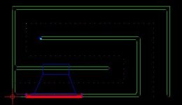
While calculating the WG profile, I was curious (hoping) if the throat surface area appropriate for a single LF driver could be simply assumed to double when adding a second identical driver? Does this also potentially shorten the total WG length?

In my case, 2 x B&C 12MH32s per side were planned for use in a FLH design similar to Inlow spec FL midbass horn. I was initially going to use a single 12PE32 per side, but started thinking about trying the altec A7 expo-reflex design instead. This brings me to the next potential issue, given the lack of rear chamber on the A7 screwing up the WGs performance. In the past, I've only built FLHs with reactance annuling rear chambers, not with the reflex rear enclosure setup of the A7. I'd imagine the transient response of a well designed traditional FLH would go south with the expo-reflex design, as most RLHs with 1/4 wave TLs would have similar issues not having any reactance annuling.

The 12MH32 requires a smaller throat entry surface area than the 12PE32, so my theory of doubling the total throat entry surface of a dual LF driver horn would allow for a shorter horn length, assuming this would be like starting the WG profile at a larger throat surface area entry point and ending at the same 1/2 - 1/4 pi mouth area? Is my theory correct on this, or am I just being misled by my morning dose of meds?

For Sale 3 SENCORE 39G292 Low Capacitance 10X Oscilloscope Probes

SOLD - THANK YOU.

Three excellent condition Sencore 39G292 150mHz low capacitance probes (photo shows 2). Note: some sources cite this as 100mHz, others state 150mHz. These are the mates to the SC3100 Sencore 'scopes, so they have both a ground clip lead and the DMM lead for that 'scope model. Two of these have the DMM lead, the third does not, so it is discounted (buy all three for the best price).

I've tested these with my Tektronix 2236A, 2465B, and Rigol DS2072A and they work great. They are a bit bulkier than Tek probes, but if you have an SC3100 and want the correct probes, or want a good set of 150(100)mHz probes for a good price, check these out.

THESE ARE NOW SOLD - THANK YOU.

Sorry, no shipping outside CONUS.

Thank you.

1:10 rule impedance matching

Hi,
In order to match impedances of tube source, attenuator and tube power amplifier to 1:10 rule I just need explenation how source "sees" input impedance. Which of this two calculations are correct:
1. Z_pot = 10 x Z_out and Z_in=10 x Z_pot (difficult to achieve)
or
2. Z_pot || Z_in = 10 x Z_out (possible to achieve)

In attached diagram C1 and C2 represents capacity of interconnect cables. C1 is very short cable, C2 is around 30cm. I don't know if they can be ignored in this calculation.
Z_out = 4K5
Z_in= from 86K (20khz) to 330K (<5khz)

Attachments

  • PXL_20240920_074151865.jpg
    PXL_20240920_074151865.jpg
    202.8 KB · Views: 163

BASEFACE 1.4D Chinese Clone distortion issue

Hi,

I’m working on a clone BASSFACE class D amplifier that was brought in with a burnt-out power supply and a dead output section.

It’s using 10 IRF260Ns for its output.

After fixing the power supply, I noticed the drive waveform on the output had a step on the turn-on, and the low-side FETs were running hot without a load at idle.

I changed the driver transistors from 2316, 916 to 2073, 940 respectively, and doing so solved the problem with the drive waveform. However, the amplifier was getting distortion well before the clipping point. The driver transistors on the low side, especially the 2073, were also running hot when I did this. I switched back to the original drivers to see if the distortion was also present with them fitted, and indeed it was, and it was much worse.

I also tried leaving the 2073, 940 on the high side and the original transistors on the low side, which was somewhat better. I also tried other transistors like 649, 669, and the results were much worse.

Any idea on what is causing this and how I can fix it?

Any help would be greatly appreciated. (I’m kind of new to fixing class D amps 😅)

Also, the rail voltage is 180 peak-to-peak.
IMG_20240923_224207-01.jpeg

IMG_20240923_224420-01.jpeg

For Sale complete F6 working perfectly but for sale sold as is for parts

I am moving out of the country in 90 days so it is time to sell the last of the stuff I have been using. My Nelson Pass F6 (see pictures) has been above my soldering bench driving some very old Bang & Olufsen Red Line 60's. It's been good! All things must pass. First the cream, this F6 was not my first rodeo and I really like the construction for the chassis. I never intended to sell it so it may encounter some "settling" in shipment. THUS I offer it up as a complete set of (working) parts.

I have been though shipping hazards before, sometimes everything goes just fine, most times things go just fine. I have no time to make things right IF they go wrong, like one channel out upon arrival. Everything is great but you must consider it as PARTS.

Everything should hold together. It is serious construction! You can see I was free with the fasteners. I am also very good at packing! I am still no match for a 4 foot fall from the conveyer.

AS an offering of parts I figure it should sell quickly at $200.00 even if it takes $100 to ship it. I live way up the Michigan peninsula in Traverse City (49685) if you want to come and get it. That would be sweet.

I also have a sweet little BA front end as preamp I'll put in a second ad to keep things straight 🙂... and Wayne's 2018 preamp, Those same B&O speakers, and cables and...

Cheers!

Attachments

  • f6 open top.jpg
    f6 open top.jpg
    510.4 KB · Views: 423
  • f6 high left.jpg
    f6 high left.jpg
    346.6 KB · Views: 419
  • evening's work done.jpg
    evening's work done.jpg
    424 KB · Views: 409
  • f6 rr.jpg
    f6 rr.jpg
    309.2 KB · Views: 411
  • f6 frt.jpg
    f6 frt.jpg
    230.7 KB · Views: 409
  • Frt rr f6.jpg
    Frt rr f6.jpg
    293.3 KB · Views: 416

building boxes for speakers

I'm working on a sound installation that will use eight of those speakers that will be placed on a floor in a art gallery.

The speakers should be as low as possible. How can I planning the wooden box? is there any rules for that?

I'm using this 4mm plywood for laser cutter for building the boxes.
I care about the esthetic of the speakers (meaning speakers must be low as possible to the floor) but the sound quality is also consideration.

Any tips?

Hi from Bretagne

Hi, I'm not an electronics engineer, but I have a friend who is. As an amateur musician, I'm sometimes confronted with equipment breakdowns, and if I can repair them myself (for faults that are easy to detect) I do, otherwise I ask someone more competent. This is what led me to your forum to help my electronics engineer friend (who doesn't have much time) find the fault with an old Philips amp that I hope we'll soon wake up. 🙂

Behringer UCA202: Fixing the Low Frequency Cross-talk

I meant to post this information 10 years ago…better late than never, I guess.

The UCA202 is not state of the art by any means, but small, light, rugged, no fiddly knobs to adjust or get noisy, and cheap…works great for non-critical travel measurement system. However, as many have noticed, if you try to use it for impedance measurements using the built in headphone amp and a 47 – 100 ohm reference resistance you will notice an issue with rising impedance error at low frequencies. I traced the problem to an unregulated voltage reference that is shared by all op amps. The op amps are powered directly from the USB +5V rather than a split +/- Supply. The voltage reference is needed to position the audio signal between ground and +5V.

Attachment #1: A trend plot of measured impedance for a 5 ohm resistor for a range of reference resistor values used with a power amp to illustrate the issue.

Attachment #2: Here is an overlay plot showing the cross-talk vs the loop-back measurement.
- red curve is the loop back measurement
- orange curve is stock unit with inputs shorted
- grey and blued curves are with inputs shorted but bigger filter cap for reference voltage
- purple curve is when input op amp reference is switched to using the regulated Vref in the PCM2902

Attachment #3: One option for improvement is to increase the size of the capacitor (C13) used to filter/stabilize the reference voltage . The board has room for a 1000uF. This is a simple option that provides about 20dB improvement.

Attachment #4: A better option, if your soldering skills are up for it, is to use a separate reference voltage source for the input op amp. Rather than adding circuitry, I found from the TI datasheet that pin 14 on the PCM2902 provides a regulated reference voltage for the internal DAC/ADC buffers. Furthermore, the TI demo board schematic shows this voltage being used as reference voltage for external op amp buffers as well.
- remove R14 & R21 (required because of direct coupling in the monitor signal path, the monitor switch will no longer work)
- cut trace between pin 5 of IC5 and the thru hole (this is the shared voltage reference trace)
- add connection from pin 5 of IC5 to pin 14 of PCM2902 (conveniently available at C1)

Attachment #5: A comparison of improvements from the two different fix options with 47 ohm reference resistor.

Attachments #6,7: Excerpts from TI documentation

* * * UPDATE * * * 2024-09-23
diyAudio member kinap35 posted links to videos showing alternative fix using an LM385-2.5 voltage reference.
This method retains the functionality of the monitor switch, if that is important.
Videos links: Post #23
Cross-talk Results: Post #26

Attachments

  • UCA202_Z_Rsense_Trend.png
    UCA202_Z_Rsense_Trend.png
    46.5 KB · Views: 1,095
  • UCA202_Crosstalk_trends.png
    UCA202_Crosstalk_trends.png
    43.2 KB · Views: 1,211
  • UCA202_Fix_01.jpg
    UCA202_Fix_01.jpg
    108.1 KB · Views: 1,370
  • UCA202_Fix_02.jpg
    UCA202_Fix_02.jpg
    114.7 KB · Views: 1,576
  • UCA202_Fix_trends.png
    UCA202_Fix_trends.png
    18.3 KB · Views: 1,164
  • TI_PCM2902_Internal_Vref.png
    TI_PCM2902_Internal_Vref.png
    28.1 KB · Views: 1,156
  • TI_PCM2902_DemoBoard.png
    TI_PCM2902_DemoBoard.png
    108.4 KB · Views: 1,530

Help 3D scan a horn

Hi all,

I guess I better post a new thread…

I have a single JBL 4367 plastic horn that is 22-1/16” wide and about 10” deep. Since I have no idea how to replicate it I imagine I can 3D scan it and use the file to print a copy or a pair.

Can anyone help with advice? Can it be done with an iPhone or I need a special high resolution scanner? Thanks in advance!

Hello from France

I'm new here and looking for informations and schematics to get a Nec A-11 amplier repaired.
I bought it new in the early 80's.
It needs some service repair for a long time now but local technician is unable to find sevice manual.
A few years ago I was in Tokyo and asked for that manual directly at the NEC company building and they told me everything was destroyed !...

Going for a PAP Trio15 DIY Project

I am a skilled wood worker and I know how to solder. I have built and helped friends build diy speaker kits before with great success. Those kits came with box dimensions and crossover schematics and part lists.

I have been scouring the internet for a while now looking for an open baffle diy kit that is similar to the PAP Trio15.

I haven't really found any kits per se, but I have found many people who have successfully built their own pair. I would like to use passive crossovers for mine. Unfortunately many of the posts I have found, people are using active crossovers such as the miniDSP. I do not want to do this. One, cost. Two, I already have a dedicated amp (emotiva xpa-2). And, three it seems most reviews say they end up sounding better with a passive crossover.

It appears many people are using these speakers for their diy builds:

1x Tang Band W8-1808
https://www.parts-express.com/Tang-Band-W8-1808-8-Neodymium-Full-Range-Driver-264-894

2x Eminence Alpha-15A
https://www.parts-express.com/Eminence-Alpha-15A-15-Driver-290-407

A lot of people also talk about using the Tang Band W8-1808 from Parts Express and getting the OB-A15Neo from PAP. However, it appears PAP is no longer selling the OB-A15Neo on its own. 🙁

Are people using the Eminence Alpha-15A as a drop in replacement to the OB-A15Neo? Could it be used as a replacement without crossover modifications?

If not, is there a replacement to the OB-A15Neo that can be sourced from someone else, since PAP is no longer selling individual drivers?

A user here, @PDRCanada, had a crossover schematic in his photobucket.

https://hosting.photobucket.com/alb...s over 100MF-100uF 33MF-33uF_zpswaualkg3.jpg

But, i am not 100% sure that is the actual correct crossover? And, if it is, can it be used with the Eminence woofer?

They also posted some photos of their crossovers as well:

https://www.diyaudio.com/community/...t-open-baffle-kits.300710/page-2#post-4958928

I am not skilled enought to be able to compare the photos to the schematic and know if I am looking at the same thing.

I have posted a follow up, asking these questions, but then I realized that this community seems to like when new threads are created, so that is when I created this.

Any help in getting me started on the right direction is greatly appreciated!

Thanks!

Heater Wiring - the Good the Bad and the Ugly

looking over photos of DIY projects on the net, and hearing the many stories about hum, makes me want to offer some observations that might help amateur builders.


Understanding the problem of tube heaters and hum is the first step toward ensuring your wiring job will be good enough to give happy results (no hum).

(1) The heater supply is usually A.C. (alternating current), a 50 or 60 cycle voltage taken from a winding off of the power-supply transformer. As such, it is usually more or less a sine-curve (but often with additional components, harmonics), but can actually appear as gross as a sawtooth depending upon the quality of your line voltage.

(2) For hi-fi and musical applications, the heater lines unfortunately provide a way in for noise from the mains (random hash, transients), and also radio frequency noise (RF), because the wires can also act as antennae, picking up noise from nearby motors and other equipment.

(3) So even if you don't convert your Alternating Current (A.C.) power to Direct Current (D.C.), you will still want to have some filtering and protection from line and radio noise.

(4) Also, if you don't convert to D.C., the 60 cycle A.C. hum will leak into other nearby circuits through the electromagnetic field coming off the heater wires, unless you take some precautions.

(5) As well, noise from other parts of the amp (the High Voltage HV supply, the screen supply and bias supplies) can also pick up and inject noise back into the heater lines.

(6) Many people don't bother to convert A.C. to D.C. for the heaters, and so other methods must be applied to minimize hum and noise. This is sometimes a cheaper solution.

In any case, hum and noise remains a problem with amplifier circuits, so basic strategies should be used.

Regardless of whether or not you convert A.C. to D.C. (removing most of the hum), the Mains coming into the amp should be filtered and/or isolated from line noise. This can be done with a basic capacitor network on the lines.
It can be built into the line plug:


-----------------------------------------------------
Next, comes the layout of the heater wiring itself.

(1) The A.C. supply wires are twisted together, to collapse and minimize the field around each. At the same time as current flows in one direction on one line, it is returning in the opposite direction on the other line, and the two fields interact and cancel each other out.


(2) But there is ANOTHER reason
why the wires are twisted together, which is often forgotten or neglected: It also stiffens the delivery system and minimizes movement of the wires. What movement? Any motion in a wire carrying current, or in a magnetic field generates a signal, or creates a coupling field. The motion can be very small, almost invisible, as in a guitar or violin string. It will still be very significant here.


The practice of twisting wires is also done to greatly stiffen them, minimizing motion and coupling fields.

(3) This is also the reason why SOLID wire (such as 18 to 14 gauge) should be used for heater leads. In fact, any and all electrical activity has an impact on all metal in the area, and in case you haven't guessed it, will also cause physical forces of motion on the wires. Here we DON'T want flexibility, but rather stiffness.

If you doubt this, or think it is insignificant,
try loosening the bracing bolts on your power transformer,
and listening to the horrible vibrating rattles as the E-I sections bounce around.

(4) Getting back to the theory behind twisting the wires, We want to recognise also that the number of twists is also strongly related to the DISTANCE to the next object that might pick up the signal, by the Inverse Square Law:

Quote:
"The circuit is essentially a coreless electromagnet with only a single turn of wire. By twisting the wires, we produce many small electromagnets, instead of one large one. Furthermore, these many small magnets are pointing in alternating directions. If we were very close to one of these magnets, we could still detect it, but once we are a small distance away, the adjacent opposing magnets will cancel it out (figure 3)."


Thus we want as many twists as possible (per inch), to minimize the proximity effect to other nearby objects.

On the other hand, if you twist the wires too tight, you can also short them or break them or weaken them to the point where they generate resistance and heat unevenly, so there is a limit to how much you can coil / twist the wires before you risk damaging them.

Now we are ready to understand why many seemingly good efforts at heater-wire dressing fail.

The hum is directly related to distance:

(1) The most sensitive components are the ones closest to the heater wire. That would be the area right around the socket! This is typically where the twisting-dressing technique is done the most poorly and sloppily!

(2) Wires at a right-angle to the heater-wire are the least sensitive to hum. Often wires and components are laid out badly in regard to this obvious issue: orientation.

(3) Other components may or may not be more or less sensitive to heater hum depending on orientation.
THERE ARE NO general rules for this. For instance, its a bit tricky to orient a coil (or a cap!) for minimum hum, because it has a 3-dimensional field! Some components will be sensitive in ANY orientation, and must be shielded.

Rockford Fosgate Punch 600x4

This Rockford Fosgate Punch 600x4 I have here came in with one defect channel.
Exchanged:
2x IRF 5210 and 2x IRF3415
R229 10 ohm
R228 20 ohm
2x 0,1 Ohm (drain/source resistors)
2x 0,05 Ohm current sense (R245/R234)

When starting up, the power supply is pulsing on/off/on like 5Hz., like it's in protection. No LED is on.
Checked the board, but cannot find any burnt or defective part, all output mosfets are ok.
I think there must be something wrong in the defective channel.

Without the rectifiers MUR1620's the power supply works normal, LM337/317 low power supply is ok.

Is there a schematic available or any ideas?
Board number 1325-57685-03 or 1405-57685-03

Thanks in advance.

Level shifter using pentode and schade feedback?

Hello all. I am working on an OTA, OTL, OCL, OCD : P headphone amp for a friend. He loves his HD800s and the impedance never drops below 300 ohms, so I have the following circuit idea.

1726534140012.png


We have a couple problems with this circuit. 1: I would need to interface the incoming ac signal with a circuit that is sitting at ~ -155v 2: The input capacitance of the 4P1Ls would be pretty high and require a fairly beefy driver.

Both requirements can be solved separately, however, is there a way were we can kill two birds with 1 stone? Short answer? Maybe. I'm not really sure and I could use some help.

Here is my test circuit. The idea is to create a cathode follower where the output sits at ~ -155v. The signal is fed to G2 instead of G1. This allows G2 to remain at ground potential whilst G1 and the cathode can be shifted down towards the negative supply rail. Finally, I am trying to incorporate schade feedback in order to have triode like performance at the output.

1726536141305.png


In this circuit the cathode does sit at the correct potential! Yay. Level shifting achieved!

Only 1 small problem. I hardly get any output signal. Where I would expect to get nearly 1v out (0.95v ish), I only get 6mv out 😢

I am hoping some of you might be able to enlighten me on what I might be missing here.

Designing a "tapered" port?

I've seen subwoofer designs where the port has a very restricted center section, and gradually tapers towards both ends. Sometimes they have an almost elliptical flare at the exit. I don't know what they are called, so if you know what they are called, that'd be a big help!

For the record, I don't mean a straight port with flared ends.

Examples are Genelec and their LSE subs, and I have seen pro audio speakers that use ports like this also.

On the Genelec, I suspect the restriction in the middle of the port reduces turbulence, since the port follows an arc. And on the pro audio side, I think maybe it allows a shorter port length while minimizing port noise/ resonance?


I'm asking because I built a radius port awhile back, and now I am interested in trying to improve the design. But I was just guessing, and I don't know the theory behind such a port.

The port I designed has a 10% restriction in the center. To determine port length, I made the inner and outer surfaces the length that VituixCAD calculated. (I used the length of the surfaces based on the realization that air flow will "stick" to those surfaces.)

20230615_202227_resized.jpg


My assumption about a radius design is that there will be turbulence as air reverses direction rapidly while trying to follow an arc. So my intuition says that restricting the port cross section in the middle section compresses the air, reducing this turbulence.

Questions I'd like to answer:

-Are my thoughts even remotely close to being accurate?

-How much restriction can I add before hurting the port's output?

-Do I need a specialized tool to calculate this type of port, or can I start with a calculation for a straight port?

-To achieve a desired tuning frequency, do I have to keep the port's internal volume the same as what a calculator says?

-Or does the restriction in the middle of the port offset the reduction in internal volume?

I will probably do some experiments at some point, but I don't know when that will happen. I'm in the middle of a long term project that deserves my full attention, so if you see me doing subwoofer testing, you will know that I am being irresponsible... 😛

Hello from Dayton Audio

First off we would like to thank you for allowing us to be a member of this great community. Any questions you may have regarding our products we would be happy to answer, as well as any helpful tips or tricks you may need along the way.

About us:

Innovation. Value. Quality. Aren’t these what you want in an audio product? There’s no reason to settle for anything less. Dayton Audio’s mission is to calibrate a fine balance between technology and art in order to exceed our customers’ expectations. Competitive costs and after-sale support also feature heavily in Dayton Audio’s vision of excellence. Our engineering team collaborates with OEM/ODM partners in order to create optimized, personalized product platforms. Dayton Audio’s experienced team of designers places a high value on technical excellence, product reliability, and consistency of electro-acoustical performance. Our 20+ years of inspired, rational engineering has led to international acclaim by the loudspeaker community in particular. Never, in the pursuit of our audio goals, do we compromise on functionality or quality control.
For over two decades, Dayton Audio has specialized in audio components, particularly the field of loudspeaker design and production. While most of the engineering and development work is performed in the US, Dayton Audio goods are manufactured in North America, Europe, and Asia. This synchrony offers benefits of quality, logistics, and performance without compromise. Throughout the years, Dayton Audio products have received acclaim worldwide and are often compared favorably to similar items costing far more.


When people talk about reasonably priced, high-quality audio speakers and electronics, they talk about Dayton Audio.
They say things like "the best sounding" and "speakers of this quality tend to cost 3-4 times as much."
Dayton Audio delivers the engaging sound, unbeatable quality, and dedicated service you'd expect from a high-priced brand... but without the premium price.
  • Like
Reactions: stv

Yamaha DSP-AZ1 issue

Hello everyone,
I have a YAMAHA DSP AZ1 that has the following problem. Any digital input used COAX or optical emits sounds only from the right channel (A and B), also the headphone output emits sounds from only one channel, I assume the right.
If instead I use any analog input, these work perfectly and for all 8 channels + the sub.
The Channel Test mode emits sounds only on the right channel.
I have already read the entire service manual and the user manual, I could not even find how to restore the amplifier to factory conditions.
Do you have any ideas? Could it be a disconnected connector? What should I check?

Thanks

Programming and Coding for Putzeys Balanced Preamplifier with MUSES72323 Volume

Both sets of code have been used in anger:
Arduino Nano code
The Nano code runs on my old controller board which houses a piggy backed Arduino Nano, a PEC11R/ Alps EC11 rotary encoder, TSOP4836 IR receiver and a ULN2003A darlington array (used to drive separately mounted source select relays). It also feeds i2c data to a 20x40 LCD display.

ESP32 code
The ESP32 code runs on my new controller board housing an ESP32-DevKitC V4 dev board, PEC11R, TSOP4836, and ULN2003A. Apart from the ESP32 in place of the Nano, it also feeds SPI data to an on-board 2.8inch TFT display. Two issues I came across while getting the ESP code working on my new controller board were
  1. The TFTeSPI library runs the ILI9341 TFT SPI write clock rate as 40MHz. This is 4 times faster than the data sheet and on this set of hardware /ribbon cables is way too fast. The data sheet figure works absolutely fine in this instance.
  2. The initial hardware/software worked fine on the bench power supply but didn't want to power-on with the pre-amp's power supply . It was happy to work if the reset button on the ESP dev board was then pressed. This was due to the pre-amp power supply had a softer start-up time. (slower than the ESP's dev board's existing reset timing. A 10uF from the ESP32 reset pin to ground cured the problem.
In the coding, my remote control uses RC5 protocol as this is the coding used by my existing commercial sources that feed the pre-amp. It's straightforward to substitute other coding. Just google for whatever you need (Apple, NEC, whatever).
Hi geoffw1!
I need help uploading the program. I have purchased an ESP32-WROOM-32D, what program can I use to upload the ESP32 code that you have generously provided? Platformio+VSC gives errors.
Thanks! D'

Subwoofer Decisions - UM18-22

Hi all,

I've been working on many aspects of a new home theater setup and in the process have built a Full marty sub with an UM18-22.
I thought I'd go big as I could fit it in one corner of the room.

Upon testing, I don't think the corner is ideal, lots of nulls in the room, it's certainly powerful at certain frequencies at certain locations but I'd like to put some
more effort in and I think i'll go dual subs to help even things out.

If I go dual subs, I can't fit another full marty, so its either duall marty cubes, or i'm considering a sealed option.
I have the whole front wall I could use to position those subs, they will fit height wise to go anywhere along there.
I'm not completely sold on ported, as I probably use the system for maybe 70/30 music/movies.
If it's more for music, should I look more towards 2 x sealed subs for the SQ?

Current setup is NX6000D amp, minidsp 2x4hd.

Thanks heaps!

Revisiting XOC1 TH18 EPA Mod 30Hz with SBA 18SW1900D

Guys,
does anyone have the plan for the moded XOC1 TH18 made by EPA
i was looking on my SUB plans folders and cant find it

while browsing trough my HR saved screens i found the EPA screen and when on it
i simmed some drivers and the

SB Audience Nero-18SW1900D 18"​

caught my eye on how it sims ,looks good
it can take 1kw to hit xmax at 30hz
the sompresion ratio is almost 3:1

does a BL of 28 for that driver will cut
not risking the driver cone get shredded to pieces ?
SBA 18SW1900D

1720452523530.png
1720452543348.png


1720452148819.png
1720452176191.png


1720452325693.png
1720452382453.png

Beginner PC DSP digital crossover Q

Hi,

So say you have a 24/96 audio file. 24-bit provides 144dB of dynamic range between the noise floor and 0dBFS.

Say I then use a software DSP to break that into LF/MF/HF. Let's say, as an example, 20-400Hz for LF, 400-3000Hz for MF and 3000-20000Hz for HF.

Each of the three DAC channels can do 24/96.

Am I barking up the wrong tree here, does that give us stupid (wasted) amounts of dynamic range per channel?

16-bit provides 96dB of dynamic range between the noise floor and 0dBFS, so should the DAC channels just use 16-bit then?

Then there is DSP volume and volume levelling, my basic understanding of these comes from Roon and I seem to remember it converts the audio bitrate to a 64-bit float internally (I think CDSP is similar) and therefore DSP volume is lossless (because the dynamic range is huge) as far as human hearing is concerned?

I don't really understand how DSP volume and volume levelling impacts the DAC output bit depth? On my DAC8X a post by Renne over at ASR was complaining in the "Multichannel audio on a Pi will get a whole lot easier and cheaper!" thread that the DAC8X was only 24-bit and in their words he couldn't use it's 24-bit limitation because "24-bit dynamic + 8-bit volume control = 32-bit".

Apologies of this doesn't make any sense, I'm learning.

Thanks!

For Sale Toshiba 2SK170-BL

I'm no longer selling the unmatched ones, now I only offer the matched ones (quad/octet).

I matched them within 0.05mA, guaranteed no more than 0.1mA (10V/25°C).

Price as follows :

$13 (quad) & $24 (octet) for Idss 6 mA range (only few sets left)

$16 (quad) & $30 (octet) for Idss 7-8 mA range

$20 (quad) & $38 (octet) for Idss 9-10 mA range (only few sets left)

Shipping by Registered Mail would be flat @$10 (Worldwide).

The last photo was taken from an old Sansui board, just to prove that the JFET with the marking like the one I'm selling used to exist.

Guarantee these are genuine Toshiba, If not, just send them back to me (I'll cover the returning cost) and get your money back.

PM me if interested

Thanks

Attachments

  • Screenshot_20220910-184030~2.png
    Screenshot_20220910-184030~2.png
    596 KB · Views: 397
  • 20220826_102127_HDR.jpg
    20220826_102127_HDR.jpg
    461.6 KB · Views: 417
  • IMG-20220914-WA0000~2.jpg
    IMG-20220914-WA0000~2.jpg
    84 KB · Views: 406
  • Screenshot_2021-01-06-09-14-08~2.png
    Screenshot_2021-01-06-09-14-08~2.png
    1 MB · Views: 258
  • Like
Reactions: birdbox

Driver characteristics for small enclosures?

I've acquired a woofer from one of those, back in the day, Japanese systems incorporating the superwoofer. It's a 10" driver with a serious mechanical X-max. I've no clue as to the TS parameters. It struck me - these drivers were crammed into very small cabinets.
I modelled a random Eminence 10" driver in a 20l cabinet. The results were awful, f3@80hz, +5db @ 200hz.
What characteristics does a driver require to work in a small cabinet.

Aiyima A07 Mods

Hi Have you heard of or done any mods on the Aiyima A07.

I've got BB 827 op amps on adaptors that i am thinking of using, also a meanwell 10 amp psu to upgrade from the stock 5 amp is coming in next week, hopefully on monday.

Is there anything else that can be done such as input cap, or any other caps; output inductors, what would you upgrade to?

Many thanks

AM I CRAZY? DIY nearfield nude driver desktop headphone concept

I think I have a crazy idea... or maybe not so crazy (but for DIY only!). Read on for details...

I've often espoused the use of a nearfield driver for the "ultimate fidelity" subwoofer. Assuming this would be used when you are seated in one place only (e.g. at the computer) for music listening, the idea is this:
  • Construct a means to place a large-ish (e.g. 12 or larger) diameter driver right behind your head or as close as possible to this location.
  • The driver is mounted in a minimal open baffle or very shallow open-rear baffle-and-2-sides frame.
  • Because of the driver diameter and the proximity of one's head to the driver, you are in the nearfield. As such, the response will be essentially the infinite-baffle response of the driver.
The idea is that the "ultimate" bass extends low in frequency, is free of cabinet resonances and small-box-distortion, and has no peaks and valleys from room modes. About the only way I know of achieving this apart from being in a very small space like a car cabin is via the nearfield method. I happen to have the perfect driver for this - a 15" free air type subwoofer with Qts=0.7, Fs=20Hz, and 15mm Xmax. If I listen to this in the nearfield the response should be essentially the infinite-volume, closed box response! Wow. So that would cover the bass nicely.

I started wondering to myself lately if this concept could be extended to the full audio spectrum, that is to add a driver on either side of my head near my ears. If the drivers are large enough in diameter, I would again be in the nearfield (up to some relatively high frequency at least) and I would be creating something like an open-back headphone but with completely open-air drivers. Is this a crazy idea? Not sure, I have never attempted something like this. I am concerned that above 1kHz or so, some odd effects from the interaction of my head and the driver (e.g. interference) will take place and the frequency response will be anything but smooth. Also, there will be no way to measure the response (I like to measure) so I will need to adjust any FR irregularities by the "seat of my pants" (e.g. by guessing).

Can anyone recall something like this - a full range nearfield "listening station"? Could this bring some real high fidelity in a DIY-only package? I might have to build a "listening throne" (e.g. a chair-and-speaker contraption) test bed.

Any thoughts on driver selection (size, type, etc) for full-range nearfield listening are welcome. What is the best way to implement this idea?

Good Alternative to Guilford of Maine

I am trying to build some acoustic panels for cheepish and have found that the most expensive part is the fabric. I am building 12 2x4 foot acoustic panels (4 to 6 inches thick) with Knauf insulation. And at that scale the GoM fabric is over 500 to cover it. I am looking for recommendations for a cheeper fabric that will look almost as good and keep the insulation in. The Isolation and fabric is linked below. Also if you recommend a different insolation that will do a better job of broad band absorption i am open to that to.

Insolation:
https://www.gikacoustics.com/product/knauf-rigid-fiberglass-1-6-lb/
Fabric:
https://www.gikacoustics.com/product/guilford-of-maine-fabric-by-the-yard/

Counterpoint SA-1000 volume pot replacement

This is my first post here, and I am hoping to obtain some help replacing the volume pot on my Counterpoint SA-1000. I hope that I have posted this in the correct area this time🙁. I have tried a couple of other avenues for answers, but have received no help. On to the experts... About four years ago I did a recap along with some parts upgrades (nothing substantial IMO), but would like to replace the stock volume pot. I have already ordered a replacement AudioNote, and I am aware that it has six tabs instead of eight as in the original. I have seen a few images of a different (six tab) pot installed, and can see that the extra two wires can be doubled up with on two of the tabs on the new pot. I have a schematic, but I am not knowledgeable enough to figure out how to do this. If anyone can help with this, I would very much appreciate that! Thanks, and thanks for all of the unacknowledged help in the past. Kevin

Attachments

Multi-Driver-Opposed Open Baffle Subwoofer Questions

Hi all,

I have built several sub designs and enjoyed them and recently did an open baffle subwoofer with 4 drivers in it and I liked it a lot and I also did a dual opposed sealed sub recently and I really love how dead the box is. It got me thinking more about how to mass up some open baffle subs but to take advantage of some other concepts mixed in such as doing open baffles that are opposed to cancel the structure vibrations.

I have 8x 12" drivers just sitting, waiting for a project, so I was thinking of a segue into an experiment (for me at least) to explore this with them. I don't see much of this when I search but I'm sure it's been done many times and maybe it's just not great for the effort and cost, I don't know. I do know that I liked my 4 driver open baffle sub a lot. And I like my dual opposed sealed. So I'm thinking I'll throw together a basic platform to test these 8 drivers to see how it behaves and sounds (full active DSP to shape the output).

I'm thinking of two baffles, front and back, 4 drivers per baffle, opposed arrangement and all in phase so that structure vibrations are canceled. My goal is to build these taller like towers, 4 drivers tall basically. The opposed arrangement would be to keep the scaffold tower dead and from shaking so so that the drivers don't walk around flapping in the air.

What I'm curious about though is how the drivers will interact with the room. Off axis will still be lower right? So floor proximity shouldn't get pummeled the way a sealed sub does? I ask because of the idea of exciting or coupling heavily to a wooden subfloor vs concrete. If the drivers are 90 degrees off axis from the floor since they will face into the room, will the floor receive as much energy under the scaffold tower as a traditional cabinet sub?

Very best,

Old interstage transformer pinout (B, P, G, F?)

I have some old interstage transformer I want to use, and I used to know it, but now I am not so sure, as it's been some time I don't deal with these pinout labels.

They are usually marked as B, P, G and F pins for a SE plate to Single grid.

As far as I remember, B+ voltage goes to pin "B", and the tube plate goes to pin "P", am I right? I am not sure anymore.

And also, I don't have a clue about "G" and "F".

Is "G" for the grid, or ground?

And what the hell does "F" stands for?

I hope some old tube head sees this thread and help me, because I've searched with Google high and low, and I can't find an answer to that.

Thanks!

Dual 701 turntable assembly problems

Hi All
Servicing a Dual 701 turntable and detached the Cam wheel the wrong way.
Now I got these two small parts (#146 Pawl and #145 Tension spring)
1000004784.jpg


And have no idea how to fit these. Service manual doesn't give any help, so do we have a Dual expert here?
I think it must be close to this, but where to attach the spring?
1000004785.jpg

Any help appriciated

Attachments

  • 1000004784.jpg
    1000004784.jpg
    348.8 KB · Views: 113

Introducing myself

Hello,

Introducing myself here….

Audio enthousiast for some years now.

Sometime came across a pair of Reference 3A MMC speakers and have been hooked since then by the brand.

Playing with a Line Magnetic LM-518ia amplfier, a DIY built DDDAC1794 streamer DAC and a very nice Thorens TD125 lomgbase with Ortofon SPU.

Have been repairing lots of speakers for others also. Always looking for (small) improvements 🙂

Happy to join here!
  • Like
Reactions: Freedom666

Can I use these drivers this way?

I have a pair of Dayton DC50FA-8, which are 2” dome midrange drivers. I look through their data sheet and wonder whether I can use them without low-pass filters. I mean to treat them as the tweeters, no low-pass for limiting high frequency production but only high-pass for preventing damage from low frequency, is it possible? Because I see no break up occurs at high frequency on their frequency response curves. I also have a pair of 19mm. Scanspeak HF drivers and plan to use them as the super tweeters. If it’s possible, which frequency is recommended for crossing over the super tweeters to the 2” Dayton tweeters?

Attachments

MAOP 11 in Erich's slot vented box

Hello all,
After being a happy listener for several years with below speakers, I am planning upgrade drivers to MAOP 11 in place of Alpair 10.2
https://www.diyaudio.com/community/threads/erich-hartmann-alpair-10-2-bookshelf-speakers.227999/
so I have few questions,
1. is there going to be considerable sound quality upgrade from A10.2 to MAOP11, given the huge price difference between them?
2. I am using class AB 80W amp for A10.2, whats recommended for MAOP11?
3. can the above Erich's slot vented box can be used with same dimensions for MAOP11? or there exist better design? I see below designs in the MA site,
Lhotse-MLTL-11.2MAOP
MAOP11.2-TL
MAOP11.2-RTL
LS-MAOP11.2
4. are they good to handle bass frequencies as good as or better than A10.2? or should i consider adding sub/woofer?
5. do they need tweeter? I see one guy used tweeters
https://www.diyaudio.com/community/attachments/img_20211123_123101-jpg.999675/
6. How do they perform near field listening. Just 8 feet from them?

thanks in advance

Dayton Reference RS270-8 10" Woofers (almost new in original boxes)

For sale: One pair, Dayton RS270-8 10" woofers. Woofers have been briefly mounted to test, but have less than 10 hours of use.

dasyton_reference_10s.jpg


One of them has a cone blemish- the other is in cosmetic perfect condition. Spiders are perfectly flat (no cone sag).

dayton_reference_10_blemish.jpg


Selling for $130.00 for the pair, plus shipping.

Would accept up to two Dayton Audio DCS165-4 6.5" subwoofer drivers and/or up to four Dayton Epique E180HE 7" passive radiators in partial or total trade toward these.

Located in Kennesaw GA. Local pickup definitely available!

If replying to this- please also send an email to gwaters@inbox.com, as I don't get to check in here as much as I used to...

Thanks!

Regards,
Gordon.

Intro and DIY

Hello folks,

I've been an audiophile and electronics tinkerer for over 40 years. Current I've begun my journey as a Pass Labs owner with the purchase of a X150.8 power amp. It's partnered with a BAT VK-80 preamp and drives a set of Zu Definition 3 speakers.

My drive to join the forum is also due to my NAD 3020A restoration project, and would always love input and help.

Neil

For Sale High-end DIY speaker project (Eclipse 1238R, Madisound 8252R, Focal 7V313, SEAS 27TFFC, enclosures

For sale: Very high-end DIY speaker system, I helped design and build about 20 years ago. It is a project- as it will require some re-building.

madisound_custom_triamp_front.jpg


This system is four-way, tri-amped, with passive crossovers (included) between the midrange and tweeter. Drivers per channel are: tweeter: 1- SEAS 27TFFC, midrange: 1- Focal 7V313, mid-woofers: 4- Madisound 8252R 8", subwoofers: 2- Eclipse W1238R.

madisound_custom_eclipse_w1238r_subwoofers.jpg


The cabinets for the mid/tweeter and midbasses are Woodstyle, from Madisound. The mid-high cabinets are sealed, and the midbass cabinets have one Dynaudio aperiodic Variovent in the rear of each cabinet. The mid-tweeter cabinets are in good shape, including grills, but the midbass cabinets will require some repair, as there is some damage to the plinths of the cabinets. The cabinets themselves are in good shape, save for one missing grill- but the plinths have gotten slightly wet in storage, and will need some remediation. The cabinets for the subwoofers were built-into the wall of the original installation- and were not save-able, when this system was removed. I do have the specs for the subwoofer cabinets.

This system, as mentioned, was tri-amped. We originally used a Madisound Sledgehammer 3-way active crossover and a couple of four-band parametric EQs on the bass and midbass- but, all of this function could be much more easily accomplished now, by something like a DBX Driverack. That's what I would recommend, wholeheartedly. I can give the buyer a good starting point for the crossover settings in the Driverack (active crossover points of roughly 50Hz and 400Hz). The original passive crossovers (2.6KHz) between midrange and tweeters are also provided.

I don't know of any practical way to ship this- it's available in the northern Atlanta GA USA area (I'm in Kennesaw GA, but can drive to meet within reason- I have a pickup truck with covered camper shell).

Asking $600 for the lot.

This, frankly, was one of the finest audio systems I have personally encountered anywhere- and that includes very high-end systems I have worked with, that have price tags of into the seven-digit-dollar amounts. I would really enjoy having someone put it back into use...

Thanks!

Regards,
Gordon.

For Sale Amber 3501a Audio Distortion and Noise Measuring System

This is a really nice condition Amber 3501a that I bought a few years back to fill a gap while soing some maintenance on my other analyzers. The previous owner adapted this unit for his convenience when working in the field and at his shop on audio amplifiers. He changed the BNC generator output jack to an RCA jack, and added banana jacks for easy hookup of amplifier outputs. To switch between channels for taking measurements, he changed the front grounded/ungrounded input switch to switch between banana jacks (Input 1 and Input 2).

Here it is testing a buffer/preamp with very low output showing good sensitivity. I've used it for testing a few Adcom amps and it worked well, but as you can see from the unit beneath the Amber, I've moved into a different type of analyzer, and still have my early HP analyzers, so this is ready to move to the next person who wants a quick and easy way of testing functionality and performance without going into a more expensive system, or a more fiddly/time consuming approach like a soundcard and REW. Actually, I have those systems as well, and each has its own place. I find these self-contained distortion analyzers to be best for initial function/performance testing of units I'm evaluating prior to and after repairs.

When I bought it I cleaned all the rotary switches and board connections, inspected the boards and terminations, tightened various fasteners, and re-painted the front corner brackets.

How about $350 plus shipping and PP fees (CONUS only, please)? I can provide two PDF manuals for the buyer - the slightly different 3501 and for this 3501a. Thank you.

gktaudio_Amber3501A-2.jpg

gktaudio_Amber3501A-6.jpggktaudio_Amber3501A-5.jpggktaudio_Amber3501A-4.jpggktaudio_Amber3501A-3.jpggktaudio_Amber3501A-1.jpg

Best LDR for Sound Technology ST 17xx gear

Since there is little mentioned on the 'net re Sound Technology gear, perhaps it would be a good idea for those who have successfully repaired their gear to list the LDRs used along with any mods they have made to the circuit(s). Both in the Oscillator & Analyzer sections.
As a folllow up, they can comment on their findings. In addition, it would be helpful to establish a listing of results using different LDRs in different locations on the analyzer board.
ANALYZER BOARD
U205
U206
U207
U208

U7 (OSCILLATOR board)

The 17xx models share similar LDR circuits.

Whammy Custom PCB + Dual Mono PSU + Muses 72320 Vol Control

Another day, another finding,

for sale is a set of custom PCBs for Wayne Colburn's Whammy, just a different approach (and a bit better sounding as I listened to about 3 versions of it). Designer of the set is a very professional DIYAudio member who puts a lot of passion into his routings and PCB making. The special thing is, you can put the Amplifier backpack on the PSU with appropriate Spacers and thus fit it into a 3U Galaxy Case from ModuShop (230x280), by using L-shaped aluminum heatspreads you can dissipate the output transistor heat directly to case without the need of a dedicated heatsink. The other thing making it special is the PSU (or UPS how the designer called it). It's a dual mono cap multiplier with HF and LF filters, thus very silent ;-). The amp board is nearly fully stuffed, only 4 resistors and a few caps missing. Stuffed with original BB OPA604. The muses vol. Control can be directly supplied by the PSU and does not need any special PSU

Consists of:
  • Whammy Board nearly fully assembled
  • A set of nicely matched 2SK2013 / 2SJ313 Output Transistors
  • Dual Mono PSU cap mulitplier PSU
  • Muses 72320 Vol. Attenuator

I paid a total of around 230€ for everything,
asking 200€ + shipping + PP fees.


IMG_6971.jpegIMG_6972.jpegIMG_6970.jpeg

A built variant on bench for testing before it went into the enclosure (I know its dark pictures, just you get an image of how its backpacked).


IMG_1453.JPGIMG_1454.JPGIMG_1455.JPG

NJW Symasym - potential GB Interest

This will probably the last chance to get Rudi_ratlos latest iteration of Symasym boards as it will also be one of my last group buys for this. It's a great sounding amp, check on Forums for more information about it.

It's the latest version with 2 pairs of NJW output transistors. houses a speaker protect circuit (that does not have to be populated, but why wouldn't you). Board size is about 215x95mm. The board shares the option to power the front end of the circuit with a dedicated PSU by setting jumpers.

Price will depend highly on several factors as:

  • Number of interested builders
  • 1,6 / 2mm PCB
  • Min. is HASL-lead free
  • PCB color ;-)

I ran it through several well known PCB manufacturers and I came to about 14-15$ for a single board, not including taxes.

Please share your thoughts and interest that way. If enough people are interested, I will quote for the most requested.

#1 DIYAudio Name / Country / Qty of PCBs / Color (Green / Black / Red / something else) / Thickness (1.6 or 2mm) / HASL-Lead free or ENIG


Bildschirmfoto 2024-09-09 um 10.09.05.png
  • Like
Reactions: platon.rado

Increased voltage supply forYamaha SC-02

I have one of these Yamaha SC-02 mini guitar practise mixer things. It runs on two 1.2v - 1.5v batteries.


I was thinking of powering with a bank of four 18650s which would sit underneath quite nicely.

I'm wondering if I need to add a regulator, the device appears quite analogue, so I was wondering if upping the voltage to 4.4v would be detrimental to it's functioning.

Posted in headphones because it's designed for headphones, and I use it as a little headphone amp, it even drives my old 2k ohm DT-100 nicely.


IMG_0545.JPG
IMG_0547.JPG
IMG_0548.JPG
IMG_0178.JPG

For Sale ES250 horns with GRS PT6816 drivers

For sale is a pair of Joseph Crowes ES250 horns loaded with GRS PT6816 drivers (2 per channel). They measure flat from 250hz upto around 10k when the drivers start to drop, usable upto 13k hz. They are set up with the back open, so you get a nice cardioid response, with a nice airy sound, very cohesive as no xovers in the critical listening band. I used them for a bit just with some bass cabinets, ann enjoyable experience. They aren’t finished, just as they came off the CNC. The limitation of these horns is they must be set up vertically at the ear height as the divider in the horn introduces lobing. In one of my audio meets there was a discussion of adding a ktube into the divider for the top end. Unfortunately they have been sat gathering dust, as I build something else🙂.

It’s hard to price these as they were a prototype, and they aren’t finished, just as they came off the CNC.. Accounting for the 1 and 1/2 sheets of birch ply I used to build them, and CNC time, I think £500 the horns and drivers seems fair.
Pick up only. I am in Nottingham, England.

Attachments

  • IMG_0213.jpeg
    IMG_0213.jpeg
    353.2 KB · Views: 72
  • IMG_0214.jpeg
    IMG_0214.jpeg
    393.8 KB · Views: 76
  • IMG_0215.jpeg
    IMG_0215.jpeg
    391.7 KB · Views: 75

SketchUp 2017

Guys,
I tried freecad..... Like for 2 months...

I was able to make the panels of a cabinet
But can't join them to the actual layout

I always got...
"Too little constraints ....or too many constraints"
Suuuuuu.....,.k

Soo ...long story short
I found SketchUp 2017 on my aux external HD
That I have forgotten

Ok ... Long story short (again....gezzz)

SketchUp clicked for me!! For cab layouts

So... Google was the maker of SketchUp as free app...but Trimble bought it...when ? Can't tell , so... They removed the free version of it ...

And .....,.......,..,..
I found a 2017 copy of it on and external HD

I tried and it works on win10

Is the last freeeee version of SketchUp
V17
If you want it , let me know

Trimble removed it from the website
So if anyone want it.... It works
Today V17

Trimble don't have perpetual licenses....
They want pay as you go!!!

I hate the
"You don't own anything...but you will be happy"
Model!!!!

rear chamber on a t-line

Is it possible have a chamber behind the driver in a T-line enclosure to accommodate the drivers magnet? I have a nice 12" sub but trying to keep the lines sq cm patch close to the sd of the sub while making enough room for the magnet is impossible with this sub. How important is it to keep the patch as close to sd as possible? The best I can do is double baffle the front and gain another 3/4". With just a single baffle the line needs to be 690 sq cm where the Sd is 471 sqcm. I got the drivers required space by taking the diameter of the driver times the mounting depth of the driver plus 1 inch. Am I overthinking this? Sorry if these seem like silly questions. I'm just learning horn building but am very much interested in learning all I can. Thanks. I know the drawing is far from perfect. I'm also trying to learn librecad but the scale is there as far as line width and driver depth. The dotted line was for me to measure length.

EDIT: Thank you for everybody that replied. Surprisingly I wasnt berated by a dozen people but instead got good feedback and learned something. Downside of the internet is once somethhing is out there, its out there. Bad info and all.

Attachments

  • driver issue.JPG
    driver issue.JPG
    14.4 KB · Views: 55

Digital Control of Attenuation – Repository for DIY

I’m starting this thread in the Pass Labs sub-forum, because I think there is a need for this information here, and because the idea for a digital attenuator came while building the excellent Iron Pre by Zen Mod.

There seems to be interest in a repository for free information pertaining to digital attenuation systems, in particular the Muses family of chips: 72320 and 72323.

Over the years, there have been a number of attenuators available using the Muses products. Some are commercial, but most were developed in-house by DIYers. Therefore, there is likely to exist quite a lot of knowledge in the community about implementing Muses chips.

If it weren't for generous people like Nelson Pass, Wayne Colburn, Zen Mod, Mark Johnson, XRK, 6L6, AKSA, Salas, and many others, our DIY efforts would have looked very different. And since this forum is called diyAudio, we should embrace the culture of sharing. So, in the spirit of DIY, I encourage everyone who can contribute, to share information about digital attenuation, no matter how small.

In this thread we can collaborate and share information for building our own Muses attenuators. Feel free to share your microcontroller code, libraries, schematics, tips, experiences, etc. as well as questions.

I’ll kick off by listing an Arduino library for the Muses72320 by Christoffer Hjalmarsson: github.com/qhris/Muses72320

* New - Updated library to include gain function and also other updated functions: MUSES72323 Library

Muses72320 datasheet
Muses72323 datasheet

Arduino libraries & code (generously supplied by @Nikon1975) - added 23 Sep 2023
Muses72320 Library
Muses72323 Library
Arduino code (full preamp code, including Muses72323) - added 26 Sep 2023
Arduino code for Muses72323 (Muses72323 code only. It compiles, but not tested)
Muses 72323 library for calculating the 16-bit address by @d00dz1
(Also see this thread for more information)

ESP32 code
Muses72320 on ESP

Library for Muses72323 using Soft-SPI as well as Hard-SPI by jpk73 - added 4 May 2024


MUSES72320.jpg


SSOP32 adapter board. Mouser# 854-AB-SOIC32/SSOP
SSOP32_Breakout_board_500.png

Attachments

VT130 Audio Research Repair

So I purchased a used Audio Research VT130 years ago. Now it blew a resistor , caused by a blown tube no doubt. What’s weird is the color code on the carbon resistors. These are 100 ohm resistors … why orange bands? Okay, I’m guessing because they can’t be brown since that is the color of the resistor? Does anyone know where I can get identical resistors for this amp?

It appears R31 blew up.

Attachments

  • IMG_3343.jpeg
    IMG_3343.jpeg
    380.7 KB · Views: 205
  • IMG_3342.jpeg
    IMG_3342.jpeg
    409.4 KB · Views: 216
  • IMG_3341.jpeg
    IMG_3341.jpeg
    143.7 KB · Views: 222

Anyone that have the Troels Gravesen The Loudspeaker 1 or 2

Anyone that have the Troels Gravesen The Loudspeaker 1 or 2 that have compared them to cornwall?

Or have a video of them playing? there is only one on youtube with poor recording.

i would like to hear the sound character of them. I dont want to put that time and money into them if they arent better then speaker that i can buy for the same amount of money.

An idea: A T-line with both ends open

Hello everyone, a while ago I had an idea that consisted of a resonant tube with 1/2 wavelength, that is, a tube with both ends open and the loudspeaker or loudspeakers would be located on the side walls.

I didn't find much content on DiyAudio about this type of resonant box, perhaps because it doesn't have many advantages compared to the well-established 1/4 wavelength resonant tube, better known as a 1/4 wavelength transmission line.

In short: anyone who has any useful content and opinion on the construction and the advantages and disadvantages of this type of resonant box is welcome.

Dual 701 automatic lift problem

Thanks to all that helped me in this thread: Dual 701 turntable assembly problemsNow automatic seems to work with a new copper friction plate, but now I have this problem; When using arm lift, the arm raises to desired height with a little headroom/slack above, so the arm can still to move a little bit up.
When automatic raises the arm, the arm is pressed all the way to its max height, creating a lot of friction? The main lever arm (219) controlled by the cam wheel is adjusted, so it's just presses the control stud/steuer pimpel (167) up 1 mm. There seems to be a problem (adjeustment issue) between the Main lever arm (219) and the Lifting bolt (47).
Picture below shows the arm, when it's pressed all the way up by automatic.
Any ideas?

Attachments

  • 1000005601.jpg
    1000005601.jpg
    387.2 KB · Views: 75

Help with low current 12V SMPS design

Hi, Im having a go at building a low current 12v 0.4A smps. I need it to be small, and cost effective, and i hope not to have to use any ic’s.
IMG_0952.png

Here is my explanation of the circuit: 220v DC flows in via J1. This 220v is then stepped down by the resistor divider, to under 50v. This <50v powers the switching circuitry
(this low current 50v is just supplying the switching circuitry, it is NOT connected to the output). The switching circuitry switches 220vdc through isolated transformer T1.

Finally, the one and only output of this SMPS on pins 1 & 2 of t1, is completely isolated from the 220v input.

My issue is that Q5 isn't switching, i believe the astable multivibrator is drawing too much current from the 50v voltage divider. What can i do to supply the astable multivibrator.

I could increase the wattage handling of the voltage divider resistors, but to begin with this whole voltage divider method to supply the multivibrator is very inefficient.
I imagine everyone is scared off now.

Attachments

  • IMG_0951.jpeg
    IMG_0951.jpeg
    314.7 KB · Views: 46

For Sale Pair of Jensen JT-11P-1

I dissasembled the amps described here for a different project:

https://www.diyaudio.com/community/threads/my-experience-building-a-drd-d3a-300b-amp.61776/

I'll be selling different parts of the amps.

Here I'm selling a pair of Jensen JT-11P-1 Input transformers.

Price is 150 euro + shipping of your choice.

Attachments

  • DSC05000 s.jpg
    DSC05000 s.jpg
    41.5 KB · Views: 55
  • DSC05003 s.jpg
    DSC05003 s.jpg
    44.5 KB · Views: 57

DIY NEAT IOTA ALPHA project. Anybody know what tweeter to use?

Hi, Im a pretty new to DIY speakers. I have just done a couple of kits before.
Now I want to make a "copy" of the Neat Iota Alpha speakers, I like the look of them and I read a lot of good reviews for such a small speaker.

I have been digging around on the net and found some info. I have the dimensions and the name of the woofer and mid drivers.
But Im struggling with the tweeters.
They use Peerless SDS-P830656 woofers and Peerless HDS-P830870 mid drivers.
The tweeter they use are listed as 50mm EMIT Planar Magnetic, but I cant find them on the internet.

These are very cheap drivers and I find it a bit strange that the price of the speakers from Neat are over 2000 $ here in Norway!

So, do anybody know where I can buy the tweeters they use, or can anybody give me some good advice when it comes to pairing the Peerless drivers with a matching (
Neat_Iota_Alpha_1.jpg
Neat_Iota_Alpha_2.jpg
Neat_Iota_Alpha_3.jpg
Neat_Iota_Alpha_4.jpg
ribbon) tweeter?
The Neat speakers are 2.5 way speakers and I will add some pixs here.
I will prob need some help if possible with the X-over, but I did read that they are crossed over at 4k and 80 hz

Hope somebody can help me out here.

B

From Telecaster upwards

Hi from Sydney!

Started my journey a few months back by buying a soldering station and fixing a buzzy Fender Telecaster. Difficulty level 1/5 but satisfaction level 5/5 🙂

Moved on to replacing a broken USB port on a microphone, and then repairing another guitar I got for $40 from eBay.

Big step up, but recently purchased an old, faulty Sony subwoofer for $6 (from eBay), which I'm using as a project to up my game in electronics in general.

Glad to meet you!
Cam.

Linear Audio High-voltage Delay for Tube Amplifiers V4

Hi, Does anyone want to take on the challenge on how to hook this up in my circuit? Much thanks in advance!

“The topology is shown in figure 1. By inserting the switch in the return line to the power transformer I leave everything after the last reservoir cap unchanged. So there is no impact on the power supply quality and no messing up any carefully laid out ground circuitry. It can be used either with a bridge-type rectifier or a center-tapped secondary with a double-phase rectifier as shown.

With a Center Tap transformer, the board is connected between Gnd and Center Tap. With a full bridge rectifier, it is connected between ground and the gnd output of the diode bridge. Easy, simple, no risk.”

Attachments

  • B7E904D0-DE18-4B89-B1F3-8F7544109690.jpeg
    B7E904D0-DE18-4B89-B1F3-8F7544109690.jpeg
    46.5 KB · Views: 125
  • 4E17A0DA-E392-4B8E-81DA-1E8B574E42E4.jpeg
    4E17A0DA-E392-4B8E-81DA-1E8B574E42E4.jpeg
    505.2 KB · Views: 123
Projects by fanatics, for fanatics
Get answers and advice for everyone wanting to learn the art of audio.
Join the Community
507,575
Members
7,877,745
Messages

Filter

Forum Statistics

Threads
405,765
Messages
7,877,745
Members
507,575
Latest member
frank25