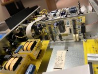
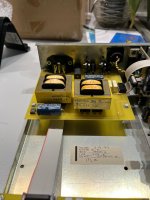
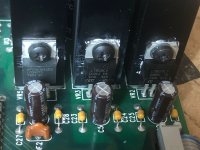
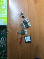
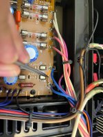
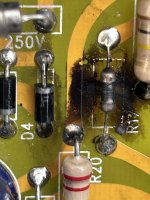
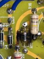
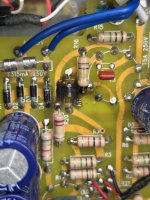
After finalizing the overall design, simulations are used to select specific components and determine resistor and capacitor values, followed by circuit board manufacturing for validation and iteration to achieve the initial design goals.
The Σ-Δ (Sigma-Delta) modulation method was chosen for the following reasons:
1,A fixed-frequency PWM modulator has almost zero Power Supply Rejection Ratio(PSRR) in its output stage, meaning it has no ability to suppress power noise. This creates significant challenges for power supply design, as any noise from the power supply directly converts into audio noise and reaches the headphones. In contrast, the Σ-Δ modulator offers some level of power supply noise rejection, greatly reducing the burden on power supply design.
2,Fixed-frequency PWM modulators use a standard triangular wave (blue waveform in Figure 1(a)), which contains a lot of high-frequency components. However, the integrator-generated waveforms from multi-stage integrators (green waveform in Figure 1(a)) resemble a triangular shape but with fewer high-frequency components and faster high-frequency roll-off (as shown in Figure 1(b), with blue representing the standard triangular wave's spectrum and green representing the multi-stage integrator waveform's spectrum). In an amplifier with the same bandwidth, the multi-stage integrator waveform results in lower distortion, and the PDM modulation signal's edge jitter (rise and fall times) is smaller, leading to overall lower noise and distortion of audio signal.
(a) (b)
Figure 1, Triangle Wave, Higher-Order Integral Wave, and Their Spectrum
3,The Σ-Δ modulator can use a differential integrator circuit, which outputs a pair of equal-amplitude, opposite-polarity integrator waveforms (see Figure 2(b)) to the comparator. In contrast, the fixed-frequency PWM modulator sends a triangular wave and input signal to the comparator (Figure 2(a) shows the comparator input waveform of the fixed-frequency PWM modulator). It's clear that the slope (rate of change) at the intersection points of these two sets of input waveforms differs significantly. The differential integrator waveforms have a much steeper slope at the intersection points compared to the PWM modulator’s waveforms. This means that for the same noise level, the edge jitter of the comparator output is smaller, thus improving the overall amplifier performance. Attentive readers might have figured out that the slope at the signal crossover points of the higher-order integrator waveform should be much steeper than that of the standard triangular wave, which could be one of the reasons why the higher-order integrator performs better than the standard triangular wave.


(a) (b)
Figure 2, Comparator Input Signals of PWM and PDM Modulators
4,Compared to fixed-frequency PWM modulators, Σ-Δ modulators offer greater flexibility and room for improvement in design. For example, a Schmitt trigger mechanism can be added to the comparator in a Σ-Δ modulator to improve the stability of the PDM pulse waveform edges.
The discussion so far has focused on reducing edge jitter in the PDM pulse signal. In Class D amplifiers, the pulse signal is central to the entire system; only precise pulses can result in low noise and low THD distortion. The edges of these pulses are crucial. If edge jitter is unrelated to the input signal, it generates noise, which, while having a smaller effect on distortion, can increase the amplifier’s background noise. If edge jitter is related to the input signal—such as when the triangular wave lacks linearity—the jitter (early or late edges) will correlate with the input signal amplitude, causing nonlinear distortion and resulting in higher THD.
Through the improvements discussed above, Σ-Δ modulation can potentially achieve lower distortion. The next step is to compare performance through simulation to select different components and parameters. This is a complex and tedious process, as components interact with each other, and changes to one typically require adjustments to related parameters. I'll use a key example to explain this further.
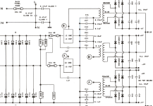
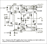
The precision of the modulated pulse signal comes from the accuracy of the multi-order integrator signals. The amplitude and frequency of these integrator waveforms are affected by many factors, such as the zero and pole distribution in the integrator network, the depth of the Schmitt trigger in the comparator, and the oscillation control resistor. For simplicity, Figure 3 shows a basic schematic of a multi-order half-bridge Σ-Δ modulator with a Schmitt trigger. The ratio of the Schmitt trigger resistor influences the modulation frequency, and the equivalent capacitance of the high-order integrator also affects the modulation frequency. These factors further shape the integrator waveform and its amplitude.
The accuracy of the integrator waveform has already been analyzed, but its amplitude is equally important, requiring a balance between the output capability of the integrator and the performance of the comparator. In general, a larger signal fed into the comparator results in more precise outputs, but an overly large output from the integrator can cause signal distortion.
Figure 3, Multistage Half-Bridge Sigma-Delta Modulator with Schmitt Trigger Mechanism
The second important aspect is the selection of the output stage, where the industry has reached a consensus: when cost requirements are not stringent, a full-bridge configuration is typically used. The advantages of the full-bridge mode include the ability to partially cancel even-order harmonics and suppress the back current of the output filter inductor, effectively reducing the power supply fluctuations in the output stage. This is particularly beneficial for Class D amplifiers with poor power supply rejection ratio (PSRR).
The output filter is also critical, especially for Class D amplifiers using PDM modulation. Since this design uses a modulation frequency above 2 MHz, there is more flexibility in choosing the low-pass filter’s cutoff frequency. This brings significant benefits: first, a higher cutoff frequency can be chosen, so the frequency response changes with different loads won't significantly impact the amplifier’s effective bandwidth. Second, since smaller inductors are used, they provide better linearity at the same size, reducing the distortion impact on the amplifier. During simulation, it was also observed that a multi-order output filter could reduce in-band noise, although there is no theoretical explanation for this yet. I welcome any interested parties to discuss this further.
The power supply solution is equally important. This design uses a single 3000mAh lithium battery, so a step-up boost converter is required. A major issue is that the amplifier operates at over 2 MHz, which is much higher than the frequency of commonly available boost converters. During a single PWM cycle, the supply voltage may drop due to the amplifier’s high current draw, which even the best boost chips struggle to handle in such cases.
After multiple experiments, both the pre-amp and output stages ended up using a two-stage single power supply solution. The pre-amp power (for the integrator and comparator) uses a combination of a boost circuit and a Class A power supply. The Class A supply uses a high-precision reference regulator with voltage accuracy of 0.1% and power supply noise as low as a few microvolts. Additionally, the midpoint reference voltage uses the same precision reference chip, not only improving voltage accuracy but also ensuring the integrator circuit operates symmetrically, optimizing open-loop performance.
Originally, I planned to use the same design for the output stage power supply, but due to the need to drive headphones with varying impedance and sensitivity, the Class A power supply’s efficiency was too low, which affected battery life. In the end, I chose a step-up circuit combined with a high-precision, high-current LDO and large capacitors for the output stage.
Interestingly, switching from a Class A supply to an LDO + large capacitors for the output stage resulted in virtually no subjective change in sound quality. However, changing the pre-amp from an LDO to a Class A power supply led to a significant improvement in sound. The high frequencies became more transparent, the low frequencies were stronger and more extended, and the soundstage was more stable. This change was quite noticeable, without the need for careful listening. Could this be due to the higher precision in both supply and bias voltages? I would love to hear thoughts from those interested in discussing this. The first version of the pre-amp, which was discarded, used a voltage divider for the bias reference, as shown in Figure 4, with resistor accuracy of 0.1%.
Figure 4, Circuit for Generating the Bias Voltage in the Integrator
There are many other crucial details in the amplifier design and debugging process that cannot be overlooked, and I will discuss them further in appropriate contexts.
Figure 5 shows the Spice simulation results for the background noise. Within an effective bandwidth of 35 kHz, the highest background noise is as low as -170 dBV, with the low-frequency section reaching nearly -180 dBV.
Figure 5,Zero Input Circuit Configuration (Background Noise) Simulation Results
Figure 6 shows the simulation results with a 1kHz input signal. No harmonic distortion related to the 1kHz frequency was observed. However, compared to the zero-input results in Figure 5, the background noise increased by about 10dB, reaching approximately -170dBV. This frequency-independent distortion is a typical occurrence in such circuits.
Figure 6, Single Sine Wave Input Circuit Configuration Simulation Results
Figure 7 presents the amplifier simulation results based on the previous discussions. The modulation frequency is around 2.3 MHz, with an input signal peak-to-peak value of about 196 mV and an output peak-to-peak value of around 4000 mV, resulting in an overall gain of approximately 26 dB. The input signal consists of three frequencies: 500 Hz, 5 kHz, and 20 kHz. The amplifier's background noise level is about -167 dBV, which is 3 dB higher than the -170 dBV observed in the 1 kHz sine wave test shown in Figure 6, likely due to frequency-independent distortion causing this noise floor increase.
During the simulation, it was observed that different multi-stage integrator network configurations affect the spectral characteristics of frequency-independent distortion. By adjusting the integrator network, it is possible to reduce low-frequency distortion at the cost of increasing high-frequency distortion. In this design, I chose to balance the frequency-independent distortion across the spectrum, leading to a flat noise floor.
In reality, there are other approaches. One could adjust the integrator network to minimize the total or weighted power of frequency-independent noise within the effective bandwidth, without prioritizing flatness. My choice for a flat noise floor was based on the fact that amplifiers typically exhibit more distortion in high frequencies compared to low frequencies, whether it is frequency-dependent or independent. A DIY amplifier with a flat noise floor might offer a different subjective listening experience.
Given the multi-frequency input, the amplifier's total distortion is primarily composed of harmonic and intermodulation distortion. The simulation results show that the highest harmonic distortion reaches about -156 dBV, with the minimum signal-to-harmonic ratio being 152 dB. These results demonstrate excellent noise suppression and distortion control, achieving the expected high-performance standards, at least based on the simulation outcomes.
Figure 7,Multi-Sine Wave Input Circuit Configuration Simulation Results
The following lists the different distortion frequencies and their amplitudes generated from the simulation, for reference by those interested:
- 1.5 kHz, -164.3 dBV
- 4 kHz, -159.5 dBV
- 9.5 kHz, -159.1 dBV
- 10 kHz, -160.7 dBV
- 10.5 kHz, -160.2 dBV
- 14.5 kHz, -157 dBV
- 15.5 kHz, -157.0 dBV
- 19 kHz, -157.1 dBV
Overall, the simulation results show extremely low distortion, with distortion in the high-frequency range being about 5-7 dB higher than in the low-frequency range. It's noteworthy that there is a distortion point at 10 kHz, which corresponds to the second harmonic of the 5 kHz signal. However, the distortion values at these points are so low that the specific values are not very meaningful for further analysis —they are all well beyond the range of human hearing.
For those who might not be familiar with these simulation figures and find them hard to interpret, it's worth noting that if you were to input a true 24-bit audio source into the amplifier, the output would be virtually undistorted. The harmonic distortion is more than 7 dB lower than the 24-bit quantization noise, making it effectively distortion-free.
In addition, I added negative feedback to the circuit from Figure 7 and adjusted the overall gain to 20 dB, 6 dB lower than without feedback. Observing the results in Figure 8, no frequency-dependent harmonics were observed, but the overall noise floor increased by about 1 dB compared to the no-feedback case.
This phenomenon may differ from traditional Class B amplifiers. Class D amplifiers, due to their modulation frequency, generate out-of-band noise. When negative feedback is introduced, this out-of-band noise can also be fed back to the input. While negative feedback effectively suppresses harmonic distortion caused by nonlinearity, the feedback of out-of-band noise may increase frequency-independent distortion, thus raising the overall noise floor.
Although this analysis partially explains the rise in noise floor, it has not been rigorously validated and is provided for reference only. If I gather further experimental data or validation, I will share it separately in the future.
Figure 8, Simulation Results of Multi-Sine Wave Input Circuit Scheme with Global Feedback
Additionally, when observing the operating frequency of the amplifier, it becomes apparent that as the peak value of the input signal increases, the divergence of the main frequency enhances, while the peak itself becomes lower. This phenomenon is a characteristic of the sigma-delta self-oscillation architecture, providing significant advantages in electromagnetic compatibility (EMC). Since the self-oscillation frequency is not fixed, it dynamically changes under different load and signal conditions, dispersing EMI (electromagnetic interference) energy rather than concentrating it at a specific frequency. This reduces interference with other devices, making sigma-delta amplifiers relatively superior in EMC performance in practical applications.
The following text is excerpted from "Audio Power AMP Design Handbook 4th edition" by Douglas Self, which discusses the increasing distortion characteristics of traditional Class B amplifiers at higher frequencies. Although this book was published in 2006, and advancements in technology may have significantly improved the high-frequency distortion characteristics of current amplifiers, this fundamental principle still holds unless there are breakthrough developments.
From the simulation results, Class D amplifiers also adhere to this pattern, but their high-frequency distortion is only a few dB higher than the low-frequency distortion. Given the overall low distortion rates, this difference can generally be ignored.
Another noteworthy aspect is that the amplifier's phase response tends to be linear. As we know, the human ear is not very sensitive to phase response in sound. Therefore, it raises an interesting question: do linear-phase amplifiers produce different subjective listening experiences? If anyone has personal experiences or insights on this, it would be great to share and discuss!
Based on a simple calculation of the simulated distortion effects, the amplifier's THD value can reach approximately 0.0000025% with the minimal SNR is 152dB. Considering that the harmonic components are several dB above the noise floor, the THD+N value should be in the same range. This simulation result seems almost unrealistically good, so I conducted multiple verification simulations and cross-checked with actual test results, ultimately confirming that the simulation results have a certain degree of credibility. The verification approach was as follows:
- Device SPICE Model Verification: Each device's SPICE model was individually verified by building its recommended test circuit using the model and comparing the results with those provided by the manufacturer. The simulation results matched the manufacturer's data closely, confirming the accuracy of the models used.
- Comparison of Simulation and Measured Parameters: Key parameters of the fabricated circuit (such as the amplitude and shape of the integral waveform, the amplifier's oscillation frequency, and gain) were measured and compared with simulation results, with discrepancies generally kept within 10%. This directly demonstrates the reliability of the simulated circuit.
However, due to the lack of sufficiently high-precision instruments, I was unable to directly verify the noise floor and THD distortion values through measurement. This limitation makes the validation of these performance metrics in the simulation somewhat lacking, but overall, the verification results still hold reference value.
Of course, the performance results from the simulation represent only a theoretical upper limit; the actual amplifier's performance may degrade to varying degrees due to various factors. A good simulation result is merely a starting point, and the process of building the amplifier is essentially a struggle against these degradation factors.
Writing the threads has been particularly challenging for me. I’ve tried to clearly describe the simulation conditions at the time, but the reality is far more complex than what I've expressed here. If there are any unclear or incorrect points, I welcome further discussion. For now, I will share the results of my two major version of DIY AMP and some subjective listening experiences, so stay tuned!


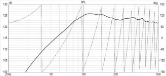
 (see VituixCAD FRD)
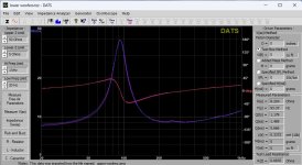