Greetings. I just carefully designed and built a beautiful set of speakers, but when I measure the woofer low-end response, it's very far from the calculated response. Here are the details.
I'm confused and frustrated. Any advice would be helpful.
View attachment 1358224
- I'm using pairs of CSS WR125 drivers. I got their T/S parameters from the pdf file included in the documents. (see CSS-FR125S-wr125-dimensions)
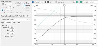
- I enter these parameters into VituixCAD. and modeled a closed box with Qtc of 0.8. It said 18.6 liters for 2 drivers in parallel. (see VituixCAD showing 18.6 liters)
- So I build a cabinet with 18.1 liters and stuff it with the recommended amount of Polyfill - 1lb/ft^3 I think. I mount the 2 drivers in parallel.
- I made close-mic (nearfield) measurements with the Arta software. I chose one of the two woofers, but kept them both in parallel. I've got a calibrated microphone from Dayton Audio, a nice external power supply with synchronized clocks for the input and output, a nice LM3886 amplifier etc . . Not sure of where to put the microphone, I made several measurements of one woofer from 0.5cm to 5.0 cm from the phase plug, as well as an off-axis measurement. They were all very similar after normalizing absolute SPL levels, so microphone placement is not an issue.
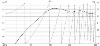
- The FRD data shows a big peak above 100Hz and a 14dB/octave slope!
 (see VituixCAD FRD)
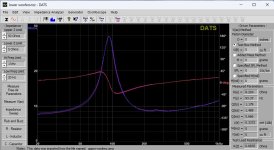
 - I also measure the impedance (of both drivers in parallel) with the Dayton DATS V3. The result says my Qtc=1.18! (see snip of DATS data)
I'm confused and frustrated. Any advice would be helpful.
View attachment 1358224
Attachments
It could be the effect of a crossover, did you measure with crossover?
Crossover (reactive or resistive) parts will interact with the speaker's impedance peak and may create a response peak.
Crossover (reactive or resistive) parts will interact with the speaker's impedance peak and may create a response peak.
Looks good to me. After the baffle step, that bump will flatten. If you make flat nearfield response, then after baffle step there is not much left.
No crossover components.It could be the effect of a crossover, did you measure with crossover?
Crossover (reactive or resistive) parts will interact with the speaker's impedance peak and may create a response peak.
Yes, but I didn't save the files. I measured 4 WR125ST and 4 WR125STR and averaged each. This is the averages.Did you measure one raw woofer free air?
Much higher fs and qts, maybe the drivers need some breaking in?This is the averages.
A few. I was going to save the pics for when they are finished.Hi Byron,
Glad to see things are up and running.
Any pics of the speakers yet?
https://photos.google.com/photo/AF1QipMfLc9_cc39dPsuQsDWzCWKhvFZnpfb6e7YV1Fc
https://photos.google.com/photo/AF1QipMfLc9_cc39dPsuQsDWzCWKhvFZnpfb6e7YV1Fc
Attachments
Could that be the problem? I didn't break the drivers in at all. When I tested was the first time they ever had current going through them.Much higher fs and qts, maybe the drivers need some breaking in?
When I entertained those drivers, it was one of the few that I found didn't need break in time so much as warm up time. They really come in to their own after a half hour or so.
I am hoping those Swan's are a nice compliment.
Thanks for the pics, they look really good to this point.
I am hoping those Swan's are a nice compliment.
Thanks for the pics, they look really good to this point.
Not true. The 'unused' ones had a 24 hour 'on the bench' break in period when new but tbh, that is a while ago. I expect you will find the warm up is what will bring you happiness.When I tested was the first time they ever had current going through them.
I won't deny that the curves are different. But as an engineer I am telling you: if you want to compare graphs keep the scales equal. It won't make the graphs less unequal but at least you make a proper comparison.
Unless you have something very sophisticated, I think that most software uses a math model of a non-resonant box with one driver in it. You made a very long box with several drivers sharing the same volume. You can calculate the resonance of that chamber using Hornresp software. The drivers resonance, fs, is often higher than what is in the data sheet. I don't know why, but that has been the case for every woofer I have ever purchased. With use the resonance will drop. Studies have shown that when woofers are not used for a few months the resonance tends to go back up. What to do? Well it looks like you could try to segment the drivers into individual enclosures. It would also help to just stuff the segments with dense rockwool, lambswool or fiberglass batting to absorb the sound.
Member
Joined 2003
#1 says you got T/s from spec sheet. #6 says you measured impedance with DATS.Greetings. I just carefully designed and built a beautiful set of speakers, but when I measure the woofer low-end response, it's very far from the calculated response. Here are the details.
So I'm kinda' stumped, and hoping there's something wrong with my measurements. One thing I'm considering is that my cabinet is too tall and skinny. the cross-section is a trapezoid with a 5" baffle, an 11.75" back and 5.75" deep for a cross section area of 48in^2. Then it's 21.25" tall. Did I accidentally make a transmission line without an opening?
- I'm using pairs of CSS WR125 drivers. I got their T/S parameters from the pdf file included in the documents. (see CSS-FR125S-wr125-dimensions)
- I enter these parameters into VituixCAD. and modeled a closed box with Qtc of 0.8. It said 18.6 liters for 2 drivers in parallel. (see VituixCAD showing 18.6 liters)
- So I build a cabinet with 18.1 liters and stuff it with the recommended amount of Polyfill - 1lb/ft^3 I think. I mount the 2 drivers in parallel.
- I made close-mic (nearfield) measurements with the Arta software. I chose one of the two woofers, but kept them both in parallel. I've got a calibrated microphone from Dayton Audio, a nice external power supply with synchronized clocks for the input and output, a nice LM3886 amplifier etc . . Not sure of where to put the microphone, I made several measurements of one woofer from 0.5cm to 5.0 cm from the phase plug, as well as an off-axis measurement. They were all very similar after normalizing absolute SPL levels, so microphone placement is not an issue.
- The FRD data shows a big peak above 100Hz and a 14dB/octave slope!
(see VituixCAD FRD)
- I also measure the impedance (of both drivers in parallel) with the Dayton DATS V3. The result says my Qtc=1.18! (see snip of DATS data)
I'm confused and frustrated. Any advice would be helpful.
View attachment 1358224
If you have a DATS and a measurement mic, first step should be to throw spec PDF away. Use real measurements of your drivers for design. Measure complete T/S parameters with DATS. Best method would me to use added mass method, and run T/S calculations right in VituixCAD. For a speaker of this size, about 5g added mass should be all you need, but check that the measurement with added mass has a Fs decrease by at least 25%.
In VituixCAD T/S calculator, solve for "Extended Z" parameters for accurate impedance characterization. Within simulation of the cabinet with your measured T/S parameters, right click on the chart and select "show effect of impedance". Next, adjust Qa and Ql to some value other than 100 to simulate some fill and some leakage.
Example:
Now compare results again and see what it looks like.
Yes. I designed be box using the Manufacturer's specs. Once built, I used DATS to measure 2 drivers in parallel in the cabinet. I measured both top pair and bottom pair. They were identical, as they should be.#1 says you got T/s from spec sheet. #6 says you measured impedance with DATS.
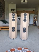
You can't see from the photos, but the box has 2 18.1 liter chambers, each with 2 woofers in it. that middle "brace" in the photo is a bulkhead separating the upper and lower chambers. The other 4 are just braces.You made a very long box with several drivers sharing the same volume.
Last edited:
Well, I have good news everyone. Last night I hooked up both speakers to my stereo system (without tweeters), and they sound fantastic! According to my measurements, I should get a boomy sound around 100Hz with nothing below that. NOPE! I didn't hear any boomy-ness, and the bass was surprisingly deep. So my current theory is that I did something wrong in my measurement. And my best guess is that it has something to do with:
My only challenge now is designing the low pass filter for the lower pair. It's going to be a 2.5-way system. I'll break them in for a few days and re-measure impedance and nearfield and see where I am.
Thank you everyone for your advice!
- measuring 2 drivers in parallel when the software is expecting 1 driver, for both the frequency response and impedance.
- measuring drivers which had not been broken in. I know Cal (the gentleman who sold me these beauties) broke them in for 24 hrs, but that was a "while ago".
My only challenge now is designing the low pass filter for the lower pair. It's going to be a 2.5-way system. I'll break them in for a few days and re-measure impedance and nearfield and see where I am.
Thank you everyone for your advice!
Great!and they sound fantastic!
They do look wonderful!
- Home
- Design & Build
- Software Tools
- Measured woofer response is way off from calculated response.


