Hello people,
I have a Quad 303 amp ( ser# 4890 - so an early one!).
I was given it by a friend as a non worker - so after a couple of weeks of tinkering I have finally got it back into some form of life.
I have replaced the electrolytics and a couple of burnt resistors and the trim pots - all the transistors and diodes are original.
The amp turns on and i am measuring 67v between pins 1&9 and 33.5v between pins 5&9. The quiescent on the RIGHT channel is at 9mA via RV101 but i cant get the quiescent on LEFT channel to change from 85mA irrelevant of which way i turn the POT.
I have methodically tried tracing the issue but I have run out of ideas! - I could 'cheat ' and just replace components for the sake of it but that takes the fun away - I will get to the bottom of this but I just need help!
Electronics is not my job - I just enjoy it!!!
any help/pointers greatly appreciated!
regards
Mark
I would begin by measuring the voltage between the base of the two driver transistors and seeing what range of adjustment you have. Compare good and bad channels. I would expect around 1.5 volt and that voltage should certainly change with the pot.
Also do not discount instability, particularly if semiconductors have been replaced. A scope check would show that in seconds.
Also do not discount instability, particularly if semiconductors have been replaced. A scope check would show that in seconds.
Apologies for not answering - work got in the way!!
@JS - mine is the early model - below #11500 ( 4980) -
However, just come back to this this afternoon - not touched it since 7th Jan - turned it on and my light bulb limiter went crazy - turned it off immediately.
after measuring Tr200 and Tr201 and Tr 3 all looked well - the Zener is in one piece as is the diode - only issue I found was R201 was measuring 40k! ( out of circuit) - replaced this and tried again.
Same issue - light bulb went crazy.
detached both driver boards ( one at a time) -still a problem with either board connected. Both boards disconnected light stays off.
I'm getting 69v across C2/C3 - but only getting 57v on the output of regulator board - and there is only +/- 4v change when RV200 is turned.
I'm going to go through everything again later - just baffled what changed!!
as always, suggestions appreciated!
Mark
Hi Mooly - thanks for this -
Odd thing happened.
I checked every component in the reg board again - all seemed fine, then i decided to put back the original RV200 pot - guess what? - I get full adjustable voltage and can set it to 67V!!!!!
The new pot is defo 4K7 and it measures good across the whole turn - baffled is not the word!!!
Going to find time to reconnect the amp boards this morning.
regards
Mark
After checking - and checking again I put one of the boards back.
The 67v has now appeared between 1 & 9 and i now have 33.5v between 5 & 9.
What i dont have is any quiescent or control from RV101 -
After checking EVERY comoponent, I found TR105 short circuit ,R115 open circuit and R118 open circuit.
Before repairing this board, I tried the other board - again got all the voltages in all the right places, but again no current or adjust via RV101 - checked EVERY component on this board expecting to find the same issues as before, but everything checked out ok -
getting a bit confused here!
Mark
Are the PCB tracks intact?
If you had a shorted TR105 is the associated power device functioning? That may be O/C and not responding. Though the power devices are connected with flying leads.
Mostly, though, power devices have gone short too, on failures I've seen, but they may have gone O/C if they use bond wires.
If you had a shorted TR105 is the associated power device functioning? That may be O/C and not responding. Though the power devices are connected with flying leads.
Mostly, though, power devices have gone short too, on failures I've seen, but they may have gone O/C if they use bond wires.
Last edited:
Are you sure the transistor was really short circuit?
You have to check it out of circuit and using the appropriate ranges on the meter. Anything else in a configuration like this may give results that look like a short when there in fact isn't.
Have you tried what I suggested in post #3 and measured the voltage between the base of the drivers. Also see what range you get as you turn the preset?
If any of the original semiconductors (particularly the drivers and those diodes) have been replaced then you may be chasing a non existent fault that is an effect of differing device characteristics.
So I found a slight issue why I wasn't reading quiescent....the fuse had blown on the mA setting of my DMM!!.
TR105 is defo short C-E, checked out of circuit.
Voltage between base of drivers is 1.47v and can be adjusted ( RV101) to 1.56v.
So, all of the semiconductors are original in both boards - just a couple of resistors and all electrolytics have been changed.
What I am seeing now is correct voltages but a start current of 95mA which gradually creeps up - RV101 does have an effect but obviously current is way too high.
I will swap TR105 to the other board and see if that shows same symptoms - I have ordered replacement for TR105, should be here later today.
The meter fuse I can understand ")
You are going to have to be clear on the time scale of all this. You said earlier that you had 33 volts between 5 and 9 on the board and then said you found TR105 was short.
If TR105 were short you could not get 33 volts on the midpoint, the failed transistor would turn on the upper NPN output fully and just put supply voltage on the midpoint and/or do further damage as well.
I'm not trying to catch you out its just very important in the diagnosis.
The voltage see between the base of the two drivers is about right but also right on the upper limits of that needed for just a few milliamps bias current.
You could try as a test linking out just one of the diodes MR103 or MR104 and seeing if the current falls away.
If incorrect bias is the only issue then the amp should play music normally and with no obvious issues (apart from excess heat). That could be a good test to see whether any other issues might be lurking.
You are going to have to be clear on the time scale of all this. You said earlier that you had 33 volts between 5 and 9 on the board and then said you found TR105 was short.
If TR105 were short you could not get 33 volts on the midpoint, the failed transistor would turn on the upper NPN output fully and just put supply voltage on the midpoint and/or do further damage as well.
I'm not trying to catch you out
its just very important in the diagnosis.The voltage see between the base of the two drivers is about right but also right on the upper limits of that needed for just a few milliamps bias current.
You could try as a test linking out just one of the diodes MR103 or MR104 and seeing if the current falls away.
If incorrect bias is the only issue then the amp should play music normally and with no obvious issues (apart from excess heat). That could be a good test to see whether any other issues might be lurking.
Hi Mooly - yeah apologies this is me flitting from 1 board to another and not actually telling you which board I'm referring to!!
So the board that is complete does pass audio - there is a slight hum, from experience I would say around 50-60 Hz. quiescent eventually tops out at 185mA, this is with RV101 set to minimum - 67v and 33.5V are constant.
I have now 'pinched' TR105 from this 'good' board and put it in the other board - again this passes audio, with the same hum - but only half the level. Also quiescent tops out at 185mA with RV101 at minimum.
I am just waiting for the replacement for TR105 with is not a 38496 but 2N5322 - will this be ok on its own or should I replace TR106 with 2N5320?
I will look at why this board is low level when I can get both boards running together to do comparisons.
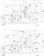
I did see a drawing a while ago which had voltages at various points on the board but can't seem to find it now!
So the board that is complete does pass audio - there is a slight hum, from experience I would say around 50-60 Hz. quiescent eventually tops out at 185mA, this is with RV101 set to minimum - 67v and 33.5V are constant.
I have now 'pinched' TR105 from this 'good' board and put it in the other board - again this passes audio, with the same hum - but only half the level. Also quiescent tops out at 185mA with RV101 at minimum.
I am just waiting for the replacement for TR105 with is not a 38496 but 2N5322 - will this be ok on its own or should I replace TR106 with 2N5320?
I will look at why this board is low level when I can get both boards running together to do comparisons.
I did see a drawing a while ago which had voltages at various points on the board but can't seem to find it now!
You could try as a test linking out just one of the diodes MR103 or MR104 and seeing if the current falls away.
So this results in voltage between bases is 0.75V and the quiescent starts off at 20mA and then plummets down to ZERO in around 3 seconds - this is the smae for both MR103 and MR104.
Interesting... so both boards do in fact work at a basic level.
The hum is something that shouldn't be there and so I wonder if there is some issue with the regulator.
The 303 circuit and its bias current is very very sensitive to small changes in supply voltage where even say a 3 volt increase or 3 a volt decrease on that 67 volt rail would swing the bias current by a big amount.
That doesn't mean its a poor design, it just means the regulator is a uniquely important piece of the whole amp.
Also any change in supply voltage reflects as a change in the midpoint voltage at the amp output and so by implication any ripple on the rail would also find its way to the speaker output.
Ideally you need to not just monitor the voltage of the 67v rail but also look at it with a scope. Everything up to now is seeming to point toward something common to both channels like a regulator fault.
So this results in voltage between bases is 0.75V and the quiescent starts off at 20mA and then plummets down to ZERO in around 3 seconds - this is the smae for both MR103 and MR104.
And this result is what was expected really, the bias should stabilise at zero or very near to that point. Again this shows things with the amp boards are working as expected.
I'm not familiar with the 2N devices you mention but they look quite an 'oldie' and should be OK spec wise. Ideally the NPN/PNP pair should be matched... and then as to stability... probably would be OK but these output triples can be a bit finnicky.
You will only know by trying, it can't really be second guessed. If you only have the one of the pair then just fit that and test it all and see how it behaves.
This may not be of much help, I have just spent some time repairing a Quad 303, one channel ran very hot and this was down to a faulty TR103, e/c short and its emitter resistor open circuit. The bottom part of the small heatsink which is screwed to the pcb was loose on one side probably from new, replacing TR103 and its resistor restored operation. The other channel could not be adjusted to the midpoint and sat about 5V. After a lot of investigation I found that R104 in the emitter of TR100 had changed in value from 22k to 40k. I dont do many 303s but I fix a lot of 405s and have had a few random resistor failures but this is the first one I have had that doubled in value. It was a help that I had the second channel working but not much.
Stuart
Stuart
The 2N5320 and 2N5322 are old RCA devices rated at 75V Vceo, and were 2A 10W medium power drivers. Obviously old Q303's need TO-5/TO-39 replacements for pin compatibility (and heatsink fixture). They are largely obsolete, but may be available from some after market suppliers/manufacturers, at a price.
I think 2N3019/2N4033 are more readily available (Farnell had them last time I looked) and may work too.
I agree with Mooly's suggestion that the PSU may be in need of attention. Perhaps even the main filter caps as old electros can go high impedance.
BD139 and BD140 could be used as replacements but the pins and packaging would need modding the heatsink etc.
For the PSU any dead transistors or devices will need to be 100V rated. A suitable replacement regulator might be the MJ15003 and a driver the 2N5682 (120V), which was also available at Farnell last time I looked, and the 2n5680PNP which could also be used for the amplifier drivers.
So the 2N5320 &22 finally arrived.
Installed both in the same board - managed to set min rail voltage at 33V - but quiescent is showing 0.00, checked the quiescent on the other board and it settles at 185mA (as before) - revert back to the 2N5320/22 board and shows no current. However both channels pass audio - albeit the 2N5320/22 sounds a bit 'sawtooth' when injected with 1k sinewave.
The original board had a very low level, so I started to scope it to find where the signal had gone - when i got to BASE of TR100 there was a 'crack' and the audio came back to the same volume as the other board. Unfortunately I don't have a BC154 to hand so I can't change it out.
- Home
- Amplifiers
- Solid State
- Quad 303 quiescent