I'm looking for a schematic for a second order high pass filter with the ability to vary the Q from say 0.707 to 2.8 or so. Playing around with an update to the JBL BX63/BX63A. I know I can do it with rotary switches and fixed resistors, but I'd prefer to use a dual gang potentiometer.

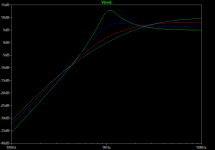
From my calculations with C1=C2= 0.22uF, I'd need R1 to vary from 20k to 5.1k while R2 varies from 39k to 150k for Qs from 0.707 to 2.75.
I've searched and not found anything, maybe I'm not using the correct keywords?
From my calculations with C1=C2= 0.22uF, I'd need R1 to vary from 20k to 5.1k while R2 varies from 39k to 150k for Qs from 0.707 to 2.75.
I've searched and not found anything, maybe I'm not using the correct keywords?
I have done it long ago, the easiest way is changing the structure of the OpAmp to have variable gain, every other thing remains the same.
I cannot promise it; but I can look this weekend for the simulations I did using LEAP at that time, they should be stored somewhere.
If you use any other simulation program change the buffer for a non-inverting amp with variable gain between +1 (buffer) and something like +2 or +3.
I cannot promise it; but I can look this weekend for the simulations I did using LEAP at that time, they should be stored somewhere.
If you use any other simulation program change the buffer for a non-inverting amp with variable gain between +1 (buffer) and something like +2 or +3.

Yes, this is the straight-forward way. Design the filter for the minimum Q with Gain=1, then by increasing the gain the Q goes up.so that the frequency is correctI have done it long ago, the easiest way is changing the structure of the OpAmp to have variable gain, every other thing remains the same.
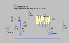
Version which taps off the output after the filter cell, to avoid the gain to appear:
R4 must be trimmed to get the same maximum gains across channels because potentiometer total resistance usually has high tolerance. R3 is a linear pot used as variable resistor here.
Of course, the gain is still there inside the circuit and has to be dealt with. Too large input levels will cause clipping.
Here is another variant, using only a single OpAmp and reducing the risk of clipping. The cost is doubled number of caps and resistors (which all need to be low tolerance):
Because potentiometer values are restricted and also have large tolerance, a helper resistor Rx is used in parallel to linear pot R3 to get the exact value for a given target frequency. Make sure it doesn't calculate as negative, if so you need to go to the next standard pot value (like from 10k to 20k).
Last edited:

- Home
- Source & Line
- Analog Line Level
- Variable Q high pass filter schematic?