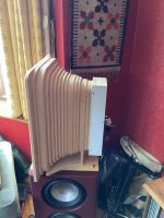
Dayton Reference RS270-8 10" Woofers (almost new in original boxes)

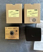
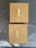
For sale: One pair, Dayton RS270-8 10" woofers. Woofers have been briefly mounted to test, but have less than 10 hours of use.

dasyton_reference_10s.jpg


One of them has a cone blemish- the other is in cosmetic perfect condition. Spiders are perfectly flat (no cone sag).

dayton_reference_10_blemish.jpg


Selling for $130.00 for the pair, plus shipping.

Would accept up to two Dayton Audio DCS165-4 6.5" subwoofer drivers and/or up to four Dayton Epique E180HE 7" passive radiators in partial or total trade toward these.

Located in Kennesaw GA. Local pickup definitely available!

If replying to this- please also send an email to gwaters@inbox.com, as I don't get to check in here as much as I used to...

Thanks!

Regards,
Gordon.

Intro and DIY

Hello folks,

I've been an audiophile and electronics tinkerer for over 40 years. Current I've begun my journey as a Pass Labs owner with the purchase of a X150.8 power amp. It's partnered with a BAT VK-80 preamp and drives a set of Zu Definition 3 speakers.

My drive to join the forum is also due to my NAD 3020A restoration project, and would always love input and help.

Neil

For Sale High-end DIY speaker project (Eclipse 1238R, Madisound 8252R, Focal 7V313, SEAS 27TFFC, enclosures

For sale: Very high-end DIY speaker system, I helped design and build about 20 years ago. It is a project- as it will require some re-building.

madisound_custom_triamp_front.jpg


This system is four-way, tri-amped, with passive crossovers (included) between the midrange and tweeter. Drivers per channel are: tweeter: 1- SEAS 27TFFC, midrange: 1- Focal 7V313, mid-woofers: 4- Madisound 8252R 8", subwoofers: 2- Eclipse W1238R.

madisound_custom_eclipse_w1238r_subwoofers.jpg


The cabinets for the mid/tweeter and midbasses are Woodstyle, from Madisound. The mid-high cabinets are sealed, and the midbass cabinets have one Dynaudio aperiodic Variovent in the rear of each cabinet. The mid-tweeter cabinets are in good shape, including grills, but the midbass cabinets will require some repair, as there is some damage to the plinths of the cabinets. The cabinets themselves are in good shape, save for one missing grill- but the plinths have gotten slightly wet in storage, and will need some remediation. The cabinets for the subwoofers were built-into the wall of the original installation- and were not save-able, when this system was removed. I do have the specs for the subwoofer cabinets.

This system, as mentioned, was tri-amped. We originally used a Madisound Sledgehammer 3-way active crossover and a couple of four-band parametric EQs on the bass and midbass- but, all of this function could be much more easily accomplished now, by something like a DBX Driverack. That's what I would recommend, wholeheartedly. I can give the buyer a good starting point for the crossover settings in the Driverack (active crossover points of roughly 50Hz and 400Hz). The original passive crossovers (2.6KHz) between midrange and tweeters are also provided.

I don't know of any practical way to ship this- it's available in the northern Atlanta GA USA area (I'm in Kennesaw GA, but can drive to meet within reason- I have a pickup truck with covered camper shell).

Asking $600 for the lot.

This, frankly, was one of the finest audio systems I have personally encountered anywhere- and that includes very high-end systems I have worked with, that have price tags of into the seven-digit-dollar amounts. I would really enjoy having someone put it back into use...

Thanks!

Regards,
Gordon.

For Sale Amber 3501a Audio Distortion and Noise Measuring System

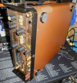
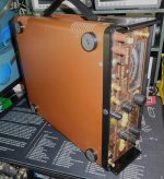
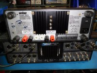
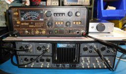
This is a really nice condition Amber 3501a that I bought a few years back to fill a gap while soing some maintenance on my other analyzers. The previous owner adapted this unit for his convenience when working in the field and at his shop on audio amplifiers. He changed the BNC generator output jack to an RCA jack, and added banana jacks for easy hookup of amplifier outputs. To switch between channels for taking measurements, he changed the front grounded/ungrounded input switch to switch between banana jacks (Input 1 and Input 2).

Here it is testing a buffer/preamp with very low output showing good sensitivity. I've used it for testing a few Adcom amps and it worked well, but as you can see from the unit beneath the Amber, I've moved into a different type of analyzer, and still have my early HP analyzers, so this is ready to move to the next person who wants a quick and easy way of testing functionality and performance without going into a more expensive system, or a more fiddly/time consuming approach like a soundcard and REW. Actually, I have those systems as well, and each has its own place. I find these self-contained distortion analyzers to be best for initial function/performance testing of units I'm evaluating prior to and after repairs.

When I bought it I cleaned all the rotary switches and board connections, inspected the boards and terminations, tightened various fasteners, and re-painted the front corner brackets.

How about $350 plus shipping and PP fees (CONUS only, please)? I can provide two PDF manuals for the buyer - the slightly different 3501 and for this 3501a. Thank you.

gktaudio_Amber3501A-2.jpg

gktaudio_Amber3501A-6.jpggktaudio_Amber3501A-5.jpggktaudio_Amber3501A-4.jpggktaudio_Amber3501A-3.jpggktaudio_Amber3501A-1.jpg

Best LDR for Sound Technology ST 17xx gear

Since there is little mentioned on the 'net re Sound Technology gear, perhaps it would be a good idea for those who have successfully repaired their gear to list the LDRs used along with any mods they have made to the circuit(s). Both in the Oscillator & Analyzer sections.
As a folllow up, they can comment on their findings. In addition, it would be helpful to establish a listing of results using different LDRs in different locations on the analyzer board.
ANALYZER BOARD
U205
U206
U207
U208

U7 (OSCILLATOR board)

The 17xx models share similar LDR circuits.

Whammy Custom PCB + Dual Mono PSU + Muses 72320 Vol Control

Another day, another finding,

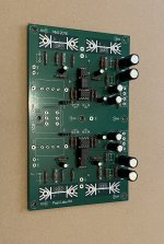
for sale is a set of custom PCBs for Wayne Colburn's Whammy, just a different approach (and a bit better sounding as I listened to about 3 versions of it). Designer of the set is a very professional DIYAudio member who puts a lot of passion into his routings and PCB making. The special thing is, you can put the Amplifier backpack on the PSU with appropriate Spacers and thus fit it into a 3U Galaxy Case from ModuShop (230x280), by using L-shaped aluminum heatspreads you can dissipate the output transistor heat directly to case without the need of a dedicated heatsink. The other thing making it special is the PSU (or UPS how the designer called it). It's a dual mono cap multiplier with HF and LF filters, thus very silent ;-). The amp board is nearly fully stuffed, only 4 resistors and a few caps missing. Stuffed with original BB OPA604. The muses vol. Control can be directly supplied by the PSU and does not need any special PSU

Consists of:
  • Whammy Board nearly fully assembled
  • A set of nicely matched 2SK2013 / 2SJ313 Output Transistors
  • Dual Mono PSU cap mulitplier PSU
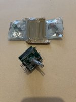
  • Muses 72320 Vol. Attenuator

I paid a total of around 230€ for everything,
asking 200€ + shipping + PP fees.


IMG_6971.jpegIMG_6972.jpegIMG_6970.jpeg

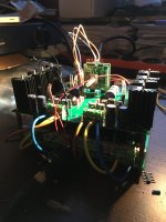
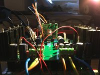
A built variant on bench for testing before it went into the enclosure (I know its dark pictures, just you get an image of how its backpacked).


IMG_1453.JPGIMG_1454.JPGIMG_1455.JPG

NJW Symasym - potential GB Interest

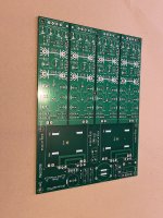
This will probably the last chance to get Rudi_ratlos latest iteration of Symasym boards as it will also be one of my last group buys for this. It's a great sounding amp, check on Forums for more information about it.

It's the latest version with 2 pairs of NJW output transistors. houses a speaker protect circuit (that does not have to be populated, but why wouldn't you). Board size is about 215x95mm. The board shares the option to power the front end of the circuit with a dedicated PSU by setting jumpers.

Price will depend highly on several factors as:

  • Number of interested builders
  • 1,6 / 2mm PCB
  • Min. is HASL-lead free
  • PCB color ;-)

I ran it through several well known PCB manufacturers and I came to about 14-15$ for a single board, not including taxes.

Please share your thoughts and interest that way. If enough people are interested, I will quote for the most requested.

#1 DIYAudio Name / Country / Qty of PCBs / Color (Green / Black / Red / something else) / Thickness (1.6 or 2mm) / HASL-Lead free or ENIG


Bildschirmfoto 2024-09-09 um 10.09.05.png
  • Like
Reactions: platon.rado

Increased voltage supply forYamaha SC-02

I have one of these Yamaha SC-02 mini guitar practise mixer things. It runs on two 1.2v - 1.5v batteries.


I was thinking of powering with a bank of four 18650s which would sit underneath quite nicely.

I'm wondering if I need to add a regulator, the device appears quite analogue, so I was wondering if upping the voltage to 4.4v would be detrimental to it's functioning.

Posted in headphones because it's designed for headphones, and I use it as a little headphone amp, it even drives my old 2k ohm DT-100 nicely.


IMG_0545.JPG
IMG_0547.JPG
IMG_0548.JPG
IMG_0178.JPG

For Sale ES250 horns with GRS PT6816 drivers

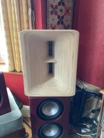
For sale is a pair of Joseph Crowes ES250 horns loaded with GRS PT6816 drivers (2 per channel). They measure flat from 250hz upto around 10k when the drivers start to drop, usable upto 13k hz. They are set up with the back open, so you get a nice cardioid response, with a nice airy sound, very cohesive as no xovers in the critical listening band. I used them for a bit just with some bass cabinets, ann enjoyable experience. They aren’t finished, just as they came off the CNC. The limitation of these horns is they must be set up vertically at the ear height as the divider in the horn introduces lobing. In one of my audio meets there was a discussion of adding a ktube into the divider for the top end. Unfortunately they have been sat gathering dust, as I build something else🙂.

It’s hard to price these as they were a prototype, and they aren’t finished, just as they came off the CNC.. Accounting for the 1 and 1/2 sheets of birch ply I used to build them, and CNC time, I think £500 the horns and drivers seems fair.
Pick up only. I am in Nottingham, England.

Attachments

  • IMG_0213.jpeg
    IMG_0213.jpeg
    353.2 KB · Views: 71
  • IMG_0214.jpeg
    IMG_0214.jpeg
    393.8 KB · Views: 75
  • IMG_0215.jpeg
    IMG_0215.jpeg
    391.7 KB · Views: 74

SketchUp 2017

Guys,
I tried freecad..... Like for 2 months...

I was able to make the panels of a cabinet
But can't join them to the actual layout

I always got...
"Too little constraints ....or too many constraints"
Suuuuuu.....,.k

Soo ...long story short
I found SketchUp 2017 on my aux external HD
That I have forgotten

Ok ... Long story short (again....gezzz)

SketchUp clicked for me!! For cab layouts

So... Google was the maker of SketchUp as free app...but Trimble bought it...when ? Can't tell , so... They removed the free version of it ...

And .....,.......,..,..
I found a 2017 copy of it on and external HD

I tried and it works on win10

Is the last freeeee version of SketchUp
V17
If you want it , let me know

Trimble removed it from the website
So if anyone want it.... It works
Today V17

Trimble don't have perpetual licenses....
They want pay as you go!!!

I hate the
"You don't own anything...but you will be happy"
Model!!!!

rear chamber on a t-line

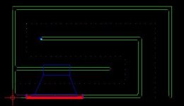
Is it possible have a chamber behind the driver in a T-line enclosure to accommodate the drivers magnet? I have a nice 12" sub but trying to keep the lines sq cm patch close to the sd of the sub while making enough room for the magnet is impossible with this sub. How important is it to keep the patch as close to sd as possible? The best I can do is double baffle the front and gain another 3/4". With just a single baffle the line needs to be 690 sq cm where the Sd is 471 sqcm. I got the drivers required space by taking the diameter of the driver times the mounting depth of the driver plus 1 inch. Am I overthinking this? Sorry if these seem like silly questions. I'm just learning horn building but am very much interested in learning all I can. Thanks. I know the drawing is far from perfect. I'm also trying to learn librecad but the scale is there as far as line width and driver depth. The dotted line was for me to measure length.

EDIT: Thank you for everybody that replied. Surprisingly I wasnt berated by a dozen people but instead got good feedback and learned something. Downside of the internet is once somethhing is out there, its out there. Bad info and all.

Attachments

  • driver issue.JPG
    driver issue.JPG
    14.4 KB · Views: 53

Digital Control of Attenuation – Repository for DIY

I’m starting this thread in the Pass Labs sub-forum, because I think there is a need for this information here, and because the idea for a digital attenuator came while building the excellent Iron Pre by Zen Mod.

There seems to be interest in a repository for free information pertaining to digital attenuation systems, in particular the Muses family of chips: 72320 and 72323.

Over the years, there have been a number of attenuators available using the Muses products. Some are commercial, but most were developed in-house by DIYers. Therefore, there is likely to exist quite a lot of knowledge in the community about implementing Muses chips.

If it weren't for generous people like Nelson Pass, Wayne Colburn, Zen Mod, Mark Johnson, XRK, 6L6, AKSA, Salas, and many others, our DIY efforts would have looked very different. And since this forum is called diyAudio, we should embrace the culture of sharing. So, in the spirit of DIY, I encourage everyone who can contribute, to share information about digital attenuation, no matter how small.

In this thread we can collaborate and share information for building our own Muses attenuators. Feel free to share your microcontroller code, libraries, schematics, tips, experiences, etc. as well as questions.

I’ll kick off by listing an Arduino library for the Muses72320 by Christoffer Hjalmarsson: github.com/qhris/Muses72320

* New - Updated library to include gain function and also other updated functions: MUSES72323 Library

Muses72320 datasheet
Muses72323 datasheet

Arduino libraries & code (generously supplied by @Nikon1975) - added 23 Sep 2023
Muses72320 Library
Muses72323 Library
Arduino code (full preamp code, including Muses72323) - added 26 Sep 2023
Arduino code for Muses72323 (Muses72323 code only. It compiles, but not tested)
Muses 72323 library for calculating the 16-bit address by @d00dz1
(Also see this thread for more information)

ESP32 code
Muses72320 on ESP

Library for Muses72323 using Soft-SPI as well as Hard-SPI by jpk73 - added 4 May 2024


MUSES72320.jpg


SSOP32 adapter board. Mouser# 854-AB-SOIC32/SSOP
SSOP32_Breakout_board_500.png

Attachments

VT130 Audio Research Repair

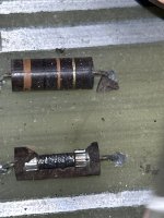
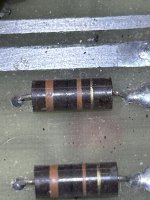
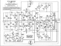
So I purchased a used Audio Research VT130 years ago. Now it blew a resistor , caused by a blown tube no doubt. What’s weird is the color code on the carbon resistors. These are 100 ohm resistors … why orange bands? Okay, I’m guessing because they can’t be brown since that is the color of the resistor? Does anyone know where I can get identical resistors for this amp?

It appears R31 blew up.

Attachments

  • IMG_3343.jpeg
    IMG_3343.jpeg
    380.7 KB · Views: 205
  • IMG_3342.jpeg
    IMG_3342.jpeg
    409.4 KB · Views: 215
  • IMG_3341.jpeg
    IMG_3341.jpeg
    143.7 KB · Views: 221

Anyone that have the Troels Gravesen The Loudspeaker 1 or 2

Anyone that have the Troels Gravesen The Loudspeaker 1 or 2 that have compared them to cornwall?

Or have a video of them playing? there is only one on youtube with poor recording.

i would like to hear the sound character of them. I dont want to put that time and money into them if they arent better then speaker that i can buy for the same amount of money.

An idea: A T-line with both ends open

Hello everyone, a while ago I had an idea that consisted of a resonant tube with 1/2 wavelength, that is, a tube with both ends open and the loudspeaker or loudspeakers would be located on the side walls.

I didn't find much content on DiyAudio about this type of resonant box, perhaps because it doesn't have many advantages compared to the well-established 1/4 wavelength resonant tube, better known as a 1/4 wavelength transmission line.

In short: anyone who has any useful content and opinion on the construction and the advantages and disadvantages of this type of resonant box is welcome.

Dual 701 automatic lift problem

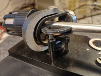
Thanks to all that helped me in this thread: Dual 701 turntable assembly problemsNow automatic seems to work with a new copper friction plate, but now I have this problem; When using arm lift, the arm raises to desired height with a little headroom/slack above, so the arm can still to move a little bit up.
When automatic raises the arm, the arm is pressed all the way to its max height, creating a lot of friction? The main lever arm (219) controlled by the cam wheel is adjusted, so it's just presses the control stud/steuer pimpel (167) up 1 mm. There seems to be a problem (adjeustment issue) between the Main lever arm (219) and the Lifting bolt (47).
Picture below shows the arm, when it's pressed all the way up by automatic.
Any ideas?

Attachments

  • 1000005601.jpg
    1000005601.jpg
    387.2 KB · Views: 74

Help with low current 12V SMPS design

Hi, Im having a go at building a low current 12v 0.4A smps. I need it to be small, and cost effective, and i hope not to have to use any ic’s.
IMG_0952.png

Here is my explanation of the circuit: 220v DC flows in via J1. This 220v is then stepped down by the resistor divider, to under 50v. This <50v powers the switching circuitry
(this low current 50v is just supplying the switching circuitry, it is NOT connected to the output). The switching circuitry switches 220vdc through isolated transformer T1.

Finally, the one and only output of this SMPS on pins 1 & 2 of t1, is completely isolated from the 220v input.

My issue is that Q5 isn't switching, i believe the astable multivibrator is drawing too much current from the 50v voltage divider. What can i do to supply the astable multivibrator.

I could increase the wattage handling of the voltage divider resistors, but to begin with this whole voltage divider method to supply the multivibrator is very inefficient.
I imagine everyone is scared off now.

Attachments

  • IMG_0951.jpeg
    IMG_0951.jpeg
    314.7 KB · Views: 46

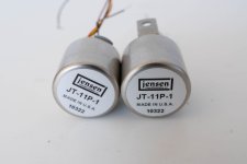
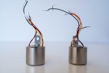
For Sale Pair of Jensen JT-11P-1

I dissasembled the amps described here for a different project:

https://www.diyaudio.com/community/threads/my-experience-building-a-drd-d3a-300b-amp.61776/

I'll be selling different parts of the amps.

Here I'm selling a pair of Jensen JT-11P-1 Input transformers.

Price is 150 euro + shipping of your choice.

Attachments

  • DSC05000 s.jpg
    DSC05000 s.jpg
    41.5 KB · Views: 55
  • DSC05003 s.jpg
    DSC05003 s.jpg
    44.5 KB · Views: 57

DIY NEAT IOTA ALPHA project. Anybody know what tweeter to use?

Hi, Im a pretty new to DIY speakers. I have just done a couple of kits before.
Now I want to make a "copy" of the Neat Iota Alpha speakers, I like the look of them and I read a lot of good reviews for such a small speaker.

I have been digging around on the net and found some info. I have the dimensions and the name of the woofer and mid drivers.
But Im struggling with the tweeters.
They use Peerless SDS-P830656 woofers and Peerless HDS-P830870 mid drivers.
The tweeter they use are listed as 50mm EMIT Planar Magnetic, but I cant find them on the internet.

These are very cheap drivers and I find it a bit strange that the price of the speakers from Neat are over 2000 $ here in Norway!

So, do anybody know where I can buy the tweeters they use, or can anybody give me some good advice when it comes to pairing the Peerless drivers with a matching (
Neat_Iota_Alpha_1.jpg
Neat_Iota_Alpha_2.jpg
Neat_Iota_Alpha_3.jpg
Neat_Iota_Alpha_4.jpg
ribbon) tweeter?
The Neat speakers are 2.5 way speakers and I will add some pixs here.
I will prob need some help if possible with the X-over, but I did read that they are crossed over at 4k and 80 hz

Hope somebody can help me out here.

B

From Telecaster upwards

Hi from Sydney!

Started my journey a few months back by buying a soldering station and fixing a buzzy Fender Telecaster. Difficulty level 1/5 but satisfaction level 5/5 🙂

Moved on to replacing a broken USB port on a microphone, and then repairing another guitar I got for $40 from eBay.

Big step up, but recently purchased an old, faulty Sony subwoofer for $6 (from eBay), which I'm using as a project to up my game in electronics in general.

Glad to meet you!
Cam.

Linear Audio High-voltage Delay for Tube Amplifiers V4

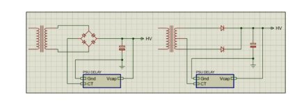
Hi, Does anyone want to take on the challenge on how to hook this up in my circuit? Much thanks in advance!

“The topology is shown in figure 1. By inserting the switch in the return line to the power transformer I leave everything after the last reservoir cap unchanged. So there is no impact on the power supply quality and no messing up any carefully laid out ground circuitry. It can be used either with a bridge-type rectifier or a center-tapped secondary with a double-phase rectifier as shown.

With a Center Tap transformer, the board is connected between Gnd and Center Tap. With a full bridge rectifier, it is connected between ground and the gnd output of the diode bridge. Easy, simple, no risk.”

Attachments

  • B7E904D0-DE18-4B89-B1F3-8F7544109690.jpeg
    B7E904D0-DE18-4B89-B1F3-8F7544109690.jpeg
    46.5 KB · Views: 124
  • 4E17A0DA-E392-4B8E-81DA-1E8B574E42E4.jpeg
    4E17A0DA-E392-4B8E-81DA-1E8B574E42E4.jpeg
    505.2 KB · Views: 121

Question about multiple ports

Hi,
A speaker demo popped up in my YT short feed.
It was a Storgaard&Vestskov FENJA 3 way. (See: https://www.sv-audio.com/fenja-3way-floorstanding-speaker/)

The speaker looks like its 3 separate cabinets (Mid/Tweeter, 2 Woofers, 2 Woofers) And on the back, the two sets of woofers have 3 ports.
(The tweeter/mid cabinet has 1 port and a rear facing tweeter)

So my newbie question... w 3 ports... how do you model it? Would they have different length tubes for different frequency tuning?
What's the logic behind it?
Just trying to do a mental exercise of reverse engineering their speaker.

Thx

Build Guide Maintenance

I just wanted to highlight an issue I run into whenever I think about doing a non-beginner DIYAudio build, and gently suggest that maybe a process could be developed to rectify the issue. I would offer to help with this, but the whole problem is that the people who could help, probably aren't aware of the problem at all, and those who are aware, don't yet know enough to assist.

Let me explain.

I've built a few kits now, from various vendors, varying in complexity but all fairly hand-holdy in nature. A Bottlehead Crack, a Whammy, a CMOY, two ACAs, a Bottlehead S.E.X, and a Sangaku. Not a lot of guesswork for any of those. Nothing more complex. This is because, while my soldering is pretty decent now, I don't have the technical know how to 'wing it' yet, nor do I have the more expensive tools to aid in doing that (no scope, no variac, etc.). There seems to be this massive gulf between simple kits that tell you how to do everything (ACA, Whammy, etc.), and the serious business involving BYO mains power supply and so forth (any of the bigger power amps, for example).

This is okay, as I figure there are guides for the individual bits that make up these projects (soft start, speaker protection, PSU, etc) - surely I can piece these together...

And this is where I run into trouble - the build guides are a bit of a mess.

Now, I understand that everyone making these guides is volunteering their time, and doing their best, and they all have lives. And I understand that the forum exists, but the roadblock I keep running into goes a bit like this:

  • I decide to build a power amp
  • I find the build guide is fairly detailed up to a point, but unfinished, or anywhere up to 10 years and 3 versions out of date, and the BoM is for a completely different version of the board
  • I go to the forum and search and wade through the relevant discussion thread that contains some useful info, but also hundreds of pages of conversation, bickering, off-topic stuff, and weird modifications that are cool but only further confuse the issue
  • I know I need to build a power supply, and that build guide is sort of up to date, but doesn't go into much detail on how to link it up with the other boards I'm building, assumes knowledge I don't possess, and it's also written for a 120vac audience and I'm in a 230vac country and can't quite suss out how to modify the instructions (and BoM) to suit
  • I go to the forum again and find a few pictures that suggest certain things, but no hard info
  • I also find that people say the soft start and speaker protection boards are important, so I look into those
  • I find that the relays for the soft start are no longer made (with no obvious replacement), that the BOM has not been updated in years, that I need an additional transformer to run the board, that maybe it's not going to work for this project anyway, and that there are many custom solutions that others are happy with, but I would have no idea how to build those myself
  • I get a vague sense of how these things link up, but again, nothing concrete
  • I look at the enormity of the things I don't know, the potential risk posed by my ignorance, and I give up
This happened to me after buying 50% of what I needed to build an F5, and I ended up selling the parts off out of frustration as the whole thing had become an albatross around my neck. Every so often I build up the courage to try again, but remember how much money I wasted the first time, and lose confidence. That's no-one's fault but my own, but...

I honestly believe that if the build guides and BoMs underwent some kind of once-a-year maintenance (check the BoM and amend as necessary, aggregate all forum addenda and add it to the guide, etc.), it would be a lot easier for eager but inexperienced people like myself to have a crack and learn something. As it is, it feels like it's just the same experienced people in the forums building out these kits, and they don't need the build guides, or can fill in the gaps unassisted, so the build guides are left untended.

Anyway, those are my thoughts. Please be kind - it's just a gentle, well-meaning nudge. 🙂

Mystery sound on switch-on. Advice required!

I have been given an amplifier, a Marantz 1060 from the late '70s It came from its original owner and is in beautiful condition with a sound to match. However, when I switch it on there is a rustling scratchy sound through my speakers (LS3/5a) for two or three seconds. This is independent of volume setting. I am reasonably happy weilding a soldering iron, but where do I start? Instinct tells me some capacitors need changing, I assume in the power supply. Am I on the right track?

Despite its age, this seems to be a highly sought after amplifier in the USA with lots of rebuild and capacitor kits for sale there, and I would like to continue using it.

Thanks for any advice.

What will happen when using 16 ohm load on a 8 ohm designed crossover

I know the basic theory that the crossover points for a first order xo will go 2x up or down depending on whether its a HPF or LPF when using 16 ohm load instead of 8.
But some context here.

I have a pre-build PA crossover 1,6kHz/8 ohm which is a third order HPF and second order LPF.
I have no idea how it will react if I
A) use two serial connected 8 ohm woofers (sum 16 ohm) on LPF side,
and B) add a 8 ohm resistor to the tweeter to attenuate it on the HPF side.

I understand I can use a L-PAD to maintain the HF ohm but my goal is actually to see if I can somehow increase the HPF XO point and maybe also investigate if the slope can be tamed in way not to have such a brutal Q around the xo point.

Unfortunately I cannot install any sim programs...

Help me with carbon fiber tonearm internal grounding

Years ago, I made 2 primitive Well Tempered style tonearms, one, using an older WT tonearm, the other I made with a carbon fiber tube. Both had a hum, the WT arm's ground wire, it seems, was broken and no longer reaching the screw behind the cartridge mount. Once I got a 3d printer, I began experimenting with carbon fiber arm tubes. I made 2 self standing arms, one 9" and the other 10.75". The arm tubes were quite narrow and I didn't know enough to add an internal ground wire, so, again, both had hums.I've tried again, first using a 10mm diameter carbon tube and a woven, flexible metal tubes for each pair of signal wires, which I twisted with 4-5 turns per inch. I soldered a wire to the 2 internal woven metal jackets and ran it out with the 4 signal wires to an external PIB box. I 3d printed numerous parts of these Well tempered clones (golf ball style), including the cartridge mount. I still got a hum. Perhaps the ground wire came lose.

I tried again, using a brass tube inside the carbon fiber arm tube. I fastened the ground wire to the arm tube, separated the signal wire pairs, twisting the pairs separately and feeding them thru different holes in the arm tube. I ran the ground out the hole with the right signal pair and connected the twisted pairs and ground to the integrated PIB box on a Well Tempered Simplex table, modified with older Well Tempered parts - bearing, spindle and platter (I bought it without arm or its support parts, spindle, platter). I added an extended base on this table to accommodate the taller WT bearing. I used another plastic printed cartridge mount. STILL a hum. As a test, I ran a wire from the exposed end of the internal brass tube to the ground post, hoping this would stop the hum, but the hum continued.

I am now preparing to replace my arm on the Simplex with the original Well Tempered stainless steel armI IF the broken outer ground wire can be fixed. A friend told me NOT to connect the ground the a headshell made of metal. What have I been doing wrong?
Here's a pic of my Neat-made Shield MO-19 idler with the 12" arm.

Attachments

  • Shield MO-19 - New Arm 01.jpeg
    Shield MO-19 - New Arm 01.jpeg
    635.6 KB · Views: 188

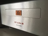
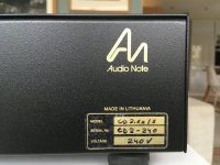
For Sale Audio Note CD 2.1x/11

MINT Audio Note CD 2.1x/11. Ali fascia. Original packaging. This is collection only from U.K. postcode HG5 as I would not trust any courier! Bank transfer only. Thanks for looking.

Attachments

  • 6F4AFC9D-DB31-4186-878F-E03986E0C097.jpeg
    6F4AFC9D-DB31-4186-878F-E03986E0C097.jpeg
    349.8 KB · Views: 203
  • 52E3470C-231E-4FA2-A1AA-F4A2D09A69B5.jpeg
    52E3470C-231E-4FA2-A1AA-F4A2D09A69B5.jpeg
    774.6 KB · Views: 178
  • 49218331-4F59-4B06-AE5C-F7E9E555A0E0.jpeg
    49218331-4F59-4B06-AE5C-F7E9E555A0E0.jpeg
    338.8 KB · Views: 163
  • 22F1F4EF-744A-4805-A072-614DD2094106.jpeg
    22F1F4EF-744A-4805-A072-614DD2094106.jpeg
    388.8 KB · Views: 167

Introductions

Hello All,

Happy to find this informative audio forum and seeing the collective knowledge exchange happening here!

My journey into vintage audio started a few years ago during the pandemic period and been acquiring (and repairing/fine tuning) various turntables, R2R's, tube consoles and other components past few years.

Prior to this phase I bought my first TT (a Sony linear tracker) in late 80's and still enjoy listening to my old vinyl. My next phase in the journey is to delve into vacuum tubes...

Looking forward to interacting more with you all.

Henry

Amplifier advice

I'm looking for a small relatively inexpensive 2.1 channel amp to power a pair of small speakers and a small sub. The speakers are rated at 50 watts and the sub 100 watts.

If there's an inexpensive stereo amp and amp for the sub that would work as well.

I'd like to keep cost under $100 if possible and it needs to be relatively simple to operate.

This is going to be for a PC at work used to show a video.

EDIT:

I found a subwoofer amp that might work.

https://www.amazon.com/Subwoofer-Amplifier-Receiver-Integrated-Audio/dp/B07942M4MC/

I'd need a stereo amp though with a variable line output.

This one has a line output, but not sure if it's controlled by the volume control.

https://www.amazon.com/Saiyin-Amplifier-Bluetooth-Integrated-Headphone/dp/B0CJ4ZY7SX

Pass Class D

About 40 years ago I was inspired to make a switching amp, and the
result was a modest 20 watt/ch unit that worked quite well.

I've been asked about this several times in the last couple weeks about
the existence of a Threshold Class D amplifier, and I was inspired to
haul it out of storage and fire it up. It still measures decently if not
to the standard that Bruno has developed, but it sounded good - I
recall that Gordon Holt liked it.

Anyway, here are some pics.

:snail:

Attachments

  • sw amp 1.JPG
    sw amp 1.JPG
    404.6 KB · Views: 847
  • sw amp 2.JPG
    sw amp 2.JPG
    498.6 KB · Views: 1,116
  • sw amp 3.JPG
    sw amp 3.JPG
    457.3 KB · Views: 786
  • sw amp 4.JPG
    sw amp 4.JPG
    456.8 KB · Views: 779
  • sw amp np.jpg
    sw amp np.jpg
    6.5 KB · Views: 832

MacBook Pro - Any Shortcomings as Design tool?

I am in need of a new laptop, and am considering the 14" MacBook Pro M3 Pro, and wondered if there were any caveats to buying one if my intention is to do some REW and other simulating and measurements? It's been a while since owning a Mac and wasn't sure if things had changed etc.

My goal is to measure some speaker projects and have a UMIK-1 from MiniDsp I would like to use.

I'm sure some software like WinISD isn't going to be possible, but wonder what else I may miss out on? Thanks and apologies if this is the wrong subforum.

I introduce myself from Andalusia

Hola a todos, estoy encantado de poder participar en este foro. Te he estado leyendo durante mucho tiempo ya que soy un entusiasta del bricolaje. Recientemente he reconstruido los paneles de unos Martin Logan Aerius y he montado un amplificador a60+, para lo cual he utilizado vuestros conocimientos que aportáis en el foro, por lo que me gustaría agradecer de antemano a aquellos que desinteresadamente comparten sus conocimientos. Saludos.

Attachments

  • WhatsApp Image 2024-09-21 at 20.09.18.jpeg
    WhatsApp Image 2024-09-21 at 20.09.18.jpeg
    83.5 KB · Views: 42
  • Like
Reactions: FrankieS

First Watt F5 and Harbeth shl5+ compatibility

I've been reading a lot about the diy F5 and so far I like what I've read. I like the philosophy behind First Watt. I'm about ready to hit check-out at the diyAudio Store but I have a few questions that I have been unable to answer through this forum/internet searches. Although its diy, it's still a significant investment to build one of these amps and I'd like to avoid a potential mismatch before I do. I plan to buy/build the F5 and the B1 based on the current version of the original plan. My system is vinyl only. I have a high quality front end: Goldring Ethos MC Cartridge and a TriChord Diablo phono preamp. My speakers are Harbeth shl5+. My amp is an old Yamaha M-40 paired with the passive Yamaha MVS-1.


Will the F5/B1 be an upgrade to my M-40/MVS-1?

Does anyone have experience pairing the First Watt F5 with the Harbeth shl5+ speakers?

How does the F5 compare with the dual mono version of ACA? Is this even a fair comparison?

Any advice will be very much appreciated, even if it means I'm better off heading in a different direction. Thank you in advance.

Raffle take 2 of R Thatcher Aleph 30 boards

I've taken the sad decision to relinquish my custody of these lovely amplifier boards. The heatsinking is just a little inconvenient for me with my equipment rack not really giving me enough air space. Being the main living room, (and being married)! I don't really have many options.

But my loss is someone's gain! And inspired by the very nature I came to have these amps and Randy's overall generosity on here, I could only do the same and give them back to the community.

So again using Randy's giveaways as inspiration I shall ask that those entering are keen to build this amplifier. If it appears in the swap meet I'm sure you will be scorned!

If interested please add you name to the list. If you could precede your name with the number in numerical order, will just help me with the random draw.

This will take place on Saturday 21st September at noon GMT.

I only ask that you cover postage.

You may see that I removed some resistors to 'detune' it to relieve some heat, but I shall reinstate these.!

Good luck!

Attachments

  • IMG20240910064511.jpg
    IMG20240910064511.jpg
    634.1 KB · Views: 153
  • IMG20240910064536.jpg
    IMG20240910064536.jpg
    513.6 KB · Views: 152

  • Locked
The Journey of DIY No-Feedback Class D Amplifier-Link

I just posted 2 threads under Class D category; the following threads will come soon.​

The Journey of DIY No-Feedback Class D Amplifier (1) Subtitle: The Motivation and Story Behind It​

https://www.diyaudio.com/community/...le-the-motivation-and-story-behind-it.417534/

The Journey of DIY No-Feedback Class D Amplifier (2): Subtitle: Why choose a Class D amplifier architecture?​

https://www.diyaudio.com/community/...oose-a-class-d-amplifier-architecture.417617/

QUAD ESL-2812X, any hope for mods?

Read about the obviously revamped Quad ESL-2812X in TAS:
"...the latest iteration has a re-designed protection circuit that allows it to be played loudly with safety. Let me tell you, walking into a room and hearing Quads, with all their usual splendid virtues, playing at nearly uncomfortably loud levels induces cognitive dissonance. But it happened, so I’m a believer."
Any chance the re-designed protection circuit would be possible to apply on earlier models?

B+5 to 18V

Hi,

I have a single 12ax7 guitar preamp. 300V for the preamp is provided by a power supply like this: https://www.aliexpress.com/item/1005006302470816.html.
I am adding boost in front of my preamp and buffer after it. Both boost and buffer use OPA134. I want to get 18V from 300V to feed both op-amps. I have attempted to do a resistor divider with 100k and 8.2k resistors. Without load I measure 20+ volts, but with the op-amps on, I get actual voltage like 3 volts on the op-amps. And the 100k resistor gets quite hot.

What is the best way to feed two OPA134 from a 300VDC supply (of course 12ax7 doesn't go anywhere, but the supply should be able to handle it all with no problems)?

Thanks.

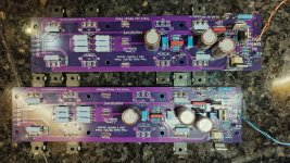
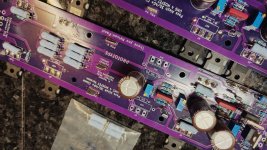
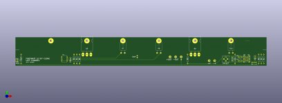
GB "long and skinny" FirstWatt J2 clone PCBs

I'm producing a set of J2 boards for myself and thought I'd do a group buy to increase volume and reduce costs a bit.

Boards are the "long and skinny" format for FirstWatt-style enclosures with a flanged heat-sink. (Boards are 14" long with 2" hole spacing.) LTP layout is for dual SJ109s (although quad SJ74s will go in the same holes).

Boardhouse will be EuroCircuits. 35uM copper (~60uM after plating). Cost will be between €15 and €25 per channel (depending on volume) + shipping. Cost includes EU VAT.

780489d1568105825-gb-skinny-firstwatt-j2-clone-pcbs-j2-board-front-jpg


780490d1568105825-gb-skinny-firstwatt-j2-clone-pcbs-j2-board-jpg


Schematic, BOM, etc. in post #15 (GB "long and skinny" FirstWatt J2 clone PCBs).

Attachments

  • J2-board-front.jpg
    J2-board-front.jpg
    196.5 KB · Views: 7,902
  • J2-board-back.jpg
    J2-board-back.jpg
    162 KB · Views: 7,797

Clarity 6.2 speakers

Has anyone actually seen or heard these? I know they're new.

I just can't believe they are being sold retail at 4000€ a pair.

If I substitute Beyma TPL150H (ie in horn) tweeters for whatever they are using then I could buy the drivers and PRs for about £870 for the Beymas and about 1400€ for the Purifis, so that's about 2400€ for drivers before crossovers and cabinets and labour.

Seriously? Time to throw in the towel on that design?

My OP-AMP rolling adventures

Amplifier build is here:

https://www.diyaudio.com/community/threads/finished-my-class-d-build-sounds-amazing.401362/

-----------------------

Very happy with the sound of the amp, but I wanted to see if a positive impact could be made with OP-AMP changes.

Supplied with the zero zone TPA3255 boards I used are the JRC 5532DD OP-AMPS. Despite being nothing special they are a great match for the amplifier boards. Detail and separation are fantastic, I was quite happy with them.
IMG20231108134259.jpg


After posting here and doing a bit of reading I decided to try the Texas Instruments OPA1656. Quite well regarded and made by TI who also make the 3255 chip contained in the amp boards. I was expecting good things.
IMG20231108134139.jpg

IMG20231108134306.jpg


First kick in the teeth was the eBay seller, or rather the packaging. Just a thin plastic sandwich bag. Inevitably one of the pair arrived with half its legs smashed off! The seller refused to replace, only refund. So I bought a replacement from another seller. Same awful packaging, this time bent legs which I carefully straightened.

They lasted 20 minutes in my system before the JRC's went back in. They sounded like pressing a loudness button with low and high end frequencies being boosted leaving the midrange (and thus a lot of detail) muffled and drowning. Soundstage was ruined, with the system now sounding like I had draped a duvet Infront of the speaker's .

Next up Burson Audio 'Vivid'
IMG20231105100128.jpg


The first nice thing is the packaging. Nice and safe, no bent of missing legs. Off to a good start over the 1656!

IMG20231108133705.jpg

These are quite large both in footprint and height. Not a problem on my boards but it could be for some.

Initial thoughts, bass was the first thing I noticed. I run my system with a pair of wharfedale Diamond 9.1's, which are fantastic speakers in my opinion, but somewhat lacking in the bass department. That said I usually listen at low volumes and I have spent many hours enjoying my system how it was.

I wasn't sure on the increase in bass that the Burson Vivids created at first. But continued testing. All of the detail and separation this system did so well was still present with an unexpected added bonus once in a blue moon.... the odd twang of a guitar at the end of a riff during Fleetwood Macs Rumours (SACD) would really pop and travel. Almost like in a surround system. The FOO FIGHTERS greatest hits provided no real changes over the JRC's apart from the previously mentioned increase in bass which after briefly swapping back to the JRC's and playing the same song again, I must say was now proving to be an improvement.

Now a volume increase to medium levels and some Bonobo - Fragments (24bit). A very atmospheric album with lots of little details like triangle twangs and sparkles. The Bursons did well here. Thankfully they left the soundstage alone just adding a touch of bass and the odd sparkle. I found myself waiting for these sparkly almost surround sound like moments. Nice.

After a couple of hours the increased bass was now a feature that I enjoy and having swapped back and to the JRC's a few times now, I need in my life.

For anyone who hasn't swapped around OP-AMPS before, we are not talking huge changes here. If I had to put a figure on it, somewhere between 5 & 10% (certainly with the opamps I used) subtle but notible.

In short I rate the Bursons, they will be staying in.

Thinking of trying OPA445 singles, in place of either LM4562 / NE5532 duals but unsure specs line up, any help much appreciated :-)

Hi
I am thinking of trying opa445's in place of either lm4562's that are in my pre/dac or swapping out some NE5532's that are in my crossover, just to see if and how they may affect the music... however, in checking out the specs of each, I am a little unsure that they align well enough not to cause any issues.

Yes you have guessed, I am a beginner with electronics, if it is broken or I don't mind if it won't work again, have a go at soldering or fixing it, so far okay with minor issues, but my pre/dac and crossover are valuable to me and I do not want to break them! , so thought I had better ask advice! Yes the dip8 sockets in both, allow the original op amp just to be pulled out and the new pushed in 🙂


NE5532 (crossover)OPA445BM (to try)LM4562 (pre amp/dac)
slew V/uS91520
gain bandwidth MHz10255
Current IP balance10pA10nA
V IP offset500uV1mV100uV
current supply8mA (2ch)4.2mA (single)10uA (2ch)
Current OP38mA / ch15mA26mA / ch
V supply min 6205
V supply max409034

I am thinking I shall need some of these:
https://www.cimarrontechnology.com/...alled&attribute_pa_bdog_1=4f-nocomponentadded

I can see the bandwidth is somewhat lower on the 445, but am unsure how this will change things...

I am not sure what the current balance is tbh, I know it only looks like a tiny number but the 445 is 1000 x different to the 4562

Once again I am not sure how the V offset will affect things in the cct, or the sound coming out the speakers

As far as I can see if I am using two 445's the current supply with be okay... not too far off

The Current OP bothers me most, as this is less than half, of the op amps already in place...

Many years ago I attempted to swap out the 4562 for a Burson op amp, the supply V was 22V if I remember correctly and the Burson tech support said that their op amps would be okay at 22V but they were not!! I have not yet measured the supply to the 5532! to check the min 20V of the 445 is met.

Any comments much appreciated, I have had a read, to try and understand what the specs mean, but I think I need a very simple explanation, and of course to know if one number differs a little or wildly what could happen :-0

Cheers for any thoughts

DIY DAC project recommendations

Hello,

Nice to meet you all. I really new here. It took me while muster up courage to do my first post (minus the introduction post). I hope I dont offend anyone here.

I am looking to build a DAC. My goal is to build a DIY DAC that brand name DACs (Denafrips, Gustard, Holo, and so on) around the $2000 mark by spending less. I am looking at around a $1200 budget. Spending less than the budget is better but I am willing to spend more if the gains in sound quality is substantial.

My electrical knowledge is close to 0 but i can solder and desolder parts. If it is too difficult, I can hire someone locally to do it as the labour cost is relatively cheap here (Thailand).

Ive seen a couple of diy projects around here such as Iancanada's, DDDACs, Gabster TD1 and Protodacs but Im not sure which one to pick. I lean more towards projects that have a youtube video as it is easier to follow the guide but I dont mind doing some more research as long as it sounds better.

My source is IOS (Iphone/Ipad) apple music lossless fed VIA USB to a DAC > Cayin Ha-3a Tube Amp > Headphones.

I hope you guys can help recommend some projects.

Thank you.

For Sale Hashimoto HW-60-5 pair (EU)

I am selling one pair of Hashimoto HW-60-5 Push Pull Output transformers.

Excellent condition, in original packaging.

Asking 630€ PayPal F&F, The transformers are in Denmark, will ship worldwide.


“The Hashimoto HW-60-5 is for applications that require the 5K Ohms primary with up to 60 Watts output level into 4, 8, 16 Ohms. The HW-60-5 is equipped with an Ultra-Linear tap, and its frequency response covers between 10Hz and 70,000Hz (+-3db). The HW-60-5 is suitable for high-powered Push-Pull applications that utilize popular vacuum tubes, such as 300B, KT-88, 6550, EL34 (6CA7), and 6L6-GC.

The HW-60-5 measures 100 (W) x 110 (D) x 120 (H) mm, and weighs 4.1Kg (9.0 LB). The Primary Inductance is 200H and the Maximum DC Current can be up to 125mA x 2. The HW-60-5 utilizes a twin Cut-Core, and the core material is 0.27mm Orient Core Hi-B which is the enhanced directional silicon steel, from Nippon Steel Corporation.”

Attachments

  • CEA2FC0D-A04B-4199-8DC7-820AEB9A156A.jpeg
    CEA2FC0D-A04B-4199-8DC7-820AEB9A156A.jpeg
    122.7 KB · Views: 133
  • 08861029-4808-4408-9925-17162E714AC4.jpeg
    08861029-4808-4408-9925-17162E714AC4.jpeg
    109.5 KB · Views: 136
  • B17CACDD-8C1F-4B47-A726-7C64A6259ADC.jpeg
    B17CACDD-8C1F-4B47-A726-7C64A6259ADC.jpeg
    102.7 KB · Views: 109
  • 3BB15CAC-59C5-489B-ADBB-FA33E56338E9.jpeg
    3BB15CAC-59C5-489B-ADBB-FA33E56338E9.jpeg
    99.2 KB · Views: 128

Powerline WiFi caused audio disturbance

I plugged a powerline wifi adapter in the mains socket close to my tube preamplifier. Now there is ticking sound. The peamplifier is an IEC Class I device, the chassis is connected to the mains protective earth. The signal ground is connected to the chassis with hum blocking antiparallel diodes (35 Ampere Graetz). The mains input of the preamplifier has "some" AC noise filter.
If I place the powerline adapter in a different socket several meters apart (perhaps on a different phase? I have a 3-phase installation in the house) the noise disappears.
Is there any way to block this noise? It seems data is being propagated on the mains wiring and it is disturbing the audio cicuitry. I am looking for a more effective filtering.

Distortion at Line outputs

I have recently purchased a second hand PS Audio ultralink Dac. Since I am using powered speakers, I do not have a preamplifier at the moment. So I tried connecting the XLR outputs of the Dac to the powered speakers and varying the input level on the back of the powered speakers for checking. I can hear a kind of distortion from the tweeters (like the tweeters have been torn and distorted ). When I connect the speakers to another system, they play perfectly fine

Since it's exactly the same in both channels, is it a problem in the power supply of the Dac or something like a DC offset at the XLR outputs of the Dac? And if it's the DC offset, how do I measure it? Also, are the speakers at a risk due to this?

Thank you

Lab Power Supply Not Getting Up To Voltage

My power supply has not been able to go up to 20v since I got it, I had gotten it to go up to 14v but it does not want to go higher than that.
Recently it has decided it won’t go above 10v (second photo, voltage knob is turned to max)
Any ideas on how to fix it? Should I recap it?

Attachments

  • IMG_0786.jpeg
    IMG_0786.jpeg
    329.2 KB · Views: 79
  • IMG_0787.jpeg
    IMG_0787.jpeg
    302.9 KB · Views: 81

Bull or what?

Copied from an online ad for what I thought was one of the worlds most respectable amplifier manufactures

unique three-point support foot "Stress-less Foot" is employed to enable stable installation without being affected by even the slightest distortion of the floor surface. Unlike conventional foot, the Stress-less foot is designed not to fix to the chassis directly, allowing it to vibrate freely to achieve a more natural sound.
The foot, made of machined steel, is not firmly fixed, but is mounted hanging from the bottom, enabling a more natural and rich sound with a sense of sound source deployment similar to that of a conventional pinpoint spike foot.

Yes they are talking about the amplifier not speakers

Opinions???🙂

How critical is achieving perfect RIAA equalization?

Hoping I'm not opening a Pandora's box but here goes 😛

I'm still in the process of designing my Rega Elicit phono clone and been wondering about this. In one of my books by a reputable author, he describes how to achieve perfect network component values for the resistors and capacitors by paralleling each component with a triming one, with the requirement that the ratio of the main and trim values be greater than the ratio of their tolerances. Of course the value measurements have to be made with a precision bridge. This is particularly helpful if one has come up with "awkward" values outside of the standard series, which is not my case.

I don't have a bridge and honestly I think it might be overkill to do this. Reason is, one of the components of the network is the output impedance of the gain stage which I believe will have worse tolerance than the 0.1% resistors and 1% capacitors the author suggests unless output transistors and their associated circuit components are also selected to be within these tolerances. And I seriously doubt manufacturers go to these lengths.

But out of curiosity I simulated my design with 1% variation factors for the passive components of both passive and active eq filters; see frequency response output plot below for 27 seven different combinations. Yes the frequency response is less flat but the maximum deviation from the theorical values is on the order of 0.3dB peak-peak for the extremes. Can this difference really be heard?

Capture d’écran 2023-12-21 135722.png


Just wondering if I need to go to the trouble of adding space for extra trim components on my PCB. I might do it for resistors as this is not that complicated but for the polystyrene caps I'm not sure as there are large variations in footprints of the parts I can get my hands on off ebay.

Thanks in advance for any insights.
-Joris
  • Like
Reactions: Drbulj

The Journey of DIY No-Feedback Class D Amplifier (3). Subtitle: Simulation Results and Reflections on the Circuit Design

After finalizing the overall design, simulations are used to select specific components and determine resistor and capacitor values, followed by circuit board manufacturing for validation and iteration to achieve the initial design goals.

The Σ-Δ (Sigma-Delta) modulation method was chosen for the following reasons:

1,A fixed-frequency PWM modulator has almost zero Power Supply Rejection Ratio(PSRR) in its output stage, meaning it has no ability to suppress power noise. This creates significant challenges for power supply design, as any noise from the power supply directly converts into audio noise and reaches the headphones. In contrast, the Σ-Δ modulator offers some level of power supply noise rejection, greatly reducing the burden on power supply design.

2,Fixed-frequency PWM modulators use a standard triangular wave (blue waveform in Figure 1(a)), which contains a lot of high-frequency components. However, the integrator-generated waveforms from multi-stage integrators (green waveform in Figure 1(a)) resemble a triangular shape but with fewer high-frequency components and faster high-frequency roll-off (as shown in Figure 1(b), with blue representing the standard triangular wave's spectrum and green representing the multi-stage integrator waveform's spectrum). In an amplifier with the same bandwidth, the multi-stage integrator waveform results in lower distortion, and the PDM modulation signal's edge jitter (rise and fall times) is smaller, leading to overall lower noise and distortion of audio signal.

1726886690177.png
1726886698329.png

(a) (b)
Figure 1, Triangle Wave, Higher-Order Integral Wave, and Their Spectrum

3,The Σ-Δ modulator can use a differential integrator circuit, which outputs a pair of equal-amplitude, opposite-polarity integrator waveforms (see Figure 2(b)) to the comparator. In contrast, the fixed-frequency PWM modulator sends a triangular wave and input signal to the comparator (Figure 2(a) shows the comparator input waveform of the fixed-frequency PWM modulator). It's clear that the slope (rate of change) at the intersection points of these two sets of input waveforms differs significantly. The differential integrator waveforms have a much steeper slope at the intersection points compared to the PWM modulator’s waveforms. This means that for the same noise level, the edge jitter of the comparator output is smaller, thus improving the overall amplifier performance. Attentive readers might have figured out that the slope at the signal crossover points of the higher-order integrator waveform should be much steeper than that of the standard triangular wave, which could be one of the reasons why the higher-order integrator performs better than the standard triangular wave.
1726886758984.png
1726886764425.png

(a) (b)
Figure 2, Comparator Input Signals of PWM and PDM Modulators

4,Compared to fixed-frequency PWM modulators, Σ-Δ modulators offer greater flexibility and room for improvement in design. For example, a Schmitt trigger mechanism can be added to the comparator in a Σ-Δ modulator to improve the stability of the PDM pulse waveform edges.

The discussion so far has focused on reducing edge jitter in the PDM pulse signal. In Class D amplifiers, the pulse signal is central to the entire system; only precise pulses can result in low noise and low THD distortion. The edges of these pulses are crucial. If edge jitter is unrelated to the input signal, it generates noise, which, while having a smaller effect on distortion, can increase the amplifier’s background noise. If edge jitter is related to the input signal—such as when the triangular wave lacks linearity—the jitter (early or late edges) will correlate with the input signal amplitude, causing nonlinear distortion and resulting in higher THD.

Through the improvements discussed above, Σ-Δ modulation can potentially achieve lower distortion. The next step is to compare performance through simulation to select different components and parameters. This is a complex and tedious process, as components interact with each other, and changes to one typically require adjustments to related parameters. I'll use a key example to explain this further.

The precision of the modulated pulse signal comes from the accuracy of the multi-order integrator signals. The amplitude and frequency of these integrator waveforms are affected by many factors, such as the zero and pole distribution in the integrator network, the depth of the Schmitt trigger in the comparator, and the oscillation control resistor. For simplicity, Figure 3 shows a basic schematic of a multi-order half-bridge Σ-Δ modulator with a Schmitt trigger. The ratio of the Schmitt trigger resistor influences the modulation frequency, and the equivalent capacitance of the high-order integrator also affects the modulation frequency. These factors further shape the integrator waveform and its amplitude.

The accuracy of the integrator waveform has already been analyzed, but its amplitude is equally important, requiring a balance between the output capability of the integrator and the performance of the comparator. In general, a larger signal fed into the comparator results in more precise outputs, but an overly large output from the integrator can cause signal distortion.

1726886850802.png

Figure 3, Multistage Half-Bridge Sigma-Delta Modulator with Schmitt Trigger Mechanism

The second important aspect is the selection of the output stage, where the industry has reached a consensus: when cost requirements are not stringent, a full-bridge configuration is typically used. The advantages of the full-bridge mode include the ability to partially cancel even-order harmonics and suppress the back current of the output filter inductor, effectively reducing the power supply fluctuations in the output stage. This is particularly beneficial for Class D amplifiers with poor power supply rejection ratio (PSRR).

The output filter is also critical, especially for Class D amplifiers using PDM modulation. Since this design uses a modulation frequency above 2 MHz, there is more flexibility in choosing the low-pass filter’s cutoff frequency. This brings significant benefits: first, a higher cutoff frequency can be chosen, so the frequency response changes with different loads won't significantly impact the amplifier’s effective bandwidth. Second, since smaller inductors are used, they provide better linearity at the same size, reducing the distortion impact on the amplifier. During simulation, it was also observed that a multi-order output filter could reduce in-band noise, although there is no theoretical explanation for this yet. I welcome any interested parties to discuss this further.

The power supply solution is equally important. This design uses a single 3000mAh lithium battery, so a step-up boost converter is required. A major issue is that the amplifier operates at over 2 MHz, which is much higher than the frequency of commonly available boost converters. During a single PWM cycle, the supply voltage may drop due to the amplifier’s high current draw, which even the best boost chips struggle to handle in such cases.

After multiple experiments, both the pre-amp and output stages ended up using a two-stage single power supply solution. The pre-amp power (for the integrator and comparator) uses a combination of a boost circuit and a Class A power supply. The Class A supply uses a high-precision reference regulator with voltage accuracy of 0.1% and power supply noise as low as a few microvolts. Additionally, the midpoint reference voltage uses the same precision reference chip, not only improving voltage accuracy but also ensuring the integrator circuit operates symmetrically, optimizing open-loop performance.

Originally, I planned to use the same design for the output stage power supply, but due to the need to drive headphones with varying impedance and sensitivity, the Class A power supply’s efficiency was too low, which affected battery life. In the end, I chose a step-up circuit combined with a high-precision, high-current LDO and large capacitors for the output stage.

Interestingly, switching from a Class A supply to an LDO + large capacitors for the output stage resulted in virtually no subjective change in sound quality. However, changing the pre-amp from an LDO to a Class A power supply led to a significant improvement in sound. The high frequencies became more transparent, the low frequencies were stronger and more extended, and the soundstage was more stable. This change was quite noticeable, without the need for careful listening. Could this be due to the higher precision in both supply and bias voltages? I would love to hear thoughts from those interested in discussing this. The first version of the pre-amp, which was discarded, used a voltage divider for the bias reference, as shown in Figure 4, with resistor accuracy of 0.1%.

1726886887267.png

Figure 4, Circuit for Generating the Bias Voltage in the Integrator

There are many other crucial details in the amplifier design and debugging process that cannot be overlooked, and I will discuss them further in appropriate contexts.

Figure 5 shows the Spice simulation results for the background noise. Within an effective bandwidth of 35 kHz, the highest background noise is as low as -170 dBV, with the low-frequency section reaching nearly -180 dBV.
1726886918175.png

Figure 5,Zero Input Circuit Configuration (Background Noise) Simulation Results

Figure 6 shows the simulation results with a 1kHz input signal. No harmonic distortion related to the 1kHz frequency was observed. However, compared to the zero-input results in Figure 5, the background noise increased by about 10dB, reaching approximately -170dBV. This frequency-independent distortion is a typical occurrence in such circuits.
1726886943532.png

Figure 6, Single Sine Wave Input Circuit Configuration Simulation Results

Figure 7 presents the amplifier simulation results based on the previous discussions. The modulation frequency is around 2.3 MHz, with an input signal peak-to-peak value of about 196 mV and an output peak-to-peak value of around 4000 mV, resulting in an overall gain of approximately 26 dB. The input signal consists of three frequencies: 500 Hz, 5 kHz, and 20 kHz. The amplifier's background noise level is about -167 dBV, which is 3 dB higher than the -170 dBV observed in the 1 kHz sine wave test shown in Figure 6, likely due to frequency-independent distortion causing this noise floor increase.

During the simulation, it was observed that different multi-stage integrator network configurations affect the spectral characteristics of frequency-independent distortion. By adjusting the integrator network, it is possible to reduce low-frequency distortion at the cost of increasing high-frequency distortion. In this design, I chose to balance the frequency-independent distortion across the spectrum, leading to a flat noise floor.

In reality, there are other approaches. One could adjust the integrator network to minimize the total or weighted power of frequency-independent noise within the effective bandwidth, without prioritizing flatness. My choice for a flat noise floor was based on the fact that amplifiers typically exhibit more distortion in high frequencies compared to low frequencies, whether it is frequency-dependent or independent. A DIY amplifier with a flat noise floor might offer a different subjective listening experience.

Given the multi-frequency input, the amplifier's total distortion is primarily composed of harmonic and intermodulation distortion. The simulation results show that the highest harmonic distortion reaches about -156 dBV, with the minimum signal-to-harmonic ratio being 152 dB. These results demonstrate excellent noise suppression and distortion control, achieving the expected high-performance standards, at least based on the simulation outcomes.

1726886970157.png

Figure 7,Multi-Sine Wave Input Circuit Configuration Simulation Results

The following lists the different distortion frequencies and their amplitudes generated from the simulation, for reference by those interested:
  • 1.5 kHz, -164.3 dBV
  • 4 kHz, -159.5 dBV
  • 9.5 kHz, -159.1 dBV
  • 10 kHz, -160.7 dBV
  • 10.5 kHz, -160.2 dBV
  • 14.5 kHz, -157 dBV
  • 15.5 kHz, -157.0 dBV
  • 19 kHz, -157.1 dBV
Overall, the simulation results show extremely low distortion, with distortion in the high-frequency range being about 5-7 dB higher than in the low-frequency range. It's noteworthy that there is a distortion point at 10 kHz, which corresponds to the second harmonic of the 5 kHz signal. However, the distortion values at these points are so low that the specific values are not very meaningful for further analysis —they are all well beyond the range of human hearing.

For those who might not be familiar with these simulation figures and find them hard to interpret, it's worth noting that if you were to input a true 24-bit audio source into the amplifier, the output would be virtually undistorted. The harmonic distortion is more than 7 dB lower than the 24-bit quantization noise, making it effectively distortion-free.

In addition, I added negative feedback to the circuit from Figure 7 and adjusted the overall gain to 20 dB, 6 dB lower than without feedback. Observing the results in Figure 8, no frequency-dependent harmonics were observed, but the overall noise floor increased by about 1 dB compared to the no-feedback case.

This phenomenon may differ from traditional Class B amplifiers. Class D amplifiers, due to their modulation frequency, generate out-of-band noise. When negative feedback is introduced, this out-of-band noise can also be fed back to the input. While negative feedback effectively suppresses harmonic distortion caused by nonlinearity, the feedback of out-of-band noise may increase frequency-independent distortion, thus raising the overall noise floor.

Although this analysis partially explains the rise in noise floor, it has not been rigorously validated and is provided for reference only. If I gather further experimental data or validation, I will share it separately in the future.

1726886998974.png

Figure 8, Simulation Results of Multi-Sine Wave Input Circuit Scheme with Global Feedback

Additionally, when observing the operating frequency of the amplifier, it becomes apparent that as the peak value of the input signal increases, the divergence of the main frequency enhances, while the peak itself becomes lower. This phenomenon is a characteristic of the sigma-delta self-oscillation architecture, providing significant advantages in electromagnetic compatibility (EMC). Since the self-oscillation frequency is not fixed, it dynamically changes under different load and signal conditions, dispersing EMI (electromagnetic interference) energy rather than concentrating it at a specific frequency. This reduces interference with other devices, making sigma-delta amplifiers relatively superior in EMC performance in practical applications.

The following text is excerpted from "Audio Power AMP Design Handbook 4th edition" by Douglas Self, which discusses the increasing distortion characteristics of traditional Class B amplifiers at higher frequencies. Although this book was published in 2006, and advancements in technology may have significantly improved the high-frequency distortion characteristics of current amplifiers, this fundamental principle still holds unless there are breakthrough developments.

1726887030906.png


From the simulation results, Class D amplifiers also adhere to this pattern, but their high-frequency distortion is only a few dB higher than the low-frequency distortion. Given the overall low distortion rates, this difference can generally be ignored.

Another noteworthy aspect is that the amplifier's phase response tends to be linear. As we know, the human ear is not very sensitive to phase response in sound. Therefore, it raises an interesting question: do linear-phase amplifiers produce different subjective listening experiences? If anyone has personal experiences or insights on this, it would be great to share and discuss!

Based on a simple calculation of the simulated distortion effects, the amplifier's THD value can reach approximately 0.0000025% with the minimal SNR is 152dB. Considering that the harmonic components are several dB above the noise floor, the THD+N value should be in the same range. This simulation result seems almost unrealistically good, so I conducted multiple verification simulations and cross-checked with actual test results, ultimately confirming that the simulation results have a certain degree of credibility. The verification approach was as follows:

  1. Device SPICE Model Verification: Each device's SPICE model was individually verified by building its recommended test circuit using the model and comparing the results with those provided by the manufacturer. The simulation results matched the manufacturer's data closely, confirming the accuracy of the models used.
  2. Comparison of Simulation and Measured Parameters: Key parameters of the fabricated circuit (such as the amplitude and shape of the integral waveform, the amplifier's oscillation frequency, and gain) were measured and compared with simulation results, with discrepancies generally kept within 10%. This directly demonstrates the reliability of the simulated circuit.
However, due to the lack of sufficiently high-precision instruments, I was unable to directly verify the noise floor and THD distortion values through measurement. This limitation makes the validation of these performance metrics in the simulation somewhat lacking, but overall, the verification results still hold reference value.

Of course, the performance results from the simulation represent only a theoretical upper limit; the actual amplifier's performance may degrade to varying degrees due to various factors. A good simulation result is merely a starting point, and the process of building the amplifier is essentially a struggle against these degradation factors.

Writing the threads has been particularly challenging for me. I’ve tried to clearly describe the simulation conditions at the time, but the reality is far more complex than what I've expressed here. If there are any unclear or incorrect points, I welcome further discussion. For now, I will share the results of my two major version of DIY AMP and some subjective listening experiences, so stay tuned!
  • Like
Reactions: rongon and kevinkr

Newb - Grand Piano bass….how do I get there?

I’m new to DIY speakers but have a good understanding of basic electronics and I’d say I’m an advanced DIY’r with all the necessary tools and equipment to build a very nice system. I just don’t know how to design the speakers for the sound I’m looking for. I’ll try to explain.

At the beginning of Sarah McLachlan’s “Angel”, on one of the best systems I’ve heard (the one I’d like to build) the grand piano gives a massive “heart thumping” feeling. The remake of Sound of Silence by Disturbed is another song that my system can’t seem to “dig” into enough.

I have Kef R300s and two large subs (SVS PB-13 Ultra and Definitive Tech Supercube Reference 111lbs ). These are run with a Denon AVR-X3800H in my home theatre/music room. I also have a KEF R200C with R800DS surrounds some DT surrounds all running in 7.2.4 for now. The room has also been treated with 6 very large hanging panels and a large floor rug.

But no matter what I do I can’t seem to tune my system to give me that intense grand piano bass. Thomas and Stereo (the YouTuber) describes his Earthquake Sound Tigris here as doing exactly that.

How would I go about building and designing a set of towers to give me this “sound” that would make it different than any other pair? Here’s where I have zero experience but it seems this frequency I’m looking for is around 300-400hz?

Is it the cabinets? Woofer size? Crossover?

I understand no one is going to be able to answer this with a single simple response, I get that it’s a combination of the parts. Maybe that’s what I’m asking, what combination of parts is more likely to give me this finished product that can give results? What general direction should I be looking? Or is it even a realistic expectation?

Thanks all in advance!
Projects by fanatics, for fanatics
Get answers and advice for everyone wanting to learn the art of audio.
Join the Community
507,492
Members
7,874,431
Messages

Filter

Forum Statistics

Threads
405,585
Messages
7,874,431
Members
507,492
Latest member
Arthur Lin