Cone loaded Smith horn

Hey all,

I have been a diy speaker builder for the last 10 years and have built a number of successful projects over the journey.

Recently I started to get into horns. I built my dad a ecconowave type speaker a few years back and more and more as time has gone on I seem to love how they sound. I have a very large shed/man cave and so horns make a lot of sense for my next speakers.

This project started as I had a bunch of material left over from various woodworking and renovation works.

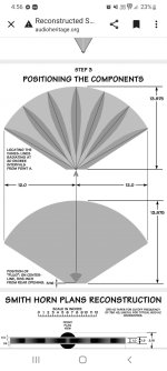
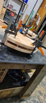
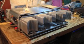
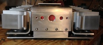
Basically a year or so ago I built some smith horns with left over 26mm laminated beech that I had from making bathroom vanities. Taken from plans on another forum and Adjusted to 5 cell and 90* horizontal pattern. I'm aware that diffraction horns have a mixed reception but they look cool af so that's where I started.

I have recently picked up some new in box faital pro 3fe22 8ohm drivers of Facebook marketplace for a very good price decided to give it a go in the smiths as I have some time at the moment to play with things- self employed, wife and 2 young kids......

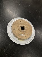
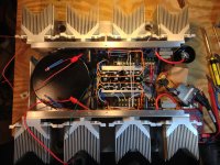
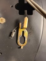
Started with a very rudimentary 2 litre airtight bucket filled with polystuff as the back chamber (obviously this is too big but just playing as a test of concept). Made a 15mm ply and 3mm mdf ring with a 25mm square hole for the entry to the horn- see attached (this is before file work to make it all neat and even so it looks pretty basic in the pic).

More to follow

Attachments

  • Screenshot_20220612-165649_Chrome.jpg
    Screenshot_20220612-165649_Chrome.jpg
    160 KB · Views: 134
  • 20220618_202656.jpg
    20220618_202656.jpg
    318.4 KB · Views: 122
  • 20220618_202706.jpg
    20220618_202706.jpg
    295.8 KB · Views: 111
  • 17265687492668307767501598999199.jpg
    17265687492668307767501598999199.jpg
    421.2 KB · Views: 120
  • Like
Reactions: EarlK and AllenB

DIY ultrasonic vinyl cleaner

Login to view embedded media
c09674925a0c668631440eadeecd71e.jpg
15d41de039191c68e3c3e44b4bc2aee.jpg

After a previous modification, this very stable ultrasonic rotary vinyl record cleaning machine is now completed.
I used a geared motor as its rotational power.
Ultrasonic cleaning can deep clean the record very clean, but it will not damage the vinyl record.
The machine can be set to a timer and can clean a set of records in about 20 minutes.

Center channel driver selection

Looking to make a center speaker to try out with movies. I have a few drivers available, some I'd rather use more than others. I'd love to utilize the tectonic tebm46 that I've had for years. I feel it's wide dispersion will be of value here.

I would like to use a wmtw configuration and was wondering what sensitivity would be ok for the woofers to work with the tebm46. My math is probably off but if I recall you gain about 3db from adding a second woofer? The tebm46 is 86db. Assuming baffle step loss of 6db, I should be safe with woofers around 88db and under. Please correct me if I'm wrong.

Hello HeadPhoneAmp Enthusiasts

Hi, the other day sorting stuff on my old bookshelf I found my old Tietze&Schenk book, and it suddenly came to me that I want to rekindle my DIY life from like 40 years before...
I wanted to start small, so I started to look at headphone amplifiers, and after a couple days of research I was hooked... I found myself fascinated by the most simple circuits with one or two active components, in their wide varieties, and I want to build them all, and hear, compare their sounds with my own ears...
I have a gazillion questions, and I registered here to have an option to ask experts if (when) I cannot find answers through my own research.
Thank you!

Rogers LS3/5a

I've been wanting a pair for a long time and have been looking at review's, one review, said, as they are not ported, where has the bass gone, etc. Has any body ported a pair of these as they are not cheap if any thing went wrong, if a hole was cut out with a hole saw, It could be glued back if it didn't work, but has anybody tried this. Paul

Vintage DAC MP1936 production

I think some friends have seen the previous post because he was very confused. I think I will reorganize and send it to him. This is a very old DAC, with a price of $200 per unit back then. Because it is the first generation chip for recording magnetic tapes. So he is very valuable. He works great and can recall warm vintage sounds. You can purchase PCB boards and ship them from China. If you are a friend of the European Union. Please provide the IOSS number, which consists of IM and 10 digits. The mailing time is about 10 days. All PCBs consist of four parts: audio input board, format conversion board, DAC decoding board, and power board. You can play app content through a Bluetooth chip (purchased in China, manufactured in Shenzhen), or use CS8412 coaxial to play CD content. COMBO384 can also be used to connect to a computer for playback, and there is also an external input IIS interface for connecting to Philips turntable playback. I will provide Taobao product connections. You can use Taobao's overseas warehouse to purchase. If you need assembly instructions and BOM list, please send an email application: 410746700@qq.com
IMG_3719.JPG
IMG_3720.JPG
IMG_3721.JPG
IMG_3722.JPG
IMG_3723.JPG
IMG_3778.JPG
平衡流程图英文.png

Say hello

I am a retired old man,was worked in electronic and ic assembly company.
Audio amplifier diy is my hobby,l often assembly audio kits for tasting different characteristics.
Amp is a complicated unit with no standard rules fit all problems,especially when assembling and wiring.l always search website for problem solving when encounted.
I join diyaudio is expect to get people's guidance and exerience to possibly improve problem and enjoy music.

Production of DAC1136/DA73/DA726 Original DAC Modules

I am very honored to have purchased 2 DAC726 chips, which are identical to DAC1136 and DAC73. These are chips from a long time ago. A chip used to record cassette tapes for opening machines. Today I designed a DAC audio decoder that works with this chip. He works great and can recall warm vintage sounds. You can purchase PCB boards and ship them from China. If you are a friend of the European Union. Please provide the IOSS number, which consists of IM and 10 digits. The mailing time is about 10 days. All PCBs consist of four parts: audio input board, format conversion board, DAC decoding board, and power board. You can play app content through a Bluetooth chip (purchased in China, manufactured in Shenzhen), or use CS8412 coaxial to play CD content. COMBO384 can also be used to connect to a computer for playback, and there is also an external input IIS interface for connecting to Philips turntable playback. I will provide Taobao product connections. You can use Taobao's overseas warehouse to purchase. If you need assembly instructions and BOM list, please send an email application: 410746700@qq.com
IMG_5081.JPG
IMG_5082.JPG
IMG_5083.JPG
IMG_5084.JPG
IMG_5085.JPG
IMG_5086.JPG

Hello from malaysia

Hello, greetings to all DIYAUDIO members. I am here asking for some help regarding my amplifier.

I will tell a brief story about what happened.

That day I was busking using the FISHMAN LOUDBOX ARTIST and I noticed that my amp was not working as usual. then I tried to open the body amp and I didn't see anything happening.

so I went to send technician "A" to repair the amp. the technician said "the preamp IC was found to be defective" so I bought it and the model was TAS5603B and the technician installed it. And after a few days, the technician changed the item but my amplifier is still not working. I took it back and changed to another technician.

then I sent it to the other technician "B" and when he opened the preamp IC and found that the board was burnt.
The technician asked me to look for the fishman loudspeaker schematic but couldn't find it. until I found this forum to ask for help from all my friends to get the schematic.

Please help me.

Attachments

  • WhatsApp Image 2024-08-31 at 12.03.29_1a7dbc7b.jpg
    WhatsApp Image 2024-08-31 at 12.03.29_1a7dbc7b.jpg
    220.6 KB · Views: 41

Harman Kardon AVR 151 and AVR 171 SMPS buzzes for a few seconds when switched on

Hello,

I have two H/K home theater amplifiers. I bought the AVR 151 as faulty, the owner said it wouldn't turn on and the power LED was blinking. When it arrived with shipping though, it was already working perfectly fine. Probably this good operation is only temporary, it will not last long, because when switched on there is a not very loud but audible hissing sound from the switching power supply section for a few seconds, which then stops, and currently all functions of the amplifier work fine.
Is there anyone here who is familiar with SMPSs and could tell me what this buzzing sound could be? Because it doesn't seem normal and could indicate some kind of fault that will come out sooner or later in the unit.
And a friend of mine gave me an AVR 171 which behaves the very same way, the buzzing sound comes for a few seconds, goes away, but all the functions of the amp are currently working fine.
So it occurred to me that it's not a fault, but it could be that the power supplies in both amps are dying.
The SMPSs of the AVR 151 and AVR 171 is the same, except that some electrolytic capacitors in the 171 are bigger.

Istvan

Harman Kardon AVR 151 and AVR 171 SMPS buzzes for a few seconds when switched on

Hello!

I have two H/K home theater amplifiers. I bought the AVR 151 as faulty, the owner said it wouldn't turn on and the power LED was blinking. When it arrived with shipping though, it was already working perfectly fine. Probably this good operation is only temporary, it will not last long, because when switched on there is a not very loud but audible buzzing sound from the switching power supply section for a few seconds, which then stops, and currently all functions of the amplifier work fine.
Is there anyone here who is familiar with SMPSs and could tell me what this buzzing sound could be? Because it doesn't seem normal and could indicate some kind of fault that will come out sooner or later in the unit.
And a friend of mine gave me an AVR 171 which behaves the very same way, the buzzing sound comes for a few seconds, goes away, but all the functions of the amp are currently working fine.
So it occurred to me that it's not a fault, but it could be that the power supplies in both amps are dying.

Istvan

WTB [EU] diyAudio Store F4 PCBs

Winter's coming, and so are the Class A amp builds.

This time I'm looking for someone from the EU who's got a surplus pair of F4 PCBs from the diyAudio store. I know that I could order from the store, but I'll ask here first.

I could also trade for a pair of Peter Daniel's F4 PCBs that I have. It's just that the diyAudio store PCBs would be a better fit for my heatsinks.

Help with Goldmund Telos 600 clone?

Hello.
I have bought this boards supposed to be from true Goldmund amp Telos 600 but I’m pretty sure they are not Goldmund boards because they doesn’t match to telos 600 schematics.

Maybe this is a protect already discussed in this forum. I need the schematics to install the fets and some transistors that are not populated. My big concern is the N jfet that it is not 2N5565 but U402 and I don’t know if this is just something to install it or the input board is designed for U402 Jfet.

Attachments

  • IMG_2723.jpeg
    IMG_2723.jpeg
    417.4 KB · Views: 354
  • IMG_2722.jpeg
    IMG_2722.jpeg
    529 KB · Views: 329
  • Like
Reactions: meanman1964

Hiss from a Parasound Zamp v.3 with new DAC.

Im using my Parasound Zamp v.3 for my computer audio system. The chain goes to the computer, USB isolator, USB DAC, ZAMP, and Monitor Audio Silver 2 bookshelf speakers. The amp has always had a hum/hiss with no inputs, but it went away with the DAC so I never though much about it. I recently upgraded my DAC, and the new DAC goes idle after a few seconds, essentially shutting off the output, resulting in the ZAMP humming/hissing. I swapped amps with a Yamaha M-45 and the old Yamaha is silent with in the exact same setup. You can even unplug the RCAs from the back and the Yamaha stays silent.

I'm thought it might be floating inputs that the Zamp doesn't like. I checked the resistance between ground and signal, found it to be 19.5kohm (the Yamaha measured 20.4kohm) so that doesn't seem to be an issue. The ground checks out (and the Yamaha doesn't have issues), so I don't believe it is a ground loop issue (I even ran a separate ground to the chassis of the amp and tried a cheater plug). The Zamp also has the option to lift the ground, and that has no effect. I opened it up Zamp and didn't see any obvious issues with the caps.

The Yamaha is a tank, and I don't have room at my desk for it. How do I get the Zamp to be quiet? I tried an app called Sound Keeper, which keeps the DAC from sleeping, it works but that seems like a Band-Aid solution and doesn't fix the real issue. Is this just normal for a Zamp? Does it need a recap job (or just bad design)? Is it time to upgrade to one of the new TPA3255 chip amps?

Thanks!

Linkwitz Orion-type speaker w/o woofer?

I recently heard the Linkwitz LX521 and was quite impressed to say the least. As a DIY project this would be a bit too much, though, and a bit too pricey - but which got me thinking.
Linkwitz also designed the Orion, and I was wondering, if someone has done a project/plan/kit to build just the midrange/tweeter part of the Orion leaving out the woofer part, and just filling in the lower end with e.g. a Rythmik sub?

LS3/5a fan

Hi,

I've been an LS3/5a user since my first job, which was at BBC Research Dept in Kingswood Warren, although I was in the service planning dept. But I was able to use my staff discount to be buy my first pair.

Used them ever since, although I added the AB-1 when it came out, then later the AB-2 from Stirling, along with upgrading to Stirling thin-wall cabinets and Cicable external crossovers and then Stirling V2s with Xtracable external crossovers. Always with Quad power amps (306->707->909 monos->QMPs), and lately Music First Audio pre-amps.

So earlier in the year I visited Stirling Broadcast to get some help replacing a blown T27, but saw that Doug was suffering health issues and also saw that he had accumulated a lot of stock that he had built up in the covid era. His friend and neighbour, who was helping look after him, pointed this out and also questioned what could be done with it. As I like a challenge I said I would help and try to get it all sold. That was back in May 2024 and I am still working on it!

So the reason for joining was that I have always wanted a better quality crossover in the AB-2s, feeling uneasy that the crossover in the V3 LS3/5as is of a very hgh quallity (nearly as good as my external crossovers) but when using the AB-2 as it was designed, this crossover is being fed a band-passed signal from the mediocre crossover in the AB-2. When using my external crossovers the situation isn't quite as bad as the HF of the LS3/5a comes straight from the external crossover and doesn't touch the AB-2.

Now I am a software engineer that is trying to retire early so loudspeaker design is not my forte. When I worked at the BBC I did start to get into it and built a box to test the resonant frequency of a Nakamichi speaker I was putting in my car so I could build an enclosure for it, but never got around to completing that project.

Although I have tried to persuade Derek Hughes to design me a better AB-2 crossover (and AB-1 before that) he doesn't seem very enthusiastic (perhaps unsurprisingly), but he has pointed me to a suitable air-cored inductor to use, and also made some comments about replacing the two capacitors (one elctrolytic and a smaller PP which must be a bypass -according to what I read only a few days ago!).

I've been reading a bit online and also just bought some courses on udemy (!) but one of his specifications, that the replacement PP capacitor (the electrolytic is going) has to have a voltage rating of between 50V and 150V is causing me problems. So my first technical question after this introduction is probably going to be about that !!

Andrew

FLH design questions - multiple vs single drivers, etc

Getting started on a midbass horn for use with my A290s. I have some thoughts on the midbass enclosure design I'd like to clear up with some of you horn experts. Hornresp would probably answer this for me, but at the moment, the software wont open properly for me without errors.

While calculating the WG profile, I was curious (hoping) if the throat surface area appropriate for a single LF driver could be simply assumed to double when adding a second identical driver? Does this also potentially shorten the total WG length?

In my case, 2 x B&C 12MH32s per side were planned for use in a FLH design similar to Inlow spec FL midbass horn. I was initially going to use a single 12PE32 per side, but started thinking about trying the altec A7 expo-reflex design instead. This brings me to the next potential issue, given the lack of rear chamber on the A7 screwing up the WGs performance. In the past, I've only built FLHs with reactance annuling rear chambers, not with the reflex rear enclosure setup of the A7. I'd imagine the transient response of a well designed traditional FLH would go south with the expo-reflex design, as most RLHs with 1/4 wave TLs would have similar issues not having any reactance annuling.

The 12MH32 requires a smaller throat entry surface area than the 12PE32, so my theory of doubling the total throat entry surface of a dual LF driver horn would allow for a shorter horn length, assuming this would be like starting the WG profile at a larger throat surface area entry point and ending at the same 1/2 - 1/4 pi mouth area? Is my theory correct on this, or am I just being misled by my morning dose of meds?

For Sale 3 SENCORE 39G292 Low Capacitance 10X Oscilloscope Probes

SOLD - THANK YOU.

Three excellent condition Sencore 39G292 150mHz low capacitance probes (photo shows 2). Note: some sources cite this as 100mHz, others state 150mHz. These are the mates to the SC3100 Sencore 'scopes, so they have both a ground clip lead and the DMM lead for that 'scope model. Two of these have the DMM lead, the third does not, so it is discounted (buy all three for the best price).

I've tested these with my Tektronix 2236A, 2465B, and Rigol DS2072A and they work great. They are a bit bulkier than Tek probes, but if you have an SC3100 and want the correct probes, or want a good set of 150(100)mHz probes for a good price, check these out.

THESE ARE NOW SOLD - THANK YOU.

Sorry, no shipping outside CONUS.

Thank you.

1:10 rule impedance matching

Hi,
In order to match impedances of tube source, attenuator and tube power amplifier to 1:10 rule I just need explenation how source "sees" input impedance. Which of this two calculations are correct:
1. Z_pot = 10 x Z_out and Z_in=10 x Z_pot (difficult to achieve)
or
2. Z_pot || Z_in = 10 x Z_out (possible to achieve)

In attached diagram C1 and C2 represents capacity of interconnect cables. C1 is very short cable, C2 is around 30cm. I don't know if they can be ignored in this calculation.
Z_out = 4K5
Z_in= from 86K (20khz) to 330K (<5khz)

Attachments

  • PXL_20240920_074151865.jpg
    PXL_20240920_074151865.jpg
    202.8 KB · Views: 163

BASEFACE 1.4D Chinese Clone distortion issue

Hi,

I’m working on a clone BASSFACE class D amplifier that was brought in with a burnt-out power supply and a dead output section.

It’s using 10 IRF260Ns for its output.

After fixing the power supply, I noticed the drive waveform on the output had a step on the turn-on, and the low-side FETs were running hot without a load at idle.

I changed the driver transistors from 2316, 916 to 2073, 940 respectively, and doing so solved the problem with the drive waveform. However, the amplifier was getting distortion well before the clipping point. The driver transistors on the low side, especially the 2073, were also running hot when I did this. I switched back to the original drivers to see if the distortion was also present with them fitted, and indeed it was, and it was much worse.

I also tried leaving the 2073, 940 on the high side and the original transistors on the low side, which was somewhat better. I also tried other transistors like 649, 669, and the results were much worse.

Any idea on what is causing this and how I can fix it?

Any help would be greatly appreciated. (I’m kind of new to fixing class D amps 😅)

Also, the rail voltage is 180 peak-to-peak.
IMG_20240923_224207-01.jpeg

IMG_20240923_224420-01.jpeg

For Sale complete F6 working perfectly but for sale sold as is for parts

I am moving out of the country in 90 days so it is time to sell the last of the stuff I have been using. My Nelson Pass F6 (see pictures) has been above my soldering bench driving some very old Bang & Olufsen Red Line 60's. It's been good! All things must pass. First the cream, this F6 was not my first rodeo and I really like the construction for the chassis. I never intended to sell it so it may encounter some "settling" in shipment. THUS I offer it up as a complete set of (working) parts.

I have been though shipping hazards before, sometimes everything goes just fine, most times things go just fine. I have no time to make things right IF they go wrong, like one channel out upon arrival. Everything is great but you must consider it as PARTS.

Everything should hold together. It is serious construction! You can see I was free with the fasteners. I am also very good at packing! I am still no match for a 4 foot fall from the conveyer.

AS an offering of parts I figure it should sell quickly at $200.00 even if it takes $100 to ship it. I live way up the Michigan peninsula in Traverse City (49685) if you want to come and get it. That would be sweet.

I also have a sweet little BA front end as preamp I'll put in a second ad to keep things straight 🙂... and Wayne's 2018 preamp, Those same B&O speakers, and cables and...

Cheers!

Attachments

  • f6 open top.jpg
    f6 open top.jpg
    510.4 KB · Views: 422
  • f6 high left.jpg
    f6 high left.jpg
    346.6 KB · Views: 419
  • evening's work done.jpg
    evening's work done.jpg
    424 KB · Views: 409
  • f6 rr.jpg
    f6 rr.jpg
    309.2 KB · Views: 410
  • f6 frt.jpg
    f6 frt.jpg
    230.7 KB · Views: 408
  • Frt rr f6.jpg
    Frt rr f6.jpg
    293.3 KB · Views: 416

building boxes for speakers

I'm working on a sound installation that will use eight of those speakers that will be placed on a floor in a art gallery.

The speakers should be as low as possible. How can I planning the wooden box? is there any rules for that?

I'm using this 4mm plywood for laser cutter for building the boxes.
I care about the esthetic of the speakers (meaning speakers must be low as possible to the floor) but the sound quality is also consideration.

Any tips?

Hi from Bretagne

Hi, I'm not an electronics engineer, but I have a friend who is. As an amateur musician, I'm sometimes confronted with equipment breakdowns, and if I can repair them myself (for faults that are easy to detect) I do, otherwise I ask someone more competent. This is what led me to your forum to help my electronics engineer friend (who doesn't have much time) find the fault with an old Philips amp that I hope we'll soon wake up. 🙂

Behringer UCA202: Fixing the Low Frequency Cross-talk

I meant to post this information 10 years ago…better late than never, I guess.

The UCA202 is not state of the art by any means, but small, light, rugged, no fiddly knobs to adjust or get noisy, and cheap…works great for non-critical travel measurement system. However, as many have noticed, if you try to use it for impedance measurements using the built in headphone amp and a 47 – 100 ohm reference resistance you will notice an issue with rising impedance error at low frequencies. I traced the problem to an unregulated voltage reference that is shared by all op amps. The op amps are powered directly from the USB +5V rather than a split +/- Supply. The voltage reference is needed to position the audio signal between ground and +5V.

Attachment #1: A trend plot of measured impedance for a 5 ohm resistor for a range of reference resistor values used with a power amp to illustrate the issue.

Attachment #2: Here is an overlay plot showing the cross-talk vs the loop-back measurement.
- red curve is the loop back measurement
- orange curve is stock unit with inputs shorted
- grey and blued curves are with inputs shorted but bigger filter cap for reference voltage
- purple curve is when input op amp reference is switched to using the regulated Vref in the PCM2902

Attachment #3: One option for improvement is to increase the size of the capacitor (C13) used to filter/stabilize the reference voltage . The board has room for a 1000uF. This is a simple option that provides about 20dB improvement.

Attachment #4: A better option, if your soldering skills are up for it, is to use a separate reference voltage source for the input op amp. Rather than adding circuitry, I found from the TI datasheet that pin 14 on the PCM2902 provides a regulated reference voltage for the internal DAC/ADC buffers. Furthermore, the TI demo board schematic shows this voltage being used as reference voltage for external op amp buffers as well.
- remove R14 & R21 (required because of direct coupling in the monitor signal path, the monitor switch will no longer work)
- cut trace between pin 5 of IC5 and the thru hole (this is the shared voltage reference trace)
- add connection from pin 5 of IC5 to pin 14 of PCM2902 (conveniently available at C1)

Attachment #5: A comparison of improvements from the two different fix options with 47 ohm reference resistor.

Attachments #6,7: Excerpts from TI documentation

* * * UPDATE * * * 2024-09-23
diyAudio member kinap35 posted links to videos showing alternative fix using an LM385-2.5 voltage reference.
This method retains the functionality of the monitor switch, if that is important.
Videos links: Post #23
Cross-talk Results: Post #26

Attachments

  • UCA202_Z_Rsense_Trend.png
    UCA202_Z_Rsense_Trend.png
    46.5 KB · Views: 1,093
  • UCA202_Crosstalk_trends.png
    UCA202_Crosstalk_trends.png
    43.2 KB · Views: 1,208
  • UCA202_Fix_01.jpg
    UCA202_Fix_01.jpg
    108.1 KB · Views: 1,365
  • UCA202_Fix_02.jpg
    UCA202_Fix_02.jpg
    114.7 KB · Views: 1,571
  • UCA202_Fix_trends.png
    UCA202_Fix_trends.png
    18.3 KB · Views: 1,160
  • TI_PCM2902_Internal_Vref.png
    TI_PCM2902_Internal_Vref.png
    28.1 KB · Views: 1,152
  • TI_PCM2902_DemoBoard.png
    TI_PCM2902_DemoBoard.png
    108.4 KB · Views: 1,524

Help 3D scan a horn

Hi all,

I guess I better post a new thread…

I have a single JBL 4367 plastic horn that is 22-1/16” wide and about 10” deep. Since I have no idea how to replicate it I imagine I can 3D scan it and use the file to print a copy or a pair.

Can anyone help with advice? Can it be done with an iPhone or I need a special high resolution scanner? Thanks in advance!

Hello from France

I'm new here and looking for informations and schematics to get a Nec A-11 amplier repaired.
I bought it new in the early 80's.
It needs some service repair for a long time now but local technician is unable to find sevice manual.
A few years ago I was in Tokyo and asked for that manual directly at the NEC company building and they told me everything was destroyed !...

Going for a PAP Trio15 DIY Project

I am a skilled wood worker and I know how to solder. I have built and helped friends build diy speaker kits before with great success. Those kits came with box dimensions and crossover schematics and part lists.

I have been scouring the internet for a while now looking for an open baffle diy kit that is similar to the PAP Trio15.

I haven't really found any kits per se, but I have found many people who have successfully built their own pair. I would like to use passive crossovers for mine. Unfortunately many of the posts I have found, people are using active crossovers such as the miniDSP. I do not want to do this. One, cost. Two, I already have a dedicated amp (emotiva xpa-2). And, three it seems most reviews say they end up sounding better with a passive crossover.

It appears many people are using these speakers for their diy builds:

1x Tang Band W8-1808
https://www.parts-express.com/Tang-Band-W8-1808-8-Neodymium-Full-Range-Driver-264-894

2x Eminence Alpha-15A
https://www.parts-express.com/Eminence-Alpha-15A-15-Driver-290-407

A lot of people also talk about using the Tang Band W8-1808 from Parts Express and getting the OB-A15Neo from PAP. However, it appears PAP is no longer selling the OB-A15Neo on its own. 🙁

Are people using the Eminence Alpha-15A as a drop in replacement to the OB-A15Neo? Could it be used as a replacement without crossover modifications?

If not, is there a replacement to the OB-A15Neo that can be sourced from someone else, since PAP is no longer selling individual drivers?

A user here, @PDRCanada, had a crossover schematic in his photobucket.

https://hosting.photobucket.com/alb...s over 100MF-100uF 33MF-33uF_zpswaualkg3.jpg

But, i am not 100% sure that is the actual correct crossover? And, if it is, can it be used with the Eminence woofer?

They also posted some photos of their crossovers as well:

https://www.diyaudio.com/community/...t-open-baffle-kits.300710/page-2#post-4958928

I am not skilled enought to be able to compare the photos to the schematic and know if I am looking at the same thing.

I have posted a follow up, asking these questions, but then I realized that this community seems to like when new threads are created, so that is when I created this.

Any help in getting me started on the right direction is greatly appreciated!

Thanks!

Heater Wiring - the Good the Bad and the Ugly

looking over photos of DIY projects on the net, and hearing the many stories about hum, makes me want to offer some observations that might help amateur builders.


Understanding the problem of tube heaters and hum is the first step toward ensuring your wiring job will be good enough to give happy results (no hum).

(1) The heater supply is usually A.C. (alternating current), a 50 or 60 cycle voltage taken from a winding off of the power-supply transformer. As such, it is usually more or less a sine-curve (but often with additional components, harmonics), but can actually appear as gross as a sawtooth depending upon the quality of your line voltage.

(2) For hi-fi and musical applications, the heater lines unfortunately provide a way in for noise from the mains (random hash, transients), and also radio frequency noise (RF), because the wires can also act as antennae, picking up noise from nearby motors and other equipment.

(3) So even if you don't convert your Alternating Current (A.C.) power to Direct Current (D.C.), you will still want to have some filtering and protection from line and radio noise.

(4) Also, if you don't convert to D.C., the 60 cycle A.C. hum will leak into other nearby circuits through the electromagnetic field coming off the heater wires, unless you take some precautions.

(5) As well, noise from other parts of the amp (the High Voltage HV supply, the screen supply and bias supplies) can also pick up and inject noise back into the heater lines.

(6) Many people don't bother to convert A.C. to D.C. for the heaters, and so other methods must be applied to minimize hum and noise. This is sometimes a cheaper solution.

In any case, hum and noise remains a problem with amplifier circuits, so basic strategies should be used.

Regardless of whether or not you convert A.C. to D.C. (removing most of the hum), the Mains coming into the amp should be filtered and/or isolated from line noise. This can be done with a basic capacitor network on the lines.
It can be built into the line plug:


-----------------------------------------------------
Next, comes the layout of the heater wiring itself.

(1) The A.C. supply wires are twisted together, to collapse and minimize the field around each. At the same time as current flows in one direction on one line, it is returning in the opposite direction on the other line, and the two fields interact and cancel each other out.


(2) But there is ANOTHER reason
why the wires are twisted together, which is often forgotten or neglected: It also stiffens the delivery system and minimizes movement of the wires. What movement? Any motion in a wire carrying current, or in a magnetic field generates a signal, or creates a coupling field. The motion can be very small, almost invisible, as in a guitar or violin string. It will still be very significant here.


The practice of twisting wires is also done to greatly stiffen them, minimizing motion and coupling fields.

(3) This is also the reason why SOLID wire (such as 18 to 14 gauge) should be used for heater leads. In fact, any and all electrical activity has an impact on all metal in the area, and in case you haven't guessed it, will also cause physical forces of motion on the wires. Here we DON'T want flexibility, but rather stiffness.

If you doubt this, or think it is insignificant,
try loosening the bracing bolts on your power transformer,
and listening to the horrible vibrating rattles as the E-I sections bounce around.

(4) Getting back to the theory behind twisting the wires, We want to recognise also that the number of twists is also strongly related to the DISTANCE to the next object that might pick up the signal, by the Inverse Square Law:

Quote:
"The circuit is essentially a coreless electromagnet with only a single turn of wire. By twisting the wires, we produce many small electromagnets, instead of one large one. Furthermore, these many small magnets are pointing in alternating directions. If we were very close to one of these magnets, we could still detect it, but once we are a small distance away, the adjacent opposing magnets will cancel it out (figure 3)."


Thus we want as many twists as possible (per inch), to minimize the proximity effect to other nearby objects.

On the other hand, if you twist the wires too tight, you can also short them or break them or weaken them to the point where they generate resistance and heat unevenly, so there is a limit to how much you can coil / twist the wires before you risk damaging them.

Now we are ready to understand why many seemingly good efforts at heater-wire dressing fail.

The hum is directly related to distance:

(1) The most sensitive components are the ones closest to the heater wire. That would be the area right around the socket! This is typically where the twisting-dressing technique is done the most poorly and sloppily!

(2) Wires at a right-angle to the heater-wire are the least sensitive to hum. Often wires and components are laid out badly in regard to this obvious issue: orientation.

(3) Other components may or may not be more or less sensitive to heater hum depending on orientation.
THERE ARE NO general rules for this. For instance, its a bit tricky to orient a coil (or a cap!) for minimum hum, because it has a 3-dimensional field! Some components will be sensitive in ANY orientation, and must be shielded.

Rockford Fosgate Punch 600x4

This Rockford Fosgate Punch 600x4 I have here came in with one defect channel.
Exchanged:
2x IRF 5210 and 2x IRF3415
R229 10 ohm
R228 20 ohm
2x 0,1 Ohm (drain/source resistors)
2x 0,05 Ohm current sense (R245/R234)

When starting up, the power supply is pulsing on/off/on like 5Hz., like it's in protection. No LED is on.
Checked the board, but cannot find any burnt or defective part, all output mosfets are ok.
I think there must be something wrong in the defective channel.

Without the rectifiers MUR1620's the power supply works normal, LM337/317 low power supply is ok.

Is there a schematic available or any ideas?
Board number 1325-57685-03 or 1405-57685-03

Thanks in advance.

Level shifter using pentode and schade feedback?

Hello all. I am working on an OTA, OTL, OCL, OCD : P headphone amp for a friend. He loves his HD800s and the impedance never drops below 300 ohms, so I have the following circuit idea.

1726534140012.png


We have a couple problems with this circuit. 1: I would need to interface the incoming ac signal with a circuit that is sitting at ~ -155v 2: The input capacitance of the 4P1Ls would be pretty high and require a fairly beefy driver.

Both requirements can be solved separately, however, is there a way were we can kill two birds with 1 stone? Short answer? Maybe. I'm not really sure and I could use some help.

Here is my test circuit. The idea is to create a cathode follower where the output sits at ~ -155v. The signal is fed to G2 instead of G1. This allows G2 to remain at ground potential whilst G1 and the cathode can be shifted down towards the negative supply rail. Finally, I am trying to incorporate schade feedback in order to have triode like performance at the output.

1726536141305.png


In this circuit the cathode does sit at the correct potential! Yay. Level shifting achieved!

Only 1 small problem. I hardly get any output signal. Where I would expect to get nearly 1v out (0.95v ish), I only get 6mv out 😢

I am hoping some of you might be able to enlighten me on what I might be missing here.

Designing a "tapered" port?

I've seen subwoofer designs where the port has a very restricted center section, and gradually tapers towards both ends. Sometimes they have an almost elliptical flare at the exit. I don't know what they are called, so if you know what they are called, that'd be a big help!

For the record, I don't mean a straight port with flared ends.

Examples are Genelec and their LSE subs, and I have seen pro audio speakers that use ports like this also.

On the Genelec, I suspect the restriction in the middle of the port reduces turbulence, since the port follows an arc. And on the pro audio side, I think maybe it allows a shorter port length while minimizing port noise/ resonance?


I'm asking because I built a radius port awhile back, and now I am interested in trying to improve the design. But I was just guessing, and I don't know the theory behind such a port.

The port I designed has a 10% restriction in the center. To determine port length, I made the inner and outer surfaces the length that VituixCAD calculated. (I used the length of the surfaces based on the realization that air flow will "stick" to those surfaces.)

20230615_202227_resized.jpg


My assumption about a radius design is that there will be turbulence as air reverses direction rapidly while trying to follow an arc. So my intuition says that restricting the port cross section in the middle section compresses the air, reducing this turbulence.

Questions I'd like to answer:

-Are my thoughts even remotely close to being accurate?

-How much restriction can I add before hurting the port's output?

-Do I need a specialized tool to calculate this type of port, or can I start with a calculation for a straight port?

-To achieve a desired tuning frequency, do I have to keep the port's internal volume the same as what a calculator says?

-Or does the restriction in the middle of the port offset the reduction in internal volume?

I will probably do some experiments at some point, but I don't know when that will happen. I'm in the middle of a long term project that deserves my full attention, so if you see me doing subwoofer testing, you will know that I am being irresponsible... 😛

Hello from Dayton Audio

First off we would like to thank you for allowing us to be a member of this great community. Any questions you may have regarding our products we would be happy to answer, as well as any helpful tips or tricks you may need along the way.

About us:

Innovation. Value. Quality. Aren’t these what you want in an audio product? There’s no reason to settle for anything less. Dayton Audio’s mission is to calibrate a fine balance between technology and art in order to exceed our customers’ expectations. Competitive costs and after-sale support also feature heavily in Dayton Audio’s vision of excellence. Our engineering team collaborates with OEM/ODM partners in order to create optimized, personalized product platforms. Dayton Audio’s experienced team of designers places a high value on technical excellence, product reliability, and consistency of electro-acoustical performance. Our 20+ years of inspired, rational engineering has led to international acclaim by the loudspeaker community in particular. Never, in the pursuit of our audio goals, do we compromise on functionality or quality control.
For over two decades, Dayton Audio has specialized in audio components, particularly the field of loudspeaker design and production. While most of the engineering and development work is performed in the US, Dayton Audio goods are manufactured in North America, Europe, and Asia. This synchrony offers benefits of quality, logistics, and performance without compromise. Throughout the years, Dayton Audio products have received acclaim worldwide and are often compared favorably to similar items costing far more.


When people talk about reasonably priced, high-quality audio speakers and electronics, they talk about Dayton Audio.
They say things like "the best sounding" and "speakers of this quality tend to cost 3-4 times as much."
Dayton Audio delivers the engaging sound, unbeatable quality, and dedicated service you'd expect from a high-priced brand... but without the premium price.
  • Like
Reactions: stv

Yamaha DSP-AZ1 issue

Hello everyone,
I have a YAMAHA DSP AZ1 that has the following problem. Any digital input used COAX or optical emits sounds only from the right channel (A and B), also the headphone output emits sounds from only one channel, I assume the right.
If instead I use any analog input, these work perfectly and for all 8 channels + the sub.
The Channel Test mode emits sounds only on the right channel.
I have already read the entire service manual and the user manual, I could not even find how to restore the amplifier to factory conditions.
Do you have any ideas? Could it be a disconnected connector? What should I check?

Thanks

Programming and Coding for Putzeys Balanced Preamplifier with MUSES72323 Volume

Both sets of code have been used in anger:
Arduino Nano code
The Nano code runs on my old controller board which houses a piggy backed Arduino Nano, a PEC11R/ Alps EC11 rotary encoder, TSOP4836 IR receiver and a ULN2003A darlington array (used to drive separately mounted source select relays). It also feeds i2c data to a 20x40 LCD display.

ESP32 code
The ESP32 code runs on my new controller board housing an ESP32-DevKitC V4 dev board, PEC11R, TSOP4836, and ULN2003A. Apart from the ESP32 in place of the Nano, it also feeds SPI data to an on-board 2.8inch TFT display. Two issues I came across while getting the ESP code working on my new controller board were
  1. The TFTeSPI library runs the ILI9341 TFT SPI write clock rate as 40MHz. This is 4 times faster than the data sheet and on this set of hardware /ribbon cables is way too fast. The data sheet figure works absolutely fine in this instance.
  2. The initial hardware/software worked fine on the bench power supply but didn't want to power-on with the pre-amp's power supply . It was happy to work if the reset button on the ESP dev board was then pressed. This was due to the pre-amp power supply had a softer start-up time. (slower than the ESP's dev board's existing reset timing. A 10uF from the ESP32 reset pin to ground cured the problem.
In the coding, my remote control uses RC5 protocol as this is the coding used by my existing commercial sources that feed the pre-amp. It's straightforward to substitute other coding. Just google for whatever you need (Apple, NEC, whatever).
Hi geoffw1!
I need help uploading the program. I have purchased an ESP32-WROOM-32D, what program can I use to upload the ESP32 code that you have generously provided? Platformio+VSC gives errors.
Thanks! D'

Subwoofer Decisions - UM18-22

Hi all,

I've been working on many aspects of a new home theater setup and in the process have built a Full marty sub with an UM18-22.
I thought I'd go big as I could fit it in one corner of the room.

Upon testing, I don't think the corner is ideal, lots of nulls in the room, it's certainly powerful at certain frequencies at certain locations but I'd like to put some
more effort in and I think i'll go dual subs to help even things out.

If I go dual subs, I can't fit another full marty, so its either duall marty cubes, or i'm considering a sealed option.
I have the whole front wall I could use to position those subs, they will fit height wise to go anywhere along there.
I'm not completely sold on ported, as I probably use the system for maybe 70/30 music/movies.
If it's more for music, should I look more towards 2 x sealed subs for the SQ?

Current setup is NX6000D amp, minidsp 2x4hd.

Thanks heaps!

Revisiting XOC1 TH18 EPA Mod 30Hz with SBA 18SW1900D

Guys,
does anyone have the plan for the moded XOC1 TH18 made by EPA
i was looking on my SUB plans folders and cant find it

while browsing trough my HR saved screens i found the EPA screen and when on it
i simmed some drivers and the

SB Audience Nero-18SW1900D 18"​

caught my eye on how it sims ,looks good
it can take 1kw to hit xmax at 30hz
the sompresion ratio is almost 3:1

does a BL of 28 for that driver will cut
not risking the driver cone get shredded to pieces ?
SBA 18SW1900D

1720452523530.png
1720452543348.png


1720452148819.png
1720452176191.png


1720452325693.png
1720452382453.png

Beginner PC DSP digital crossover Q

Hi,

So say you have a 24/96 audio file. 24-bit provides 144dB of dynamic range between the noise floor and 0dBFS.

Say I then use a software DSP to break that into LF/MF/HF. Let's say, as an example, 20-400Hz for LF, 400-3000Hz for MF and 3000-20000Hz for HF.

Each of the three DAC channels can do 24/96.

Am I barking up the wrong tree here, does that give us stupid (wasted) amounts of dynamic range per channel?

16-bit provides 96dB of dynamic range between the noise floor and 0dBFS, so should the DAC channels just use 16-bit then?

Then there is DSP volume and volume levelling, my basic understanding of these comes from Roon and I seem to remember it converts the audio bitrate to a 64-bit float internally (I think CDSP is similar) and therefore DSP volume is lossless (because the dynamic range is huge) as far as human hearing is concerned?

I don't really understand how DSP volume and volume levelling impacts the DAC output bit depth? On my DAC8X a post by Renne over at ASR was complaining in the "Multichannel audio on a Pi will get a whole lot easier and cheaper!" thread that the DAC8X was only 24-bit and in their words he couldn't use it's 24-bit limitation because "24-bit dynamic + 8-bit volume control = 32-bit".

Apologies of this doesn't make any sense, I'm learning.

Thanks!

For Sale Toshiba 2SK170-BL

I'm no longer selling the unmatched ones, now I only offer the matched ones (quad/octet).

I matched them within 0.05mA, guaranteed no more than 0.1mA (10V/25°C).

Price as follows :

$13 (quad) & $24 (octet) for Idss 6 mA range (only few sets left)

$16 (quad) & $30 (octet) for Idss 7-8 mA range

$20 (quad) & $38 (octet) for Idss 9-10 mA range (only few sets left)

Shipping by Registered Mail would be flat @$10 (Worldwide).

The last photo was taken from an old Sansui board, just to prove that the JFET with the marking like the one I'm selling used to exist.

Guarantee these are genuine Toshiba, If not, just send them back to me (I'll cover the returning cost) and get your money back.

PM me if interested

Thanks

Attachments

  • Screenshot_20220910-184030~2.png
    Screenshot_20220910-184030~2.png
    596 KB · Views: 397
  • 20220826_102127_HDR.jpg
    20220826_102127_HDR.jpg
    461.6 KB · Views: 417
  • IMG-20220914-WA0000~2.jpg
    IMG-20220914-WA0000~2.jpg
    84 KB · Views: 406
  • Screenshot_2021-01-06-09-14-08~2.png
    Screenshot_2021-01-06-09-14-08~2.png
    1 MB · Views: 258
  • Like
Reactions: birdbox

Driver characteristics for small enclosures?

I've acquired a woofer from one of those, back in the day, Japanese systems incorporating the superwoofer. It's a 10" driver with a serious mechanical X-max. I've no clue as to the TS parameters. It struck me - these drivers were crammed into very small cabinets.
I modelled a random Eminence 10" driver in a 20l cabinet. The results were awful, f3@80hz, +5db @ 200hz.
What characteristics does a driver require to work in a small cabinet.

Aiyima A07 Mods

Hi Have you heard of or done any mods on the Aiyima A07.

I've got BB 827 op amps on adaptors that i am thinking of using, also a meanwell 10 amp psu to upgrade from the stock 5 amp is coming in next week, hopefully on monday.

Is there anything else that can be done such as input cap, or any other caps; output inductors, what would you upgrade to?

Many thanks

AM I CRAZY? DIY nearfield nude driver desktop headphone concept

I think I have a crazy idea... or maybe not so crazy (but for DIY only!). Read on for details...

I've often espoused the use of a nearfield driver for the "ultimate fidelity" subwoofer. Assuming this would be used when you are seated in one place only (e.g. at the computer) for music listening, the idea is this:
  • Construct a means to place a large-ish (e.g. 12 or larger) diameter driver right behind your head or as close as possible to this location.
  • The driver is mounted in a minimal open baffle or very shallow open-rear baffle-and-2-sides frame.
  • Because of the driver diameter and the proximity of one's head to the driver, you are in the nearfield. As such, the response will be essentially the infinite-baffle response of the driver.
The idea is that the "ultimate" bass extends low in frequency, is free of cabinet resonances and small-box-distortion, and has no peaks and valleys from room modes. About the only way I know of achieving this apart from being in a very small space like a car cabin is via the nearfield method. I happen to have the perfect driver for this - a 15" free air type subwoofer with Qts=0.7, Fs=20Hz, and 15mm Xmax. If I listen to this in the nearfield the response should be essentially the infinite-volume, closed box response! Wow. So that would cover the bass nicely.

I started wondering to myself lately if this concept could be extended to the full audio spectrum, that is to add a driver on either side of my head near my ears. If the drivers are large enough in diameter, I would again be in the nearfield (up to some relatively high frequency at least) and I would be creating something like an open-back headphone but with completely open-air drivers. Is this a crazy idea? Not sure, I have never attempted something like this. I am concerned that above 1kHz or so, some odd effects from the interaction of my head and the driver (e.g. interference) will take place and the frequency response will be anything but smooth. Also, there will be no way to measure the response (I like to measure) so I will need to adjust any FR irregularities by the "seat of my pants" (e.g. by guessing).

Can anyone recall something like this - a full range nearfield "listening station"? Could this bring some real high fidelity in a DIY-only package? I might have to build a "listening throne" (e.g. a chair-and-speaker contraption) test bed.

Any thoughts on driver selection (size, type, etc) for full-range nearfield listening are welcome. What is the best way to implement this idea?

Good Alternative to Guilford of Maine

I am trying to build some acoustic panels for cheepish and have found that the most expensive part is the fabric. I am building 12 2x4 foot acoustic panels (4 to 6 inches thick) with Knauf insulation. And at that scale the GoM fabric is over 500 to cover it. I am looking for recommendations for a cheeper fabric that will look almost as good and keep the insulation in. The Isolation and fabric is linked below. Also if you recommend a different insolation that will do a better job of broad band absorption i am open to that to.

Insolation:
https://www.gikacoustics.com/product/knauf-rigid-fiberglass-1-6-lb/
Fabric:
https://www.gikacoustics.com/product/guilford-of-maine-fabric-by-the-yard/

Counterpoint SA-1000 volume pot replacement

This is my first post here, and I am hoping to obtain some help replacing the volume pot on my Counterpoint SA-1000. I hope that I have posted this in the correct area this time🙁. I have tried a couple of other avenues for answers, but have received no help. On to the experts... About four years ago I did a recap along with some parts upgrades (nothing substantial IMO), but would like to replace the stock volume pot. I have already ordered a replacement AudioNote, and I am aware that it has six tabs instead of eight as in the original. I have seen a few images of a different (six tab) pot installed, and can see that the extra two wires can be doubled up with on two of the tabs on the new pot. I have a schematic, but I am not knowledgeable enough to figure out how to do this. If anyone can help with this, I would very much appreciate that! Thanks, and thanks for all of the unacknowledged help in the past. Kevin

Attachments

Multi-Driver-Opposed Open Baffle Subwoofer Questions

Hi all,

I have built several sub designs and enjoyed them and recently did an open baffle subwoofer with 4 drivers in it and I liked it a lot and I also did a dual opposed sealed sub recently and I really love how dead the box is. It got me thinking more about how to mass up some open baffle subs but to take advantage of some other concepts mixed in such as doing open baffles that are opposed to cancel the structure vibrations.

I have 8x 12" drivers just sitting, waiting for a project, so I was thinking of a segue into an experiment (for me at least) to explore this with them. I don't see much of this when I search but I'm sure it's been done many times and maybe it's just not great for the effort and cost, I don't know. I do know that I liked my 4 driver open baffle sub a lot. And I like my dual opposed sealed. So I'm thinking I'll throw together a basic platform to test these 8 drivers to see how it behaves and sounds (full active DSP to shape the output).

I'm thinking of two baffles, front and back, 4 drivers per baffle, opposed arrangement and all in phase so that structure vibrations are canceled. My goal is to build these taller like towers, 4 drivers tall basically. The opposed arrangement would be to keep the scaffold tower dead and from shaking so so that the drivers don't walk around flapping in the air.

What I'm curious about though is how the drivers will interact with the room. Off axis will still be lower right? So floor proximity shouldn't get pummeled the way a sealed sub does? I ask because of the idea of exciting or coupling heavily to a wooden subfloor vs concrete. If the drivers are 90 degrees off axis from the floor since they will face into the room, will the floor receive as much energy under the scaffold tower as a traditional cabinet sub?

Very best,

Old interstage transformer pinout (B, P, G, F?)

I have some old interstage transformer I want to use, and I used to know it, but now I am not so sure, as it's been some time I don't deal with these pinout labels.

They are usually marked as B, P, G and F pins for a SE plate to Single grid.

As far as I remember, B+ voltage goes to pin "B", and the tube plate goes to pin "P", am I right? I am not sure anymore.

And also, I don't have a clue about "G" and "F".

Is "G" for the grid, or ground?

And what the hell does "F" stands for?

I hope some old tube head sees this thread and help me, because I've searched with Google high and low, and I can't find an answer to that.

Thanks!

Dual 701 turntable assembly problems

Hi All
Servicing a Dual 701 turntable and detached the Cam wheel the wrong way.
Now I got these two small parts (#146 Pawl and #145 Tension spring)
1000004784.jpg


And have no idea how to fit these. Service manual doesn't give any help, so do we have a Dual expert here?
I think it must be close to this, but where to attach the spring?
1000004785.jpg

Any help appriciated

Attachments

  • 1000004784.jpg
    1000004784.jpg
    348.8 KB · Views: 109

Introducing myself

Hello,

Introducing myself here….

Audio enthousiast for some years now.

Sometime came across a pair of Reference 3A MMC speakers and have been hooked since then by the brand.

Playing with a Line Magnetic LM-518ia amplfier, a DIY built DDDAC1794 streamer DAC and a very nice Thorens TD125 lomgbase with Ortofon SPU.

Have been repairing lots of speakers for others also. Always looking for (small) improvements 🙂

Happy to join here!
  • Like
Reactions: Freedom666

Can I use these drivers this way?

I have a pair of Dayton DC50FA-8, which are 2” dome midrange drivers. I look through their data sheet and wonder whether I can use them without low-pass filters. I mean to treat them as the tweeters, no low-pass for limiting high frequency production but only high-pass for preventing damage from low frequency, is it possible? Because I see no break up occurs at high frequency on their frequency response curves. I also have a pair of 19mm. Scanspeak HF drivers and plan to use them as the super tweeters. If it’s possible, which frequency is recommended for crossing over the super tweeters to the 2” Dayton tweeters?

Attachments

MAOP 11 in Erich's slot vented box

Hello all,
After being a happy listener for several years with below speakers, I am planning upgrade drivers to MAOP 11 in place of Alpair 10.2
https://www.diyaudio.com/community/threads/erich-hartmann-alpair-10-2-bookshelf-speakers.227999/
so I have few questions,
1. is there going to be considerable sound quality upgrade from A10.2 to MAOP11, given the huge price difference between them?
2. I am using class AB 80W amp for A10.2, whats recommended for MAOP11?
3. can the above Erich's slot vented box can be used with same dimensions for MAOP11? or there exist better design? I see below designs in the MA site,
Lhotse-MLTL-11.2MAOP
MAOP11.2-TL
MAOP11.2-RTL
LS-MAOP11.2
4. are they good to handle bass frequencies as good as or better than A10.2? or should i consider adding sub/woofer?
5. do they need tweeter? I see one guy used tweeters
https://www.diyaudio.com/community/attachments/img_20211123_123101-jpg.999675/
6. How do they perform near field listening. Just 8 feet from them?

thanks in advance

Dayton Reference RS270-8 10" Woofers (almost new in original boxes)

For sale: One pair, Dayton RS270-8 10" woofers. Woofers have been briefly mounted to test, but have less than 10 hours of use.

dasyton_reference_10s.jpg


One of them has a cone blemish- the other is in cosmetic perfect condition. Spiders are perfectly flat (no cone sag).

dayton_reference_10_blemish.jpg


Selling for $130.00 for the pair, plus shipping.

Would accept up to two Dayton Audio DCS165-4 6.5" subwoofer drivers and/or up to four Dayton Epique E180HE 7" passive radiators in partial or total trade toward these.

Located in Kennesaw GA. Local pickup definitely available!

If replying to this- please also send an email to gwaters@inbox.com, as I don't get to check in here as much as I used to...

Thanks!

Regards,
Gordon.

Intro and DIY

Hello folks,

I've been an audiophile and electronics tinkerer for over 40 years. Current I've begun my journey as a Pass Labs owner with the purchase of a X150.8 power amp. It's partnered with a BAT VK-80 preamp and drives a set of Zu Definition 3 speakers.

My drive to join the forum is also due to my NAD 3020A restoration project, and would always love input and help.

Neil

For Sale High-end DIY speaker project (Eclipse 1238R, Madisound 8252R, Focal 7V313, SEAS 27TFFC, enclosures

For sale: Very high-end DIY speaker system, I helped design and build about 20 years ago. It is a project- as it will require some re-building.

madisound_custom_triamp_front.jpg


This system is four-way, tri-amped, with passive crossovers (included) between the midrange and tweeter. Drivers per channel are: tweeter: 1- SEAS 27TFFC, midrange: 1- Focal 7V313, mid-woofers: 4- Madisound 8252R 8", subwoofers: 2- Eclipse W1238R.

madisound_custom_eclipse_w1238r_subwoofers.jpg


The cabinets for the mid/tweeter and midbasses are Woodstyle, from Madisound. The mid-high cabinets are sealed, and the midbass cabinets have one Dynaudio aperiodic Variovent in the rear of each cabinet. The mid-tweeter cabinets are in good shape, including grills, but the midbass cabinets will require some repair, as there is some damage to the plinths of the cabinets. The cabinets themselves are in good shape, save for one missing grill- but the plinths have gotten slightly wet in storage, and will need some remediation. The cabinets for the subwoofers were built-into the wall of the original installation- and were not save-able, when this system was removed. I do have the specs for the subwoofer cabinets.

This system, as mentioned, was tri-amped. We originally used a Madisound Sledgehammer 3-way active crossover and a couple of four-band parametric EQs on the bass and midbass- but, all of this function could be much more easily accomplished now, by something like a DBX Driverack. That's what I would recommend, wholeheartedly. I can give the buyer a good starting point for the crossover settings in the Driverack (active crossover points of roughly 50Hz and 400Hz). The original passive crossovers (2.6KHz) between midrange and tweeters are also provided.

I don't know of any practical way to ship this- it's available in the northern Atlanta GA USA area (I'm in Kennesaw GA, but can drive to meet within reason- I have a pickup truck with covered camper shell).

Asking $600 for the lot.

This, frankly, was one of the finest audio systems I have personally encountered anywhere- and that includes very high-end systems I have worked with, that have price tags of into the seven-digit-dollar amounts. I would really enjoy having someone put it back into use...

Thanks!

Regards,
Gordon.

For Sale Amber 3501a Audio Distortion and Noise Measuring System

This is a really nice condition Amber 3501a that I bought a few years back to fill a gap while soing some maintenance on my other analyzers. The previous owner adapted this unit for his convenience when working in the field and at his shop on audio amplifiers. He changed the BNC generator output jack to an RCA jack, and added banana jacks for easy hookup of amplifier outputs. To switch between channels for taking measurements, he changed the front grounded/ungrounded input switch to switch between banana jacks (Input 1 and Input 2).

Here it is testing a buffer/preamp with very low output showing good sensitivity. I've used it for testing a few Adcom amps and it worked well, but as you can see from the unit beneath the Amber, I've moved into a different type of analyzer, and still have my early HP analyzers, so this is ready to move to the next person who wants a quick and easy way of testing functionality and performance without going into a more expensive system, or a more fiddly/time consuming approach like a soundcard and REW. Actually, I have those systems as well, and each has its own place. I find these self-contained distortion analyzers to be best for initial function/performance testing of units I'm evaluating prior to and after repairs.

When I bought it I cleaned all the rotary switches and board connections, inspected the boards and terminations, tightened various fasteners, and re-painted the front corner brackets.

How about $350 plus shipping and PP fees (CONUS only, please)? I can provide two PDF manuals for the buyer - the slightly different 3501 and for this 3501a. Thank you.

gktaudio_Amber3501A-2.jpg

gktaudio_Amber3501A-6.jpggktaudio_Amber3501A-5.jpggktaudio_Amber3501A-4.jpggktaudio_Amber3501A-3.jpggktaudio_Amber3501A-1.jpg
Projects by fanatics, for fanatics
Get answers and advice for everyone wanting to learn the art of audio.
Join the Community
507,491
Members
7,874,305
Messages

Filter

Forum Statistics

Threads
405,582
Messages
7,874,305
Members
507,491
Latest member
nobodyfamous