QUAD 707 - DIY
- By ljm_ljm
- Solid State
- 86 Replies
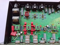
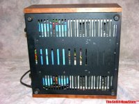
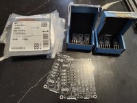
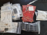
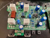
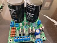
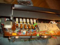
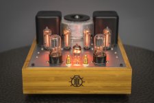
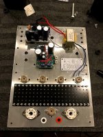
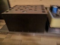
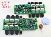
This is an amplifier I made a long time ago
But due to the parts at that time not meeting the specifications. I made it around 2012.
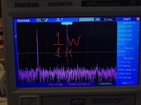
But the test results were very poor. So I have been improving it.
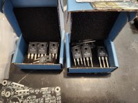
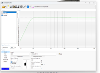
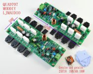
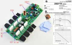
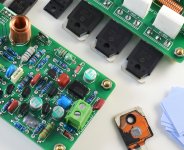
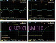
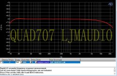
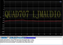
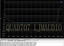
I have recently obtained some very good transistors. The test results in the new version make me feel very good.
It has almost the same performance indicators as the machines produced by QUAD's original factory.
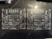
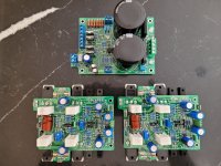
So I'm going to take the time to assemble it and listen to it myself. I will update the assembly steps.
of course. I am also an amateur businessman. I will provide it to others. But the condition is.
This product needs my approval. Otherwise, I will throw it away. For example, the QUAD707-2012 version. I have never had anyone sell it before.
But due to the parts at that time not meeting the specifications. I made it around 2012.
But the test results were very poor. So I have been improving it.
I have recently obtained some very good transistors. The test results in the new version make me feel very good.
It has almost the same performance indicators as the machines produced by QUAD's original factory.
So I'm going to take the time to assemble it and listen to it myself. I will update the assembly steps.
of course. I am also an amateur businessman. I will provide it to others. But the condition is.
This product needs my approval. Otherwise, I will throw it away. For example, the QUAD707-2012 version. I have never had anyone sell it before.
Attachments
-
 QUAD707-1.jpg321.7 KB · Views: 1,075
 -
 QUAD707-2.jpg392 KB · Views: 893
 -
 QUAD707-3.jpg279.9 KB · Views: 994
 -
 QUAD707-4.JPG544.7 KB · Views: 772
 -
 QUAD707-5.jpg115.3 KB · Views: 704
 -
 QUAD707-6.jpg102.7 KB · Views: 619
 -
 QUAD707-7.jpg152.2 KB · Views: 593
 -
 QUAD707-8.jpg144.7 KB · Views: 569
 -
 QUAD707-9.jpg119.5 KB · Views: 720
 -
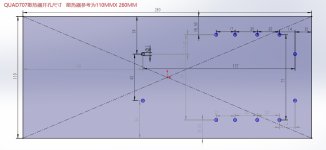 散热器尺寸图.jpg75.6 KB · Views: 722
 -
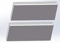 散热器尺寸图2.jpg53.8 KB · Views: 911