ESL Newbie questions...

Hi all,

me and a friend are going to build ESL after building "normal" speakers for centuries.
So far we've read a lot about ESL's. The more we read, the more questions we have... I gues you know what I mean 🙂
Anyway, we are going to build hybrid speakers, me i'm going to use a Ripol (since i am a big Open-Baffle fan) for the bass section, my buddy will use a closed box.
We decided to cross them around 200-250 Hz. If passive or active is not sure at the moment...
The panel size will be 285x900mm divided in 20-12-6-6-6-12-20 segments.
And here the questions start...
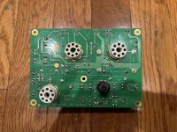
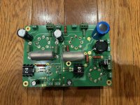
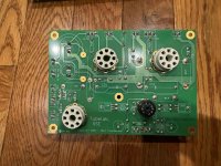
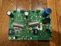
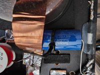
If we use aluminium profiles for the frame and also for the cross-braces and use duoble-sided tape 0,2mm for bonding the membrane to the frame, will there be enough insulation against the membrane and also the wires?
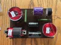
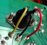
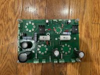
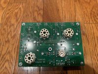
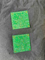
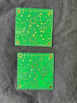
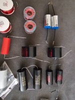
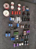
In the picture you can see that we tried two different sizes of ds-tape, one is 0,2 mm, the other one is 1.5mm thick. This was to check wether the braces will stick strong enough to the frame, unfortunately they do not. Next step will be to check wether glueing the braces with Sikaflex221 to the frame.
If we use rivets to fix the braces it is ok, but we lose the insulating effect of the frame material, this is a sandwich of aluminium and some plastic (here in Germany it is called Alucobond).
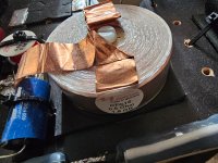
Don't mind the stator wires on the pictures, this was only to check how fast the glue is drying.

Another question concerns the distance from stator to membrane. Since the material we want to use for the frame was only available in 4mm and we want to keep things simple, the distance/gap between stator wires (outside of the insulation) is only 2mm instead of 3mm like described on the website of Steen Frank Jensen.
To be honest, to keep things simple we are going to copy his model since it is not that big.
We also like all the other stuff we have seen here in this forum but most these ESL's are too big.
Anyway we include some ideas from here in our building process...

So we are looking forward to your answers.
We are sorry for the chaos with the pictures... We couldn't find a way to delete the needless ones...

Best regards, Juergen and Dani
from Germany
IMG20240119130506_compress11.jpg
IMG20240119130529_compress62.jpgIMG20240119130506_compress11.jpgIMG20240119130529_compress62.jpg
IMG20240119130529_compress62.jpg

Tl494 Gate drive circuit design

Hello, i am trying to design a gate drive circuit with tl494, switching a gate drive transformer, which will switch two high voltage transistors on a half bridge power supply.
IMG_1096.jpeg

This is what i drew up then built, the switching transistors q1 and q2 are 2sc2655, with 33v 1n4752a diodes across them (hard to make out, i know)
At the moment i am trying to work out if its working properly. Its drawing about 0.2A of current at 24v from J1, which to me seems a little low for a gate drive transformer circuit…
This is the outputs of the gate drive transformer (secondaries) i measured.
IMG_1092.jpeg

IMG_1093.jpeg

Doesn't really look right, and im not sure what to think of the vpp.

Can anyone see anything wrong with my circuit , or that could be improved upon?

Using PSUD to optimise power supply in my KT120 amplifier

Hi folks! I acquired an old Luxkit A3600 push-pull amplifier a couple of years ago and I've enjoyed getting to know how it works, modifying it to take KT120 output tubes (from KT88s when I got it) and 6GU7s (in place of 6240G tubes that are long out of production). I've modelled the power supply in Duncan amp's PSUD2 application and wondered if anyone had advice about the goldilocks level of damping.

The original power supply consists of:
  1. a low DCR secondary winding labelled as providing 370V with max current of 400mA into
  2. a full wave bridge diode rectifier
  3. two multi-section caps (3x 47uf) split into:
    • 2x47uf then a 350mH (11ohm) choke coil
    • 2x47uf (provides B+ for KT120 output tubes) then a 2.2Kohm resistor feeds LTP phase inverter stage (twin triode 6GU7 tubes)
    • 1x 47uf then a 100kohm resistor feeds input signal preamp stage (twin triode 6AQ8 tube)
    • 1x 47uf then a 240Kohm bleeding resistor
I modelled this arrangement and tweaked the value of the last resistor, the capacitance values and the voltage at the secondary winding so they matched my voltage readings at each stage. I estimated the current at the output stage (4x 75mA fixed bias plus 4x 7.5mA for UL screen current) and at the phase inverter stage (2x 9.6mA constant current from shared resistor). I've estimated the inductance of the choke coil at 400mH because the current draw is 50mA below the 400mA current the choke measures at 350mH.

This is what I came up with:

1721735964870.png


I wasn't sure what to make of this so I did a bit of searching on the internet about optimising PSU components (shout out to DHTRob and many others) and created a new PSU model to make it faster and remove the overshoot and oscillation (see below).


1721736659380.png


Note that I increased the first resistor (R1) from 1Kohm to 2.2Kohm because I have recently moved house and I'm now experiencing a higher wall voltage. I can see from my PSUD experimentation that spreading out the capacitance across the amplification stages slows the power supply down, while front loading capacitance reduces ripple experienced by the rest of the amplification stages. The total capacitance in the stock configuration is 332uf and 451uf in the second model. The residual ripple for the output stage (I1) is less than half the stock config (1.3V vs 560mV diff min to max) and about the same for the phase inverter (I2) and input (R3) stages.

Do you think it is safe to try this configuration or should I reduce the capacitance of C2 and increase the capacitance of C3 and C4 to increase the damping and reduce ripple at those stages? Are there any stability concerns and what difference might I hear (if any)?

Endevco Signal Conditioner 133 frequency response

It seems, that I'm having an issue with my Endevco 133.

If I measure the frequency response w/o any sensor attached, it has a big bump between 40Hz and 60Hz. Other than that it seems to work OK.
As I bought it used from eBay some time ago, I can't say anything about the conditions it has been used in or about it's age.

Ideas/ advice would be appreciated.

Best
Stephan

Analog signal to HDMI input

Hi!
I am searching for possibility to organize analog input for a DSP with HDMI input only.
I am using miniDSP HDA (2x HDMI inputs, 1x HDMI output, 8x analog outputs) for my multi-way DSP based speaker system. Normally I am streaming simply from my computer. HDMI output is connected to a beamer, but is not always used, I can simply listen to music without a video.
Now I need an analog input for this system. Sound quality is not a real concern in my case, and I need only stereo. I have seen of course simple AV2HDMI or VGA2HDMI converters, but will they work without video input, maybe someone has expirience?
Or maybe you can help me with a way to do it?
Thanks!
Andriy.

HDMI/toslink multichannel 7.1/5.1 to usb audio out

I have various USB soundcards (7.1 channels) that I'm trying to feed with multichannel audio from my TV and console via HDMI or as a fallback Dolby Digital via toslink.

I was thinking of using my old raspberry pi 2B with some expansion board for HDMI/optical audio extraction or USB hdmi input device, if those exist. I saw some boards like hifiberry digi i/o and x6000 but they seem to only provide 2 channel input.

Does anyone know of a hat/shield/board for pi that could work or some USB device that could give me 8 channel input? I'm trying to build something that is not too expensive, shouldn't crack the 200usd bar 😉

Trying new LTSpice 24 - problems with .lib directive

Downloaded new LTPsice 24 today. I've been using LTSpice XVII).
In my sim file, have statement to load lib file from a URL:

.lib http://www.minek.com/lib/minek.lib

and it works perfectly fine with LTSpice VXII.

Of course it doesn't work in LTSpice 24. I'm getting error "Could not open library http://www.minek.com/lib/minek.lib".
Any ideas how to make this work?

Attachments

Introductions

Hi,
My name is Liam, I live in England. I work as music technician at a college. I do very basic repairs on instruments and audio equipment. I also have a music studio that I wired in but I’m trying to get into electronics so I can service my mixing desk and other audio gear in my studio. I’m looking for advice on equipment I’m trying to repair and here to gain general knowledge around troubleshooting equipment.

JLH 300 Series hiss

I recently come way from a charity shop with a pile of equipment which was only for sale as a job lot, after I spotted an interesting looking amplifier at the back.
It turned out to be a Hart Linsley Hood kit - Stereo 300 Series - and came with a pile of documentation too. It sounds fantastic, very powerful and controlled, but has what seems to me to be slightly excessive hiss. This is not affected by the volume control and is the same for all inputs, connected or not, shorted or open. It varies with the treble control, and doesn't affect the overall sound when playing music, but just seems a bit intrusive when just idling.

I was wondering if any experts could see anything in the design which would cause this; could it be ageing components or is it something I just have to live with?
Scan 1.jpeg

Recommended Books for starting out with Audio Electronics

Hi everyone,

I am starting out learning about electronics with a view to buy and restore non-working vintage audio amplifiers. I am looking for some good book recommendations to help me get started. I don't have a background in electronics or engineering, so some books that start at the beginning and walk through to more complex things would be great. Any thoughts? Be very interested to hear what people have found helpful.

Wiring an Alps BX2 balance pot

I'd like to replace the dual mono volume pots in my HV V2 with a stereo volume pot plus a balance pot. I know there are varying opinions on using balance pots; I'm not interested in that debate... Let's just say there are WAF considerations...

Anyway, I have the Alps BX2 balance pot pictured here. It seems to be uncommon, and I can't find any info on how to wire it in a preamp. The pot has 4 pins per channel, and I've included a schematic. I'm just having a hard time wrapping my head around how to wire it to attenuate one channel while leaving the other channel unattenuated. Any suggestions?

IMG_6761.jpg
IMG_6762.jpg

Introduction

Hello all!

My name is Pierre and i live in a little village outside of Gothenburg, Sweden, called Öxabäck. I am new to DIY audio equipment as I have always only bought it before and not solder it myself. In the recent year I have developed a taste to understand the underlaying function of the different parts needed to make an audio board work. The first one I made was the ProtoDAC TDA1387 x 8 that Moode have on their site. A fun little board that sound really good.

A few itterations later on that board I am now trying to learn I2S to use SPDIF/Toslink as input matched with WM8804 on a Raspberry Pi with my ProtoDAC as audio out.
Still got a long road ahead with a lot of reading and learning!

I hope I can get some help here when I get stuck in my studies 🙂!

Karlson-Cabinet 10" build for E-Bass-Guitar?

Hello!

My name is Flo. I am new to the Forum - and new to the whole topic of Speakers/Cabinets... (total NEWBIE)
I am putting this thread here because i read most of the Karlson-related posts here in the fullrange forum... hope im right.

I play electric bass guitar and want to build a speaker cabinet in the style of the Karlson/Karlsonator.
I do have skills in carpentry but not so much in elektrotechnical or acoustic/physics stuff :/
I hope you guys can help me out realizing my idea!

I already have a 10" speaker for my project - OBERTON 10B200
These are the specs/TSP:

https://oberton.com/en/?option=com_content&view=article&id=180:10b200&catid=49:ferrite-loudspeakers

Nominal Diameter: 10"/262 inch/mm
Impedance: 8 Ohm
Minimum Impedance: 5.25 Ohm
Power Capacity AES ¹: 200 W
Power Capacity ²: 150 W
Program Power ³: 400 W
Sensitivity: (200-2000 Hz) 93 dB/W/m
Frequency Range: 45 - 3000 Hz
Voice Coil Diameter: 51 mm
Voice Coil Material: Copper
Voice Coil Former: Kapton™
Voice Coil Winding Depth: 17 mm
Magnet Gap Depth: 7 mm
Cone Material: Glass Fiber
Basket: Die cast aluminiumMagnet: Feritte
Flux Density : 1.35 T

Resonance Frequency: 47.88 Hz
Mechanical Efficiency Factor (Qms): 9.27
Electrical Efficiency Factor (Qes): 0.341
Total Q (Qts): 0.329
Equivalent Air Volume (Vas ): 36.21 Litres
Diaphragm mass ind. airload (Mms): 43.75 grams
Voice Coil Resistance Re: 5.10 Ohms
Effective Diagram Area (Sd): 317.3 cm2
Peak Linear Displacement of Diaphragm (Xmax)*: ± 5.75 mm
Mechanical Compliance of Suspension (Cms): 0.252 mm/N
BL Product (BL): 14.02 T.m
V.C. Inductance at 1 kHz (Le): 0.84 mH

*First question would be if it is possible to put that speaker into a Karlson-Style cabinet and can it be tuned around 60Hz? (at least, this is what i was told to be "best" for bass guitar (when vented??)).
*Secondly i want to stack another, existing box of mine onto the enclosure (or/and other way around) - meaning that depth should ideally be 325mm(12.8Inch) and width 328mm(12.9Inch). Is it possible to just adapt the height to get to an useful result?
*Third - i want to "integrate" my existing amp into a recessed area on the back of the housing/cabinet. Here is a picture of my Ibanez"Promethean"-Bass combo...
i want to do it in the same way.
Promethean.jpgPromethean2.jpg

I really love the "looks/design" of the Karlsonator with its curvy acoustic lense/aperture and i was already looking at some fascinating stuff you guys are building here.
Also i found this guy @freddi on youtube who plays an electric bass through his selfbuilt xki-Karlson:
Login to view embedded media
Could someone please help me out to calculate/design the desired cabinet/box or point me in the right direction?

Greetings from Vienna/Europe
Flo

Klippel data interpretation, B&C's Xvar info value

What is the possible bleed of Bl(x) and Kms(x) values between each other with Klippel testing?

Looking at B&C Speakers 18DS115 with long coil and 14mm Xmax, things apparently look different than they are. The voice coil doesn't leave the gap till past 13mm travel one way, yet Bl falls rapidly in the graphs.
Also, at Xvar of 14mm, this beast is run past 20mm in their 2hr test, making it more IPAL-ish than conventional? What could we take from that? Could I use it safely past Xmax for short/peak use?

Introduction

I am not much on introductions, but my name is Craig. I work on electronics as a hobby and make noise with my guitar (probably doesn't qualify as music). I have worked on tube radios since I was a kid (1970's), these days several decades later I have a decent collection. Some of those date back to the early 30's. I am also an amateur historian, amateur radio operator... and for fun I am the mayor of the small town I am in. I get bored easily.

My guitar playing is similar to my radio repair hobby (actually I am much better at repairing vintage electronics). I have beat on a guitar since I was a kid, never mastered it, but I do it as a hobby, and as a result, I have a few old amplifiers (and some newer ones). Some of those amplifiers are of course tube type. I am about to rebuild my grandfathers old Silvertone 1472 that hasn't been used since his death in the 70's. I am also working on my first amp that quit and was placed in a closet.

I figured I would come here to see if I could learn anything and maybe offer something in return!

Using Ian Canada's modules with Audiophonics EVO-SABRE DAC Kit to the next level

My search started with wanting to integrate an ESS ES9038Pro board (see link below) to an RPI4 via the GPIO (I2S) but power the DAC with a good linear power supply instead directly off the GPIO.

ESS ES9038PRO DAC Module I2S XLR 32bit 384khz DSD with Screen - Audiophonics

When that came up empty I thought about this kit (see link)
AUDIOPHONICS EVO-SABRE DAC Kit DIY DAC 2xES9038Q2M Fully Balanced & Streamer for Raspberry Pi 4 - Audiophonics

However, I felt that they have shortchanged the project by not using a really good power supply for the DAC and feeding it off the GPIO. I also wondered about the clock. So I dug further and I ended up on 3 very long threads from Ian Canada on DIYaudio. (see links)

ES9018K2M, ES9028Q2M, 9038Q2M DSD/I2S DAC HATs for Raspberry Pi

Asynchronous I2S FIFO project, an ultimate weapon to fight the jitter

Develop ultra capacitor power supply and LiFePO4 battery power supply

The Audiophonics 9038Q2M kit above looks nice and slim but is only 300mm wide and 185mm deep and is not a full-width component (440mm wide) or deep (400mm deep) so I figured if one has a case that is 440x400mm instead of 300x185mm could one upgrade the kit using Ian Canada's modules listed below.

  1. FIFOPI Q3 ULTIMATE FIFO Reclocker
  2. LINEARPI DUAL Ultra-Low-Noise Linear Power Supply
And maybe a SheildPi. (is there a link for this)

To keep the height to 55mm I would use a 40pin cable instead of stacking the boards.

A second option would be to use all parts from Ian Canada but I am not sure what this list of parts would be. He has a long list of modules and options.

Maybe
  1. FIFOPI Q3 ULTIMATE FIFO Reclocker
  2. LINEARPI DUAL Ultra-Low-Noise Linear Power Supply
  3. The elusive ShieldPi (I can't find a link for this board)
  4. Dual Mono ES9038Q2M DAC HAT
  5. ESS SABRE 90X8 controller with display

and maybe
TRANSPORTPI Digital Interface SPDIF Low Jitter
RECEIVERPI Digital Interface I2S SPDIF

Can anyone point me in the right direction? Thanks.

Powerful SMPS for tube ampifier

Hello, I designed a SMPS that creates 0 audiable noise in a tube ampifier. Originally this was a school project for a competition but things did not work out quite the way.

The powersupply steps up 10-30V input to whatever output voltage you desire up to the volate rating of the filter capacitor (1kV best estimate of the highest voltage). I have tested the powersupply on a resistive load and I managed to test at 450V 50W without any issues. The tube amplifier I tested the supply on is a well known 20W Mullard amplifier. The amp consists of a pair of EL34s a 12AX7 inverter and driver and a EF86 as the preamplifier. The onl change I did was to use a EF0 instead of the 86, and even it being a very microphonic tube does not create any issues whatsoever and it sound amazing. I designed the amplifier on a PCB and the powersupply too.

Right now the powersupply its been about the third prototipe, has a small issue so without a fan blowind lightly on the switching transformer an the heatsink of the IGBT, gets unbareably hot and the input filter cap too so I guess it acts as some sort of weird oscilator - I havent looked into it any deeper yet I was more interested to hear the amp.

What I would like to know, if there is anyone even lightly interested to see a switching powersupply for a tube amplifier. The current version creates the 410V for the amplifier from anywhere between 12 to 30V. It is also possible to use a different switching tranformer for rectified line votages- why would I use a swtiching powersupply istead of a regular simple transformer on the line voltage? Lets say the voltage if tightly regulated and stable-and this powersuppply is MUCH cheaper than the transformer itself.

Little about myself- Im a students I turned 17 last week and I was protiping this SMPS for about 6 months before i I got to a point of any real useable result. I made lots of amplifiers mostly transistor based or IC based AB amplifiers and Im also into analog technology. So basicaly a nerd 😀

I apologise for the grammar im not a native speaking.

If anyone is interested in any measurements I can do them I do have a digital scope and other testgear to do almost any mesurements I can think of except EMI and interference measurements

Illustrated guide to the 4U deluxe Chassis

Illustrated guide to the 4U deluxe Chassis


This is a visual guide to the assembly of the diyAudio 4U Deluxe Chassis. The “Jack of all Chassis”.

It has a pre-drilled back plate and pre-drilled and tapped heatsinks. The heatsink drill pattern is the diyAudio “Universal Mounting Specification” and the back plate has holes for input RCA jacks, Speaker jacks and a Power Entry Module that contains IEC mains inlet, power switch and fuse holder.

This chassis is ideal for the HoneyBadger, F4, F5, Aleph J, or Burning Amp. (The BA- with just one PCB of output transistors/channel)
It could also be used as the chassis for a Monoblock F5Turbo v2 or a Burning Amp with 2 PCB of output transistors.

Lastly this chassis has the “DIY-friendly baseplate” a sub-floor that has a grid of 10x10mm holes making no or little need for drilling holes to attach most of your components to the chassis. You will find that with just a little planning you will commonly need only to widen one hole to accept the mounting bolt for a toroidal transformer. Everything else can be mounted with the existing holes.

The chassis is also compatibletable with the diyAudio Chassis Riser system, allowing for more area to mount whatever your project may require.

Much more information may be found here -

Deluxe 4U "Jack of all Chassis" (All Aluminum) - Full width with 40mm Heatsinks - Chassis

Let’s look at the contents of the package -

IMG_2190.jpg

Feet and hardware.

IMG_2194.jpg

Heatsinks.


Top and bottom plate. These are custom aluminum, with an extra row of vents per side.

IMG_2192.jpg

Back panel.

IMG_2195.jpg

10mm custom front panel. Obverse.

IMG_2196.jpg

Front panel reverse. This is a custom part made for diyAudio with the array of holes shown - these are all blind, but most are tapped. For example you can attach the V3 PSU circuit board vertically to the front panel, or attach a riser plate. The bottom centered offset hole can be drilled out for a power indicator LED. Other holes are there to accommodate handles. I’m sure there are many ways to utilize these attach points that the community will discover.


These rails are the mechanical heart of the chassis. They attach to the heatsinks, and then everything attaches into them.


DIY-friendly perforated baseplate.


Everything.


The logical place to start is here, with the rails and heatsinks.
(sometimes there is streaking from the cleaning process. It makes no effect on the efficiency of the heatsink, and is quite smooth.)


Bolt the rails to the heatsinks, but leave the screws a little loose.


The next pieces will be the back and front panels.


Locate the back panel and this hardware.


Attach both sides as shown.


You should have this assembly when done.


Align the front panel and your assembly as shown.


Attach here with this hardware.


Looking good!


Next the perforated base needs to be installed. This is the hardware provided.

IMG_2224.jpg

It attaches into these countersunk holes in the bracket.


Using the supplied hardware it is intended to attach with the lip up


Which will give enough clearance in-between the black aluminum baseplate at the perforated base to clear small screwheads.
I like to mount it with the lip down, giving enough clearance to clear the through-bolt of a toroid transformer, but it requires some alternate fasteners. (See below for more information.)


Perforated base installed.
Now is a good time to snug all the screws and square the chassis as best you can.


The top and bottom panels are identical, but there is a front and back - but as the holes will align in only one direction, it is easy to determine.

IMG_2230.jpg

The top and bottom panels attach with the sheet metal screws provided. It is a much stronger interface that you would think, regardless the strength is all in the brackets.

IMG_2231.jpg


IMG_2232.jpg


IMG_2236.jpg

Start of multi-way project. Help with choosing

Good morning everyone.
I have just finished my no compromise subwoofer project composed of Faital pro 18XL 1800 thanks to your precious advice. So now I can do nothing but finish the job by also building the speakers.
I have a lot of work to do. At the moment, as a system, I have a Sabre Topping D90 III dac, a Topping Pre90 pre, an Audiophonics ET400A Purifi power amplifier and a Powersoft power amplifier with Loto DSP and 2 Litemod 2ch modules.
currently the towers (PL200 audio monitors) are moved by the ET400A purifier while the subwoofer by a single BTL powersoft module.
I could use 2 more channels to harmonize the subwoofer with the woofers in the project I will realize.
The project will be in pneumatic suspension. Speakers divided into medium-high and low sections. Woofers (2 per speaker) separated from the medium-high range. I am looking for high efficiency, precise, fast, dynamic components. In short, the best you can have while remaining within human figures. I am not very expert in transducers, so my research was very limited.
For the low end of the project I had considered the FaitalPRO 10FH520 16Ω x4 (16 ohm because they will be connected in parallel, but also because compared to the 8 ohm version these can be put in pneumatic suspension, while the 8 ohm ones unfortunately cannot).
Midrange FaitalPRO 6PR160 8Ω d'appolito configuration x4.
and for the high end the Beyma TPL 200.
The main doubts concern the integration of the Faital midrange with the Beyma AMT. From its MMS of 12.5gr (FaitalPRO) it seems that it can keep up with the Beyma.
But as I said before I am not sure because I am ignorant on the subject.
I chose the rest of the components left in Faital for a familiar sound problem, but I have no problem changing brands if there are better drivers that can work with high efficiency air suspensions.
I had thought of putting a wide band as the medium, limiting the band to the medium one. the fostex fe 168 ez sigma drivers. But I didn't know if it was a good idea.
I also have to choose whether to make a passive crossover filter or buy an active one. They say that the passive one is better.
The type of speaker must be a tower, trying not to exceed 1.30 meters in height. and I would like to stay flush with the transducers in width. While I can have margin in depth.

CEC TL3 - TOC recognized but sometimes lengthy table of contents, depending on the original CD

Hello, I have a relative who entrusted me with a CEC TL3 because the player was having problems recognizing the table of contents with two of these Cds, which are originals (not CD-Rs). After dismantling the unit, I found three cut chemical capacitors (330µf/6.3v) on the power supply board. I also took the opportunity to replace the three 47µf/50v close to the heatsinks. I didn't find any other chemical capacitors out of order on the power supply board. I should point out that the laser lens was cleaned in two passes (isopropyl alcohol). After reassembly and tests with several Cds, including the one that was not recognized, there is some improvement, but it's still not optimal. I'm thinking of checking the servo card settings and readjusting only if necessary. For this, I'll need the CEC TL3 manual service. The servo card has two markings on the PCB (TK-T71 94V-0) and (4B10012700C). I'll post a photo soon. Thanks in advance to anyone who can give me a hand.

power supply base on Pass Labs X2

I want to build the regulate power supply base on Passlabs X2's power supply.
The original on use two transformer to form a network of four 40volt rails attached in series and feed to the regulator as show in pic#1
For mine, I wanna use only one transformer. So, may I use the schematic as shown in pic#2. the 2 seconday form 40volt and 120volt rails to feed the regulator to get the same regulated voltage.

My quesion :
  • Is there any difference between two of this in term of performance? apart of using higher voltage cap.
  • Can I use IRF610 mosfet instead of IRFP240 for the plus voltage rail? since the the current draw from the psu is about 60mA. Is there a special reason why IRFP240 is picked for this job?

Thank you.


org.png


sim.png

Mission Cyrus Integrated Amplifier Series - various DC Sockets/Plugs for PSX - Overview wanted

According the attached images there are in use different DC connector versions for the outdoor power supply - not only dependent of the model and the age.
4-pin DIN- and XLR versions I note, so as a blue version from Hirose.

Who can upload the whole overview of all used brands and types ?
Thank you very much.

P.S.: The blue socket on PCB from third and fourth image seems to be a HRS (Hirose) RPC2
https://in.element14.com/hirose-hrs/rpc2-12rb-3p-71/plug-chassis-3pole/dp/1077726
https://in.element14.com/c/connecto...IkPXrOiQPIqa71CYuHfX_wVg3NAgSYUHf8Fm-b6ifV3VY
https://uk.farnell.com/hirose-hrs/r...lMXJkXeNffff-UbqayHKFkQLoXvmtmmmDoFJndGNxKsUf
Unfortunately no longer available

Attachments

  • Cyrus-PSX-002-768x431.jpg
    Cyrus-PSX-002-768x431.jpg
    56.4 KB · Views: 63
  • Cyrus-PSX-003-768x473.jpg
    Cyrus-PSX-003-768x473.jpg
    74.5 KB · Views: 55
  • Cyrus_II_version3_nichicon_muse.png
    Cyrus_II_version3_nichicon_muse.png
    630.3 KB · Views: 47
  • cyrus_2_amp_revision_01.png
    cyrus_2_amp_revision_01.png
    481.3 KB · Views: 47
  • Cyrus-DC-Socket.03-300x284.jpg
    Cyrus-DC-Socket.03-300x284.jpg
    21.4 KB · Views: 51
  • auditorium-cyrus-psx-r.2-netzteil-287207-images-2_1920x1920.jpg
    auditorium-cyrus-psx-r.2-netzteil-287207-images-2_1920x1920.jpg
    97.5 KB · Views: 54
  • Cyrus_II_version1_back.png
    Cyrus_II_version1_back.png
    370 KB · Views: 51
  • Cyrus_II_version1_back_PSX.png
    Cyrus_II_version1_back_PSX.png
    556.7 KB · Views: 48
  • images.jpg
    images.jpg
    10.8 KB · Views: 49
  • HRS (HIROSE) RPC2.pdf
    HRS (HIROSE) RPC2.pdf
    141 KB · Views: 36
  • Like
Reactions: drmaftoon

Introduction

Hi, I’m Phil. I have been into HiFi since about 13yo (1970’s). My uncle was a TV and Audio engineer. He was semi retired and working from a home workshop that seemed like an Aladdin’s cave! He gave me an old valve radio that I set up at home with a long ariel. I think the warm sound, the heat, and the glow of the valves got me hooked. I’m retired now myself and hope to learn enough about electronics to fix up some equipment, and maybe build some kits.

MB112-II purple light

Good evening good people,

I just bought a secondhand GK mb 112 ii. It had the pink/purple led (instead of the normal blue) on the power button, which indicates a fault, but it still worked fine and sounded good, so I took a gamble on it (I got it for around 150$). I'm trying to troubleshoot the amp and hopefully make it as good as new. So far what I know:

- The amp's manual states : "Smart Protection Circuitry: The MB Series protection circuitry constantly monitors for unsafe operating conditions such as short circuits, miswired speaker cables, blown speakers, improper ventilation, and incorrect speaker configurations. In addition, protection is provided during power up/down. If the MB Series senses any unsafe operating conditions, the output signal is immediately muted and the power light changes from Blue to Red. The amplifier will remain muted until the fault is removed. Be sure that you are not exceeding the maximum recommend load described in this manual. If the problem persists, contact GK directly for technical advice."

No info about purple light, or if it can still work if the protection circuit detects a fault.

- When I plug a bass, turn the amp on, I get sound. When no bass is connected, there's a very low hum, that is (very) slightly affected by the gain button and the -10db pad and moderately affected by the treble control.

- I tested the speaker on my guitar amp too and it works perfectly fine.

- The phones output is not working. I wonder if the purple light can be caused by a faulty headphone circuit ? If it’s the case, I can totally live with that.

- The DI output does work, but I can hear some static on the recording.

This is my first attempt at repairing an amp. I think it would be a good learning experience. If all fails, I'm gonna turn it into a cab. Any help would be appreciated.

Thank you

New member elrjay

Hi All. I am a new member from Australia and found many links to articles on this site while I have been repairing musical amplifiers in recent times.
My interest in electronics started around 50 years ago when I was building small DC power supplies and music effects devices - all discrete components.My "old" 6w valve amp from 60 years back is now in vogue! But then I got into solid state transistor powered amps - made a couple of 100w kits all good.
I have been a guitar and bass player for even more years. Since retiring from professional work, I have recommenced my interest in the same equipment but with many "new" components. I have had a few repair successes and have a few projects for further work.

All-DHT amplifiers: no indirectly heated signal tubes!

This thread has the goal of collecting schematics, pictures and comments of any kind about amplifiers where ALL the signal tubes are directly heated - both input and output tubes. The only indirectly heated tubes allowed will be in the power supply or support positions e.g. rectifiers or active loads. Can be push-pull or single ended, and directly heated pentodes are also allowed, in triode or pentode.

Since the majority of directly heated tubes are fairly low mu (up to 15) it is likely that designs will include 3 stage amplifiers or 2 stage amplifiers with step-up transformers in the input or interstage. Maybe also some other creative solutions.

So please post your ideas, schematics and comments of any kind and let's make this thread an interesting one!

To kick off, here's a design by Ale Moglia titled "300B SE Amp: 47 Driver: Going DHT end to end"

https://www.bartola.co.uk/valves/2020/07/25/300b-se-amp-47-driver/
  • Like
Reactions: Pano

On sparse speaker arrays

Even the best loudspeakers sound quite poorly in nowadays squeezing living rooms. The problem of room reverberation can be addressed by extensive soundproofing and/or by using very directional loudspeakers - but covering the walls and ceiling with class A acoustic foam is not cheap & utterly destructive to the peace in the family; commercial controlled directivity loudspeakers cost a fortune while developing your own without an anechoic chamber nearby is unrealistic. However, in some situations it is possible to use the room geometry to reduce room reverberation and improve the listening conditions.

Introduction​

Let’s consider an alternative as sparse (3…6 drivers) speaker arrays positioned in the room corners so that the floor & ceiling of a typical room create a tall virtual column. The driver’s height is defined by

gap=(C2F-H)/NS; aH=(0:NS-1)'; aH=aH*gap+gap/2;

where C2F is ceiling-to-floor (typically 9’, ignoring 1’ of ceiling space for pipes, etc) height, NS is the number of drivers, and H is the ear height for a sitting listener (typically 2’8” … 3’). Drivers shall be focused (arched and angled, as per near-field beamforming) onto the DIYer and his ever-grateful family at 9’…11’. In (a simplified) theory, such array shall have wide horizontal dispersion and its impulse response (on the axis) shall look like
rir-6.png


with floor and ceiling reflections interleaving, each having a small (~1/NS) relative amplitude, with loudness decaying as (1/sqrt(distance)), contrary to (1/distance) for point source loudspeakers. However, I could not find any published (by others) real-world measurements, to either confirm or disprove this theory. Thus, I measured what I could myself. Of course, the results are specific to the room & drivers – but something, even little, is better than nothing.

Methods[1]

This design and measurements are concentrated on midrange applications, 300Hz – 3kHz, of the maximal sensitivity of human ear to the Direction of Arrival (DoA).

The drivers are Dayton Audio Sig150-4 mounted in approx. 3.6L boxes angled 60⁰ inwards, which boxes are mounted on a long plank which is mounted into the corner of a somewhat spartan room 25’ x 14’ x 9’. Multiple drivers were connected in series.

P7130004.jpg

P7130006.jpg


The amplifier output was set to get 80 dB SPL @1m from a single driver. A (pre & post) calibrated 12 dBA cardio microphone on 2i2 Gen 3 USB audio interface was used. Room Impulse Responses (RIR) were obtained by a regularized Exponential Sine Wave (ESS) method Loudspeakers for AEC: Measurement and Linearization - File Exchange - MATLAB Central (mathworks.com) (to be updated).

The RIRs were postprocessed to extract the Direct to Reverberant Ratio (DRR(f)) as the Y-value that the polynomial approximation of the corresponding normalized reverberant slope(f) crosses at X=0:
rir-drr.png

Obviously, speakers’ arraying does not affect RT60(f).

Measurement distances are 100:50:400 cm, with 300cm as target. The default measurement height is 85cm, to be varied 70:5:100cm. The first 20ms of RIR, DRR, arete (top of the ridge) of wavelet-transformed RIR, and total FR are considered to be more important than other metrics.

Results​

number of drivers [h->1, n->3, m->4, n->5, j->6] summary​

rir-13456-300-85.png


fd-13456-300-85.png

At target distance & nominal ear height. See the details below.

Single Driver​

rir-1-distance.png


fd-1-distance.png


Red lines are for quasi-anechoic conditions (alas, wrong polarity).

6 drivers​

Variations of Listener’s Distance​

Here and below, red lines are of a single driver at 300cm, as the reference.
rir-6-distance.png


fd-6-distance.png


Variations of Listener’s Ear Height​

rir-6-height.png


fd-6-height.png


5 drivers​

Variations of Listener’s Distance​

rir-5-distance.png


fd-5-distance.png


Variations of Listener’s Ear Height​


rir-5-height.png


fd-5-height.png

4 drivers​

Variations of Listener’s Distance​

...oops, only 20 images
Variations of Listener’s Ear Height
3 Drivers
Variations of Listener’s Distance
Variations of Listener’s Ear Height
6 drivers, straight line [e] vs angled only [f] vs arched only vs arched and angled [j]
rir-angled-300-85.png

fd-angled-300-85.png

As usual, [h] stands for a single driver as baseline.

Other Observations​

  • The measurements show only 10 dB of improvements in DRR but subjective perceptual improvement is much stronger, far beyond expected.
  • Due to 15.5 dB lower SPL at each driver, non-linear distortions and Barkenhouse noise are proportionately lower.
  • The dynamic range widens, high SPL are not distorted.
  • The (1/sqrt(distance)) effect is realized only partially per measurements but nearly fully by perception.
  • Judging by ear at 10’, 6 drivers with 90dB SPL @ 2.83V sensitivity are louder than a 110 dB SPL single driver, ~same Z.

Discussions​

Many more drivers & configurations were built and measured in the last year. None of them contradicts the data above, and these have relatively low additional meaningful information and were omitted to avoid overloading readers.

TBD

Conclusions​

  • Sparse speaker arrays are a compromise. Particularly, they are not a good fit if you require that listening experience shall be invariant to ear’s height. Left/right/closer/farther are not a problem.
  • You do not need 20 drivers / column to realize line source advantages.
  • You do not need near-perfect expensive midrange drivers to get decent sound.
  • You do not need 400W amplifiers, for sure. Even 100W is too much.
  • An average DIYer can build a sparse speaker array and adjust it to his preferences without getting into much expense or serious technical difficulties.
GNU General Public License v.3+ https://www.gnu.org/licenses/ applies to all information provided.


[1] Disclaimer: The objective measurements below are somewhat related to but do not characterize human auditory perception to any highly disputable degree of fullness or precision.

Attachments

  • rir-6-distance.png
    rir-6-distance.png
    23.2 KB · Views: 51
  • fd-6-distance.png
    fd-6-distance.png
    36.4 KB · Views: 50

Another interesting Aluminum clad horn tweeter active loudspeaker from Oz

cast-speaker-tom-fereday-piit-giblin_dezeen_2364_col_3-scaled 2.jpg


Not the usual source, an Architectural “magazine”. Looks like a waveguide, which has one asking, “Midrange?” but there is a short c0omment at the very end that suggests it is an MEH, but the second picture (and the makers bumf) suggests something else. Pretty cheap given the amplifiers come with (if pricng is /pr)

https://www.dezeen.com/2024/11/05/aluminium-cast-speaker-tom-fereday/

tbij4vofyQsG6RQncButgU-1600-80.jpg.png


Pitt & Giblin: https://www.pittandgiblin.com.au/cast

More coverage:
https://www.wallpaper.com/tech/cast-aluminium-speaker-tom-fereday-pitt-giblin
https://leibal.com/products/cast/
https://www.gessato.com/cast-aluminum-speaker/

dave
  • Like
Reactions: AllenB

S. Harsch XO

This work started in the Filler Driver thread. I was studying transient XO's and built a test bed speaker to quickly test out new XO ideas with miniDSP. Here is a photo of my test bed. It is a basic open baffle for ease of construction and has a pair of Eminence Beta 12cx (no CD, with coax horn sealed up), a pair of PRV 5MR450NDY mids, and a PRV D280Ti with a PRV 45x45 deg waveguide. These are all fairly efficient drivers and are what I had on hand. The amp is provided by TDA7498 100w class D amps powered by 19v (mid and tweet) and 24v (woofers) SMPS bricks.

494160d1437200618-filler-driver-ala-b-o-gen2-beta12cx-5mr450ndy-d280ti-front-photo.png


I first started with the B&O XO which requires a wide bandwidth mid that is band pass filtered with 1st order Butterworth and straddled on either side with a LR2 filter for the woofers and tweeter. I was then turned onto the XO topology proposed by Samuel Harsch by member Phase_Accurate. The paper is in French but I figured out that the basics are:
1. Set the low pass filter for the woofer as a 4th order Butterworth at central frequency, fc for the XO centerpoint.
2. Set the high pass filter for the tweeter as a 2nd order Bessel at fc.
3. Set the delay of the tweeter equal to 1/2 of the period of one cycle at fc.
4. Use all positive phase on woofer and tweeter.

Here is an example of the XO plot from the Harsch paper:
494790d1437489518-filler-driver-ala-b-o-harsch-xo-plot.png


Here is the step function from the above XO as predicted by Harsch:
494791d1437489518-filler-driver-ala-b-o-harsch-xo-sr-plot.png


So I tried it out on my 2-way 10F/8424 & RS225-8 FAST Ref Monitors and got this for the XO plot:
495043d1437630819-10f-8424-rs225-8-fast-ref-monitor-harsch-10f-rs225-xo.png


For the 10F/RS225 FAST, this was the corresponding measured Step Response:
495046d1437630819-10f-8424-rs225-8-fast-ref-monitor-harsch-10f-rs225-sr.png


For the 10F/RS225 FAST, here was the measured phase (notice the little bump at the XO frequency as predicted - but no wrap):
495044d1437630819-10f-8424-rs225-8-fast-ref-monitor-harsch-10f-rs225-phase.png


For the 10F/RS2225 FAST, here was the measured group delay, not over 5ms above 40Hz:
495047d1437630819-10f-8424-rs225-8-fast-ref-monitor-harsch-10f-rs225-gd.png


What the Harsch XO does nicely is that it allows one to use a steep XO to block out the nasty cone breakup on a woofer with a high order filter. Yet still not have a large phase wrap in order to maintain a time aligned transient perfect response.

So I got to thinking if this can be applied to a 3-way by mirroring the XO topology. That is Butterworth 4th order for the low pass on the woofer, Bessel 2nd order for the mid high pass and Bessel 2nd order for the mid low pass (or Bessel 2nd order bandpass for mid), and a Butterworth 4th order for the tweeter high pass. So what this means is that pretty generic components can be used in that a special wide band mid is not required anymore as the filter is already a fairly steep 2nd order. And for the woofer and tweeter, we can use 4th order filters which are great for controlling distortion, and preventing cone breakup leak-thru from the woofer.

As I had a 3-way XO test bed already handy, it was just a matter of putting the XO settings into miniDSP. So here is the electrical XO I implemented in miniDSP:

495707d1437975878-s-harsch-xo-harsch-3-way-minidsp-xo.png


And here is the resulting acoustic XO that was measured (yes the SPL levels are fairly low so that I did not wake up the family during sweeps). As you can see, the curves are fairly common and innocuous. The 1st order textbook curves of the B&O were especially hard to achieve in practice. With the Harsch topology 2nd order and 4th order are much easier to get. The tricky thing is what to do for the time delays? Well, it is exactly the same delay assuming driver acoustic centers are already time aligned. The mid needs to be delayed from the woofer by 0.5/fc_low and the tweeter needs to be delayed from the mid by 0.5/fc_high. For my case, I used a 500Hz and 3500Hz XO points:

495708d1437975878-s-harsch-xo-harsch-3-way-xo.png'


Here is the resulting Impulse Response:

495709d1437975878-s-harsch-xo-harsch-3-way-ir.png


And here are the resulting Step Responses - I know there is a little pre-rise but overall it is much better than a jumbled up-down-up-down mess you would see with an all LR2 or LR4 XO:

495710d1437975878-s-harsch-xo-harsch-3-way-sr.png


This is still a work in progress. Does anyone see any problems with it? I think this works. I am still having a problem getting the phase to be wrap free - it seems to wrap at the centeral frequency and not at the low and high XO frequencies. Anyhow, still debugging it. This XO may be useful for folks looking for an easy to implement quasi-transient perfect XO using IIR filters in DSP. How does it sound? Fantastic! My speakers are essentially 98dB sensitive and super loud and clean with this XO. I am really enjoying the sound and how the percussive sounds like guitar and drums really have a "live" feel to them.

Attached are some sound clips (stereo recording using Zoom H4 of the mono- Right channel playing). Change file extension from .asc to .mp3 in order to listen.

Attachments

  • harsch-3-way-miniDSP-xo.png
    harsch-3-way-miniDSP-xo.png
    104.6 KB · Views: 13,393
  • harsch-3-way-xo.png
    harsch-3-way-xo.png
    86.6 KB · Views: 14,771
  • harsch-3-way-ir.png
    harsch-3-way-ir.png
    40.1 KB · Views: 12,724
  • harsch-3-way-sr.png
    harsch-3-way-sr.png
    72.5 KB · Views: 13,081
  • harsch-3-way-clip-1.asc
    harsch-3-way-clip-1.asc
    1.7 MB · Views: 348
  • harsch-3-way-clip-2.asc
    harsch-3-way-clip-2.asc
    1.7 MB · Views: 287

Office Build Thread Version 2 - things changed...

Alright so we are here again. Originally I was going to run only run two monitors in this new office but I need to go to three. I could move the monitors aparts by maybe 5 inches but that will make working harder. More head movement.

So yeah, once I actually got in here I realized the 3 way I was making is just going to be too large for this work area.

What build would you make for this setup? I really want a three way but I don't think that is possible unless I mount the speakers on the wall above the monitors. I could put them on adjustable arms have them pointed down at me. The window kind of gets in the way of that.

I really don't want to be boring and put a couple 3" Mark Audios in some spherical enclosures underneath the monitors pointed up at me.

Anyways, let me know what you'd do if this were your new space

Attachments

  • PXL_20241106_210448003.jpg
    PXL_20241106_210448003.jpg
    443.8 KB · Views: 62
  • PXL_20241106_210443030.jpg
    PXL_20241106_210443030.jpg
    451.1 KB · Views: 54
  • PXL_20241106_210444736.jpg
    PXL_20241106_210444736.jpg
    294.5 KB · Views: 55
  • PXL_20241106_210446119.jpg
    PXL_20241106_210446119.jpg
    543.1 KB · Views: 63
  • PXL_20241106_182501813.jpg
    PXL_20241106_182501813.jpg
    424.8 KB · Views: 57

XSim free crossover designer

I'm announcing the public release of XSim, a "free-form" Windows-based passive crossover design and simulation program intended to be as intuitive and non-restrictive as possible. . The program is ***free*** for personal or commercial use. Any speaker builder with at least a basic understanding of what resistors, capacitors, and inductors do, and with decent response measurements (FRD and ZMA) of their drivers in their boxes, should be able to get useful results right away.

download from:
http://libinst.com/Xsim/XSimSetup.exe

Experimenting with "ideal" driver data (the default for each driver) can also be fun and helpful in understanding the effects of various circuit types. Some built-in multi-part "Circuit Blocks" also provide for basic pre-configured circuits to be tuned per their overall parameters (Q, corner frequency, attenuation, etc). There are "Example" files inlcuded in the XSim download (currently less than 1.5MB) as well.

XSim allows you to see simultaneous multiple graphs of your choice, including impedances, voltages, power consumptions, group delay, and frequency, impulse, step, and square wave responses. You can watch the performance and/or stress on any part vary as you tune structure or component values in real-time. The circuit network is re-solved automatically with every change you make.

The "free-form" aspect of XSim is that crossover designs are unrestricted, no particular circuit structure need be used. Essentially any R-L-C passive network you can think of can be easily entered using graphical schematic entry, with results calculated as you design. A common "ground" node is provided, but its use isn't required.

screenshot2.png


Circuit designs (incuding all in included driver data sets) can be shared by email or forum post in XSim's ".dxo" format.* Graphic files can also be saved in standard picture file formats.

Stuff yet to come: [edit: the following aren't actually going to happen now, as it is too much work to herd vendors into getting this info together and hosting it on their sites!]
The release version of XSim featiures automatic downloading of part and driver information based on vendor and part number, making it easy to find and order what you need to turn your design into working hardware. However, no vendors are as yet signed up to provide XSim access to part or driver information. XSim will be able to download these lists itself, when available. XSim can also update its own program (with owner permission) so people who use it online can always be up-to-date. ...And so I can add or fix features without asking you to deal with downloading and installing each time.

XSim does not yet include geometric features (such as varying mic position, baffle or boundary-bounce effects) as in Jeff Bagby's very successful "PCD" and other programs derived from it. But that is in the works, with some assistance from Jeff. There are also as yet no box-design features, but this is also planned so that full designs can be worked with using the infinite baffle data provided by vendors. [these might still happen, when/if I get back into programming and study mode 🙂 ]

edit: * as it turns out, this forum doesn't let you attach the .dxo files (or other files it doesn't know about). So you'll have to first zip the file and then post the ".zip" file containing the ".dxo" file. On downloads, do the opposite: unzip and then open the .dxo file into XSim. Maybe someday we can get diyaudio.com to let these files be attached? They are only text, no way for a virus to sneak onboard one of them!

Added Nov 2017: There is a procedure summary for collecting and adjusting driver FRD data for correct relative delays (which you need to accurately simulate crossovers) here -- XSim free crossover designer
  • Like
Reactions: emailtim and gupsta

Introduction from UK

Hi all,

Audio well where do I start?
Grown up in a music cafe with Saturdays live music created interest at a very young age
Then when 16 became a FOH Sound Engineer in the late 70s so all ANALOG gear 🙂 but of course moved over to Digital

Other hobbies are electronics, audiophile, sea sailing and mostly computing as work next to FOH

My Audio start time was mostly McIntosh, Crown, Altec & JBL and later T+A

Current having Urei speakers (love point source) and Tube Amps with one SE EL84 from the late 60s or may be 50s and a Croft Phone Integrated (8 EL84)

For Sale Tubelab SSE, 2x Simple SE, TSE-II, populated

Various Tubelab populated PCB Board for sale.

I populated them with quality parts, then never completed the builds.

They should all be working, but you may want to double check them in case I made any mistake on them.

  • 1x Tubelab Simple SE (dated 2006, no cathode resistor installed), $100
  • SOLD: 1x Tubelab SSE (dated 2012, 680r cathode resistor installed), $100
  • 1x Tubelab Simple SE (setup for KT88), $100
  • SOLD: 1x Tubelab TSE-II (set up for 300b)
  • SOLD: 1x Tubelab TSE-II (set up for 45, photo attached), $100
  • SOLD: 1x Tubelab SSE (dated 2012)
  • SOLD: 1x Tubelab TSE-II (dated 2020)
  • 2x Tubelab Universal Driver Board PCB 2015, new unused $30 each

Need to add shipping from Brooklyn 11211.

Accepted payments:
  • Zelle
  • Paypal (add 3% fees if "as purchase")
  • Venmo (add 3% fees if "as purchase")
  • Revolut
  • Wise

Thanks

Attachments

  • IMG_5185 2.jpeg
    IMG_5185 2.jpeg
    583.4 KB · Views: 176
  • IMG_5186 2.jpeg
    IMG_5186 2.jpeg
    568.8 KB · Views: 151
  • IMG_5188 2.jpeg
    IMG_5188 2.jpeg
    531.5 KB · Views: 161
  • IMG_5190 2.jpeg
    IMG_5190 2.jpeg
    556.6 KB · Views: 154
  • IMG_5191 2.jpeg
    IMG_5191 2.jpeg
    164.1 KB · Views: 160
  • IMG_5192 2.jpeg
    IMG_5192 2.jpeg
    158.8 KB · Views: 158
  • IMG_5193 2.jpeg
    IMG_5193 2.jpeg
    566.9 KB · Views: 173
  • IMG_5194 2.jpeg
    IMG_5194 2.jpeg
    548.9 KB · Views: 173
  • IMG_5195 2.jpeg
    IMG_5195 2.jpeg
    578.9 KB · Views: 185
  • IMG_9200.jpg
    IMG_9200.jpg
    572 KB · Views: 60
  • IMG_9200.jpg
    IMG_9200.jpg
    601.1 KB · Views: 60
  • IMG_9507.jpeg
    IMG_9507.jpeg
    1.1 MB · Views: 46
  • IMG_9508.jpeg
    IMG_9508.jpeg
    1 MB · Views: 43

I built this with your help now I need advice

With lots of help from posters on the site, I put together this modular three-way top for small outdoor concerts. It's still a work in progress, but so far I'm thrilled.

It's a 3 inch compression driver, a 10 inch cone and a 15 inch cone. The 10 inch is from an EAWKF 650, and the 15 inch is from a bag and TA 15. I have attached PDFs of what multiple sources have stated are the closest equivalents to those drivers in aftermarket gear.

It occurred to me that the TA 15 I got the 15 from was crossed over at the same point the 3 inch compression driver crossed over, so for smaller shows I could bring a two-way speaker, the main drawback being that a 15 inch will be beaming for the upper frequencies. But it worked pretty well for shows where there was small audiences and limited budget.

The other day I noticed that the specs on the 10" driver, which actually weighs more than the 15 inch driver (it's a beast!), is rated to go down low enough that I could create a two-way system with a top two components crossed over at say 120 Hz.

With some planning and effort, I can pull the equipment out of storage and find somewhere to test it outside of a gig, but I still felt like I wanted to ask advice, in case either it was categorically doomed to fail, or if I'm taking a chance of some sort of long-term problem if I take this route.

it feels very counterintuitive to me, replacing a 15 inch with a 10 inch, but again, this 10 inch weigh more than the 15 inch and has amazing specs for excursion and says it can cover the frequency range.

So please share opinions about whether this is something worth exploring (or avoiding it all costs 🤣).

IMG_8196.jpeg

Attachments

Velodyne FSR Series -

My Velodyne FSR 10B6 sub was working for about six hours and suddenly made a cracking sound then the sound stop but the subwoofer power LED still shows Green. I turn it off from the wall socket and after about 3 mins, turned it back on. Now the Subwoofer power LED is green but when I connect an audio jack using line in, there is no sound from the Subwoofer. Please, I need help. Thanks

WAD Phono II CCS Modification

Ages ago I modified my WAD Phono II scratch build. Inspired by a Nick Gorham modification (attached), I added CCS on top of the first stage. I also put a CCS under the third stage CF (not documented here).

After a couple house moves, I lost all documentation of my current build. And I like it so much, I thought I’d document it here.

So I pulled the bottom off my phono stage to take a look at what I had done.

The CCS on top of the 1st stage is classic Gary Pimm, and I documented it on Nick’s modification attachment. I believe I set it for 0.9mA, but it looks to be 0.94mA as measured.

The first stage is the hard part as I understood the mod did change the RIAA equalization (3180+318).

I did the math back then (I think), but I document the ("unchanged") first stage output resistance here.

The WAD ECC83 operating point (schematic attached) is B+ = 250v, Anode load resistor is 100k, 150v on the plate, -1.1v with 1.2k (un-bypassed) on the cathode. See the load lines attached.

I calculated anode resistance as (332v-78v)/(3.5mA-0mA)=72.57k

Since it is not bypassed and u=100 and cathode resister = 1.2k, I get 72.57+[(100+1)*1.2]=194k

That in parallel with the anode load of 100k = 66k

With the CCS load, I used 1M resistance (Nick Gorham's suggestion) in parallel with 72.57k, giving 67.7k

So 66k vs 67.7k per my calculations. Close enough?

Referencing Morgan Jones I can’t prove out the rest of the equalization circuit (oh well). But I sure do like this mod.

I’m thinking one day to figure out how to put a CCS on top of the 2nd stage valve. (Allen Wright's approach - if it is not supposed to move, lock it down tight.)

I attached a copy of the voltages of my modified build too.

Attachments

  • WAD Phono Nick.jpg
    WAD Phono Nick.jpg
    270.7 KB · Views: 114
  • WAD Phono II.jpg
    WAD Phono II.jpg
    639 KB · Views: 108
  • WAD Phono Stage 1 Load.jpg
    WAD Phono Stage 1 Load.jpg
    1.1 MB · Views: 92
  • WAD Phono Voltages.jpg
    WAD Phono Voltages.jpg
    701 KB · Views: 84
  • Phonostage.JPG
    Phonostage.JPG
    837.7 KB · Views: 105
  • Like
Reactions: woodturner-fran

Yamaha R-N 500

Good morning,

I am looking to repair a Yamaha R N500 amplifier.

The amplifiersafe in safe mode. Nothing is displayed on the screen (which doesn't make things easy!). Only the power indicator seem to work.

I forced the amplifier to start using the method described in the service manual by protecting the amplifier with a safety bulb.

The relays have all activated but not the screen!

In terms of voltages it doesn't seem bad, I have a 3.3V, a 5.5 and a 12V.

The temperature sensor is not the cause of the problem either.

Do you have an idea or a path to follow to try to troubleshoot it ?

Thanks in advance

For Sale Some parts

I have for sale some parts ,some used and some new.Plese look on the picture.If there is something you are interested just contact me.If you have question also plese contact me.Payment by paypal.

List!
Clarity ESA 250V caps:
2 x 9.1uf - SOLD
2 x 4.5uf - SOLD
2 x 6.8uf - SOLD
2 x 3.0uf - SOLD
1 x 12.0uf
2 x 14.0uf
2 x 68.0uf
Clarity Csa caps 250V:
4 x 1.0uf - SOLD
Mundorf caps:
2 x 1.5uf Supreme Evo oil - SOLD
2 x 1.0uf Supreme - SOLD
2 x 1.8uf Supreme - SOLD
2 x 0.22uf Supreme - SOLD
1 x 0.47uf Supreme
2 x 2.2uf Evo oil - SOLD
2 x 2,2uf Evo Silver Gold Oil - SOLD
2 x 0.22uf Supreme(red writing)-SOLD
Jantzen caps:
2 x 5.6uf Standard Z
4 x 0.82uf Superior Z
2 x 0.47uf Alumen Z - SOLD
2 x 0.22 Silver Z (totaly new)-SOLD
Duelund caps:
2 x 0.1uf JDM tinned copper- SOLD
Mundorf back lack coils:
2 x 0.68mH - SOLD
2 x 5.6mH - SOLD
2 x 0.33mH
Intertechnik coil back lack:
2 x 0.15mH
Russian pio caps K-75 series:
2 x 0.1uf 500V
Ampohm PF-XTI Alu pio caps:
2 x 0.1uf
Miflex Kp-Al caps:SOLD
2 x 0.022uf
Mundorf M-Resist ultra resistor:
2 x 33.0 ohm
Tube socket:
2 x UX-4 backelit top quality-SOLD

2 X 1,20 mH Jantzen air coil 16awg

Jantzen Superior Z caps:
2 x 4,7uf
2 x 1.0uf
Jantzen Standard Z caps:
2 x 3.3uf
Mundorf CfC16 Copper foil coil:
2 x 1,8mH
Mundorf air back lack coil:
2 x 0.18mH

Attachments

  • 20241021_125911.jpg
    20241021_125911.jpg
    659.6 KB · Views: 120
  • 20241021_125905.jpg
    20241021_125905.jpg
    824.9 KB · Views: 110
  • 20241021_125858.jpg
    20241021_125858.jpg
    1.1 MB · Views: 102
  • 20241021_125929.jpg
    20241021_125929.jpg
    1.1 MB · Views: 97
  • 20241021_125926.jpg
    20241021_125926.jpg
    1,014.5 KB · Views: 98
  • 20241021_125920.jpg
    20241021_125920.jpg
    1 MB · Views: 110
  • 20241021_125917.jpg
    20241021_125917.jpg
    943.5 KB · Views: 105
  • 20241021_125953.jpg
    20241021_125953.jpg
    1.1 MB · Views: 95
  • 20241021_125949.jpg
    20241021_125949.jpg
    1.2 MB · Views: 90
  • 20241021_125937.jpg
    20241021_125937.jpg
    874.5 KB · Views: 95
  • 20241021_141615.jpg
    20241021_141615.jpg
    477.3 KB · Views: 61
  • 20241021_141608.jpg
    20241021_141608.jpg
    475.8 KB · Views: 52
  • 20241021_141703.jpg
    20241021_141703.jpg
    461.2 KB · Views: 55
  • 20241021_141654.jpg
    20241021_141654.jpg
    454.1 KB · Views: 64
  • 20241021_141623.jpg
    20241021_141623.jpg
    554.9 KB · Views: 61
  • 20240606_144535.png
    20240606_144535.png
    483.2 KB · Views: 37

Ait Tight ATM-2 biasing

Good day, Gentlemen.

I am totally not a tube guy, but old pal desperately asked to overlook his Japanese domestic market ATM-2, which got issues. Among some simple-solving things like no voltage at the front end filaments, there is a thing which made me stumble: ATM-2 has indicator to set up bias manually and the circuit with indicator resistors was totally cut-off (modding, he-he). Now I am trying to understand how to measure bias at KT88. I studied some old posts here and found schematic (hand-drawing) which is very close to what I see on my table (attached), apart that there's EL34 instead of KT88 (no big difference). Figured that KT88 bias shall be around 30-50ma per tube. But what I see there is - no either anode or cathode resistor. Both cathodes are directly on ground, anodes directly to the trafo. Do I need to solder-in 10 ohm resistors to cathodes, set bias and then to remove them? I am not plaiing to re-instaill indicator circuit. What I can measure is about 480V anode-to-cathode and 0,3V between anodes of KT88 pair. Please help.

Attachments

  • ATM-1.jpg
    ATM-1.jpg
    398.1 KB · Views: 96

Guitar speaker cone profiles

Some guitar speakers have totally straight-sided cones with or without ribs (many of these are seamed, some are pressed pulp), some have slightly curvilinear cones with ribs (most of the 12 inch Celestions are this way), and some have more obviously curvilinear smooth cones (EV, JBL). I originally thought that the classic Celestion guitar speakers had straight-sided cones, but upon closer inspection I realized that there is a slight curve.

My question is this: what types of curves are typically used for the curvilinear cones? Exponential? Bézier curves? Something else? I've found some references to exponential cone profiles, but most just say 'curvilinear'.

Much difference between Pensil and Frugel-Horn?

As the title suggest..
I built a pair of Pensil 10 cabs for my Mark Audio Alpair 10P.
I built them, over Frugal Horn as they were easier but now I want to know if I'm missing out lol.
My room is 17ft x 13ft. The speakers fire across the shorter side and the staircase is open and directly behind my listening position.
Would Frugal Horns bring much more to the party?

Thanks,

Rik...

Posted new P-P power amp design

DCPP_small.jpg


Hello all & happy labor day -

I just posted the design of a new power amp that I've been working on for some time.

This is a push-pull amp pentode using sweep tubes. Not screen driven (sorry SY) but pentode mode, with plate-to-grid feedback. Using 6JN6 or 6JM6/6GV5 tubes it does about 18W. Works with no global feedback, or with 6dB of feedback.

Drivers are also pentodes. The amp is set up to cancel some distortion between the driver and output stages (yes, it really does work!)

My goal was a practical and affordable amp. The total BOM cost is about $325.

Details are here:

http://www.pmillett.com/DCPP.htm

Pete

Good News for 2024 - Mono Block /Power AMP - KT170

After a long discussion.. WE have decided last night to offer Mono Block/Power Amp in Fall 2024
I will offer two types of Push Pull amp (Mono Block / Power Amp based on KT170 ( can use other KT tubes))
It is a Push Pull amp. The power is 40~50W per Channel

PCB KIt:
It is a 50W per block with KT170/KT tubes. OPT :TBA

Once I have more info I will post in here..

GOOD and Affordable ....Made in Japan...

[Troubleshooting] 12V PSU output voltage oscillation

Hallo everyone,
I had a 12V PSU got broken after unplug violently from wall socket.
Odd....

The schematic resemble this one, exept for resistors values and different MOSFET and DOUBLE DIODE semicons. I've highlighted some paths.
Red: Vcc
Blue: GND
Orange: B(1)+ // B(2)+
Purple and pink: trigger and sense of MOSFET
20241104_051443.png


The issue is:
The putput voltage is floating around 12v when no load is connected (only DMM).
To ensure that is not output caps I added a 1000u. Nothing changed.

Now, I connected a load (12V 0.3A led lamp) and the voltage now ramp up to 10V, sufficient to trigger LEDS and then drop to 8. It rises again to 9.5-10 and drop. The frequency is 200 flash per minute or 3.3 flash per second.

I'm a newbie in SMPS field. The pcb doesnt show any failure component.

Can you help me indetify the culprit?
I would exclude 12V part of circuit. I think the stage before is causing this issue, that then pass trough TRAFO.
Or the octocoupler part.

When Ive removed brutally the PSU from 230V what could be happened?

Thanks in advance
Gabriel

T.racks 4x4 miniDSP undressed

I just received my "Thomann T.racks 4x4 Mini DSP".
These sell in Germany and most of Europe for €119 inc. P&P.
For those frustrated by ADAU 1701 boards like the Sure/Wondom or miniDSP, this may be the thing to get what they expected from a low cost DSP.
By the way, I have some of the DSP boards that need Sigma Studio.

The T.racks 4x4 Mini DSP comes with a Windows software and plugs into USB. No messing around with Cypress interfaces and Sigma Studio Software (which is great if you like mighty, complicated things). just what you would expect from Plug&Play.

The software has all you may need for an active speaker, 2.1 setup or even a small PA system. For the last one IMO it is a must have.

To show you what you get for such littlel money, I made a bunch of pictures. Quite some value compared to others.

The case is steel and aluminum, seems close to indestructable.

PS I have no connections to "Thomann"


t_racks_miniDSP4x4_1.jpg

Attachments

  • t_racks_miniDSP4x4_2.jpg
    t_racks_miniDSP4x4_2.jpg
    371.9 KB · Views: 960
  • t_racks_miniDSP4x4_3.jpg
    t_racks_miniDSP4x4_3.jpg
    348.3 KB · Views: 1,146
  • t_racks_miniDSP4x4_4.jpg
    t_racks_miniDSP4x4_4.jpg
    571.5 KB · Views: 1,467
  • t_racks_miniDSP4x4_5.jpg
    t_racks_miniDSP4x4_5.jpg
    494.1 KB · Views: 1,101
  • t_racks_miniDSP4x4_6.jpg
    t_racks_miniDSP4x4_6.jpg
    500.9 KB · Views: 1,134
  • t_racks_miniDSP4x4_7.jpg
    t_racks_miniDSP4x4_7.jpg
    483.9 KB · Views: 1,305
  • t_racks_miniDSP4x4_8.jpg
    t_racks_miniDSP4x4_8.jpg
    495.5 KB · Views: 1,128
  • t_racks_miniDSP4x4_9.jpg
    t_racks_miniDSP4x4_9.jpg
    328.1 KB · Views: 1,087
  • t_racks_miniDSP4x4_10.jpg
    t_racks_miniDSP4x4_10.jpg
    564.7 KB · Views: 993
  • Like
Reactions: rrobot

Analysis of 4th order Linkwitz-Riley State Variable active filter

I have made calculations for a 4th order State variable active filter. The filter can be configured either as Linkwitz-Riley or Butterworth.

The nice thing about a State Variable active filter is that the same circuit has complementary outputs for Low pass and High Pass. The cutoff frequency is set by four identical RC pairs. Changing the RC pairs changes the frequency for both Low-pass and High-pass outputs, Gain can be set within a wide range. Unlike Sallen-Key implementations which need separate High-pass and Low-pass circuits with matching RC combinations and constrained gain options.

The attached report describes the analysis, calculation, simulation and measurement on a real circuit.

Attachments

Column Speaker build

Hi, I'm new here and planning to build an acrylic column with sub. More to look nice, but also should sound good.
4x PLS-75F25AL02-08-ND 3.5" woofers (120Hz-800Hz)
4x SLS-85S25CP04-04-ND 3" full range (200Hz-5kHz)
2x XT25SC90-04 tweeters for the small size (>5kHz)
12" sub (<120Hz)

1. Do I need just 2 tweeters or 4 in this case, as the tweeters are rated 100W?
2. Do I put the tweeters in the middle or on top, as this will be mounted close to the ceiling?
3. For the 3" full range, should I just go full range 200Hz-20kHz or will there be breakup >10kHz to take note of?
4. Should I xover the tweeters at 3kHz instead of 5kHz?
Also, I'm thinking to use active xovers like ADAU1452 so I could tweak the freq as I go along. Will need 4 amps incl sub.

JBL LE25 tweeter recone / repair options

I've got some blown JBL LE25-2 cone tweeters from a pair of 4312 monitors in need of rebuild / repair. Who makes decent recone kits for these, being JBL no longer sells any parts for these?

Some ebay listings show $150 for single NOS JBL recone kits. Cheapest aftermarket kit I found was $75, which isn't terrible, but still pretty steep IMO for an average performing cone tweeter.

I also see aftermarket LE25s which are somewhat well reviewed, but I don't trust online opinions for this, being the tweeter supposedly replaces all sub-models of LE25 and LE26. If it weren't for the sake of originality, I'd just make an Audax TW025A2 dome tweeter fit, which likely will outdo the average LE25, but the owner is a devoted JBL fan and wants them to be as original as possible.

Any other thoughts or ideas?

Stitching capacitor across a slot for current return path

Hi,

I'm making a multilayer DAC pcb.

I have a 50 mils slot between Agnd & DGND.

On one of the pcb edge I have a resistor after a 1 mH coil that bridge the power planes of each side. It is for distributing some power to a batch of digital ic, flip flops.... on the digital side of the pcb this distributed power plane has almost no reference use for signal, but as a ground return path for a reference layer where smd caps end.

I am worrying about that slot for the current return path towards the PS.

Should I continue a reference plane on a layer till the plarity of that power supply smoothing cap near the secondary ? just on the half part of the smoothing cap below the power plane of that polarity ?

that reference return path is independant of the others reference layers, so not coupled by via fencing for instance.

Or does the current will jump straigth that 50 mils slot gap ?

Or a stitching cap of say 100 nF across the 50 mils gap near the bride resistor is another feasible way for the return current path , bridging an AGND to a DGND ground layers ?

Thanks

Hello, I am a maintenance technician living in Thailand. Now I have received a DENON AVR4311 which has no sound

Hello, I am a maintenance technician living in Thailand. Now I have received a DENON AVR4311 which has no sound, but as far as I have checked, there is sound only in stereo mode and direct front speakers. I tried adjusting the sound mode, the Center Surround channel also has no sound. I checked the firmware version, everything is normal, but the position, sound and video show the version PLD:00.00. What does it mean and what is PLD? I don't understand.

After 40 years : ready to build EQUIN

Equin single rail power amp, with modified Quad303 triple cascade , came in Elektor January 1976
Parts PCB foil were sitting around in some box for almost 40 years.
LTSpice sim comes almost too good to be true. Perfect harmonics spectrum.
Result shown with sim of two way speaker at 200 Hz, the frequency where most music with acoustical instruments has max amplitudes. The speaker has exactly at 200 Hz impedance minimum. comfortable 4 ohms. More simulation required to test emf feed from speaker , and thermal distortion. Harmonics spectrum remains unchanged with frequency like a tube amp. Thd at 42 watts is 0.012905%
Power BJT TIP3055 is same as 2N3055 but higher thermal junction to case res. Single diffused. Faster BJT are not as rugged especially epitaxial base would require SOAR protection. The diodes D2..D6 serving output short protection are possibly not enough to protect 2SC5200
2AC5200 would allow for higher open loop cutoff , with TIP3055 it is about 10 kHz.

Attachments

  • Equin loaded.jpg
    Equin loaded.jpg
    148.5 KB · Views: 1,143

Double waveguide design for Bliesma mids and tweeters.

Hello everyone !

Long story short, I'm starting the design of my future main monitors for my mastering studio.
I currently have PMC which I have totally redone crossover-wise (with a Linea-Research ASC48F), with a 12" Volt, the famous ATC SM75-150S and an old Vifa D27 as the tweeter.
I plan do upgrade to 4x Purifi PTT10 per side as a 2x2 array to control horizontal and mostly vertical coverage a bit lower than usual (targeting floor bounce @ 205 Hz in my studio, 2.7 meters listening distance). To go with that on the mids and highs, I will either go :

1) Bliesma M74B / Bliesma T34B if I can get a properlly integrated system with a minimum of 500 Hz crossover on the mids and recoup the 8x Purifi woofers cost by selling the PMC.
2) ATC SM75-150S / Bliesma T34B if I need that lower 380 Hz crossover, can't sell the PMC and will probably sell a kidney instead 🙂

Both options will go anyway in a big dual waveguide. I started modeling and "Akabeking" but I'm facing a big problem : my current midrange waveguide is 620mm wide right now, and that takes a bit of horsepower to compute a model which is not crap below 4K (doing it with 2 symmetries and only computing a quarter of the waveguide). Problem is, for high frequencies, it gets really really too big and my desktop CPU wants to hara-kiri if I want a good HF prediction.
Adding to that, when I'm merging both waveguides to do a dual one, I have to get rid of the vertical symmetry, and it basically triples the number of triangles in the mesh, making it even more impossible to modelize. And I'm in the infinite baffle scenario, monitors will be flush mounted.

Here are my current best with artifacts on a really big mid waveguide (shallow but very large) and a smaller tweeter waveguide (not merged together, so this is the "target" response).
I still need to continue to optimize the "slopes" both waveguides give.

With 380 Hz crossover, so keeping the ATC mid :
1726863844245.png


With 500 Hz crossover, so Bliesma is okay now. It has a slight 600 Hz bump in DI, mostly caused by the vertical off-axis response.
1726863859491.png


Mid/HF crossover was put at 1.2 CtC with the lowest driver distance possible between midrange & tweeter, i.e. 112,5 mm.

To avoid loosing too much time and CPU by experimentation, I feel it's better to develop a smaller, KH420 sized waveguide, learn to optimize the merging of both, before going back to the monster I plan for my speakers 🙂

I tried two ways of merging :
1) Flat "speaker baffle" with single big waveguide around :
1726904244379.png


2) Generate both single waveguides, intersect them and radius the transition :
1726904282306.png


Both method keep the horizontal dispersion almost the same. Method 2 seems smoother in the vertical axis.
So before going further, and since it will not really be for me at the end (even though the examples above are 32x32 cm, which is exactly the size of the midrange & tweeter plate on my PMC so I could try it in my studio), I need your input : what would serve the community best ?

1) Considering the pedigree of the drivers, what would be the most useful woofer size goal to match ? single 10", single 12" ?
2) T34B or T25B ?

Are there people here already owning these drivers and access to a CNC router to compare measurements to simulations ? I will buy the drivers at some point, but not right now.
Projects by fanatics, for fanatics
Get answers and advice for everyone wanting to learn the art of audio.
Join the Community
507,631
Members
7,881,004
Messages

Filter

Forum Statistics

Threads
405,902
Messages
7,881,004
Members
507,631
Latest member
Paolo Gennari