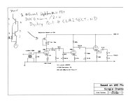
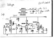
Ages ago I modified my WAD Phono II scratch build. Inspired by a Nick Gorham modification (attached), I added CCS on top of the first stage. I also put a CCS under the third stage CF (not documented here).
After a couple house moves, I lost all documentation of my current build. And I like it so much, I thought I’d document it here.
So I pulled the bottom off my phono stage to take a look at what I had done.
The CCS on top of the 1st stage is classic Gary Pimm, and I documented it on Nick’s modification attachment. I believe I set it for 0.9mA, but it looks to be 0.94mA as measured.
The first stage is the hard part as I understood the mod did change the RIAA equalization (3180+318).
I did the math back then (I think), but I document the ("unchanged") first stage output resistance here.
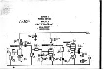
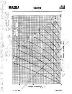
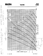
The WAD ECC83 operating point (schematic attached) is B+ = 250v, Anode load resistor is 100k, 150v on the plate, -1.1v with 1.2k (un-bypassed) on the cathode. See the load lines attached.
I calculated anode resistance as (332v-78v)/(3.5mA-0mA)=72.57k
Since it is not bypassed and u=100 and cathode resister = 1.2k, I get 72.57+[(100+1)*1.2]=194k
That in parallel with the anode load of 100k = 66k
With the CCS load, I used 1M resistance (Nick Gorham's suggestion) in parallel with 72.57k, giving 67.7k
So 66k vs 67.7k per my calculations. Close enough?
Referencing Morgan Jones I can’t prove out the rest of the equalization circuit (oh well). But I sure do like this mod.
I’m thinking one day to figure out how to put a CCS on top of the 2nd stage valve. (Allen Wright's approach - if it is not supposed to move, lock it down tight.)
I attached a copy of the voltages of my modified build too.
After a couple house moves, I lost all documentation of my current build. And I like it so much, I thought I’d document it here.
So I pulled the bottom off my phono stage to take a look at what I had done.
The CCS on top of the 1st stage is classic Gary Pimm, and I documented it on Nick’s modification attachment. I believe I set it for 0.9mA, but it looks to be 0.94mA as measured.
The first stage is the hard part as I understood the mod did change the RIAA equalization (3180+318).
I did the math back then (I think), but I document the ("unchanged") first stage output resistance here.
The WAD ECC83 operating point (schematic attached) is B+ = 250v, Anode load resistor is 100k, 150v on the plate, -1.1v with 1.2k (un-bypassed) on the cathode. See the load lines attached.
I calculated anode resistance as (332v-78v)/(3.5mA-0mA)=72.57k
Since it is not bypassed and u=100 and cathode resister = 1.2k, I get 72.57+[(100+1)*1.2]=194k
That in parallel with the anode load of 100k = 66k
With the CCS load, I used 1M resistance (Nick Gorham's suggestion) in parallel with 72.57k, giving 67.7k
So 66k vs 67.7k per my calculations. Close enough?
Referencing Morgan Jones I can’t prove out the rest of the equalization circuit (oh well). But I sure do like this mod.
I’m thinking one day to figure out how to put a CCS on top of the 2nd stage valve. (Allen Wright's approach - if it is not supposed to move, lock it down tight.)
I attached a copy of the voltages of my modified build too.
Attachments

Last edited:

The above circuit is drawn incorrectly and I can't edit the post. Here is the circuit I used (ala Gary Pimm)

I'd like to load the 2nd stage plate with a CCS too.
The second stage operating point is B+ = 250v, Anode load resistor is 330kk, 95v on the plate, -1v with 2.2k (un-bypassed) on the cathode. See attached.
I calculated anode resistance as (390v-50v)/(3.5mA-0mA)=97k
Since it is not bypassed and u=100 and cathode resister = 2.2k, I get 97+[(100+1)*2.2]=319k
That in parallel with the anode load of 330k = 162k
With the CCS load, I used 1M resistance (Nick Gorham's suggestion) in parallel with 97k, giving 88.4k
So 162k vs 88k per my calculations. So I need to add 73k more for r out to be the same?
Attachments
Recalculating the 75us time constant in the 2nd stage, I get:
75us/342k(r out of 162k + 180k resistor) =219pF with no consideration of Miller capacitance or strays.
The WAD circuit uses 220pF here.
In the WAD circuit, the cathode is not bypassed and I got gain of 68 (bypassed) and 47 (not bypassed) using 68/(1+((2.2/330)x68))=47
So wouldn't the Miller capacitance be 47 x 1.6 pF (C a-g)= 145pF
What am I missing? Wouldn't the cap be more in line with 220pF-145pF?