Hi all,
me and a friend are going to build ESL after building "normal" speakers for centuries.
So far we've read a lot about ESL's. The more we read, the more questions we have... I gues you know what I mean")
Anyway, we are going to build hybrid speakers, me i'm going to use a Ripol (since i am a big Open-Baffle fan) for the bass section, my buddy will use a closed box.
We decided to cross them around 200-250 Hz. If passive or active is not sure at the moment...
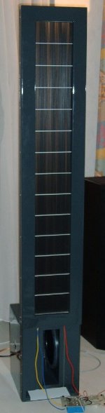
The panel size will be 285x900mm divided in 20-12-6-6-6-12-20 segments.
And here the questions start...
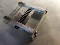
If we use aluminium profiles for the frame and also for the cross-braces and use duoble-sided tape 0,2mm for bonding the membrane to the frame, will there be enough insulation against the membrane and also the wires?
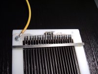
In the picture you can see that we tried two different sizes of ds-tape, one is 0,2 mm, the other one is 1.5mm thick. This was to check wether the braces will stick strong enough to the frame, unfortunately they do not. Next step will be to check wether glueing the braces with Sikaflex221 to the frame.
If we use rivets to fix the braces it is ok, but we lose the insulating effect of the frame material, this is a sandwich of aluminium and some plastic (here in Germany it is called Alucobond).
Don't mind the stator wires on the pictures, this was only to check how fast the glue is drying.
Another question concerns the distance from stator to membrane. Since the material we want to use for the frame was only available in 4mm and we want to keep things simple, the distance/gap between stator wires (outside of the insulation) is only 2mm instead of 3mm like described on the website of Steen Frank Jensen.
To be honest, to keep things simple we are going to copy his model since it is not that big.
We also like all the other stuff we have seen here in this forum but most these ESL's are too big.
Anyway we include some ideas from here in our building process...
So we are looking forward to your answers.
We are sorry for the chaos with the pictures... We couldn't find a way to delete the needless ones...
Best regards, Juergen and Dani
from Germany


me and a friend are going to build ESL after building "normal" speakers for centuries.
So far we've read a lot about ESL's. The more we read, the more questions we have... I gues you know what I mean
Anyway, we are going to build hybrid speakers, me i'm going to use a Ripol (since i am a big Open-Baffle fan) for the bass section, my buddy will use a closed box.
We decided to cross them around 200-250 Hz. If passive or active is not sure at the moment...
The panel size will be 285x900mm divided in 20-12-6-6-6-12-20 segments.
And here the questions start...
If we use aluminium profiles for the frame and also for the cross-braces and use duoble-sided tape 0,2mm for bonding the membrane to the frame, will there be enough insulation against the membrane and also the wires?
In the picture you can see that we tried two different sizes of ds-tape, one is 0,2 mm, the other one is 1.5mm thick. This was to check wether the braces will stick strong enough to the frame, unfortunately they do not. Next step will be to check wether glueing the braces with Sikaflex221 to the frame.
If we use rivets to fix the braces it is ok, but we lose the insulating effect of the frame material, this is a sandwich of aluminium and some plastic (here in Germany it is called Alucobond).
Don't mind the stator wires on the pictures, this was only to check how fast the glue is drying.
Another question concerns the distance from stator to membrane. Since the material we want to use for the frame was only available in 4mm and we want to keep things simple, the distance/gap between stator wires (outside of the insulation) is only 2mm instead of 3mm like described on the website of Steen Frank Jensen.
To be honest, to keep things simple we are going to copy his model since it is not that big.
We also like all the other stuff we have seen here in this forum but most these ESL's are too big.
Anyway we include some ideas from here in our building process...
So we are looking forward to your answers.
We are sorry for the chaos with the pictures... We couldn't find a way to delete the needless ones...
Best regards, Juergen and Dani
from Germany
A few suggestions:
I would use a non-conductive material for the horizontal wire supports. The insulation on the wires alone would not sufficiently isolate them from conduction into aluminum supports.
I'm a bit confused about your description of what the diaphragm-to-stator spacing (d/s) will be. Minimum spacing gives the highest acoustic output, and each doubling of the d/s decreases output by a factor of four. If your crossover frequency will be 250Hz, you can use as little as 1.5mm spacing to achieve the highest output. But if you double the d/s to 3mm, the output will decrease by 400%.
Also be aware that a Ripol exhibits a rather loud chamber resonance, and for your 12" Ripol, that resonance fall somewhere around 300Hz. I happen to have 12" Ripol subs, and their front chamber resonance is a loud peak at 299Hz.
You can mitigate the Ripol's chamber resonance with a notch filter or a parametric EQ, which you will have to do if you want it to play high enough to server as the mid bass woofer in your hybrid ESL.
An alternate approach would be to use a separate mid-bass woofer mounted on a open baffle below the ESL panel, and add the pair of Ripol subs crossed in at least one octave below their chamber resonance, using a steep filter slope. In this way you avoid exciting the Ripol's chamber resonance.
You may find some useful information on my website here: https://jazzman-esl-page.blogspot.com
Hello Charlie,
thanks for your immediate reply!
And also thank you for your very informative mail you sent me some weeks ago!
It very helpful to have some information at hand. But we also want to put a little of our own "inspiration" and ideas in our project.
We do not just want to stupidly copy something...
The problems with Ripols are well known, so this is not the "task" at the moment.
The idea to make the frame and the braces came from the website of Steen Frank Jensen.
I like this cool high-tech-look of the aluminium together with the black stator wires. Since there are no children in our households we don't cover the speakers.
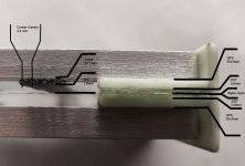
The spacing we want to do is shown in the picture. Charlie, the wire you suggested is way too expensive here in Europe and my colleagues that are working in our factory in Saline are more or less fully at capacity transporting stuff for all friends and colleagues here in Germany...
So we are going to use 0,5 mm² massive wire with an outside diameter of 2,0 mm.
Steen is using a d/s of 3mm along with 5700V. Since the material we got here is forcing us to a d/s of 2mm we are asking us what is going to happen.
Charlie, as you said the output will increase, this seems to be good. Do we have to change the supply voltage?
We also asked us to use an adjustable voltage supply like this one:
https://highvoltageshop.com/epages/...9ffc-4fd5c619abc4/Products/HVGEN_POS_10KV_var


thanks for your immediate reply!
And also thank you for your very informative mail you sent me some weeks ago!
It very helpful to have some information at hand. But we also want to put a little of our own "inspiration" and ideas in our project.
We do not just want to stupidly copy something...
The problems with Ripols are well known, so this is not the "task" at the moment.
The idea to make the frame and the braces came from the website of Steen Frank Jensen.
I like this cool high-tech-look of the aluminium together with the black stator wires. Since there are no children in our households we don't cover the speakers.
The spacing we want to do is shown in the picture. Charlie, the wire you suggested is way too expensive here in Europe and my colleagues that are working in our factory in Saline are more or less fully at capacity transporting stuff for all friends and colleagues here in Germany...
So we are going to use 0,5 mm² massive wire with an outside diameter of 2,0 mm.
Steen is using a d/s of 3mm along with 5700V. Since the material we got here is forcing us to a d/s of 2mm we are asking us what is going to happen.
Charlie, as you said the output will increase, this seems to be good. Do we have to change the supply voltage?
We also asked us to use an adjustable voltage supply like this one:
https://highvoltageshop.com/epages/...9ffc-4fd5c619abc4/Products/HVGEN_POS_10KV_var
I love Mr. Steen's excellent website and speaker design.
Mr. Steen defines the d/s as 3 mm, which is calculated by averaging the distances from the center of the copper wire to the diaphragm (3.2 mm) and from the edge of the copper wire to the diaphragm (2.825 mm). What is not clear to me is whether or not the "edge of the cu wire" includes the insulation (probably not).
An interesting side note:
When I was designing my first wire-stator speaker, I initially assumed that the d/s calculation should not include the PVC insulation because I assumed it was non-conductive. However, it was explained to me by other [well respected] builders on this form that PVC insulation is preferred for ESLs because it's a relatively poor insulator compared to most other insulation types, so it doesn't impede output very much, and in fact it actually conducts as the very high voltages used in ESLs.
I recall reading somewhere that the old Acoustic panels used tiny 24 gauge wire with massively thick 0.040" PVC insulation to prevent arcing, yet the thick PVC insulation had surprisingly little effect on output, and being essentially conductive at the voltage level used, was considered a mere extension of the wire conductor.
Accordingly; I use only PVC insulation, and I base my d/s calculation as the distance from the diaphragm to the edge of the insulation on the wire. In my speaker, the d/s is thus 0.063" (about 1.5 mm).
The consensus opinion considers the d/s as the primary design consideration, and the choice of wire size, wire spacing, and biasing voltage follows from the d/s. That is [for highest efficiency]; only PVC insulated wire should be used, it's O.D. (including insulation) should not exceed the d/s, and the spacing between wires (O.D. to O.D) should not exceed the d/s.
If your d/s will be 2mm, and your wire is 2mm O.D. and the edge-to-edge spacing between wires does not exceed 2mm, then efficiency should be less than optimal but still pretty good.
As for the biasing voltage;
It should not exceed 1/2 the breakdown voltage of the d/s air gap. The breakdown voltage of dry air is about 100 volts/mil, and 2mm is about 0.079, giving 7,900 breakdown voltage, and half of that sets your max bias at 3,950 volts.
The bias supply needs only a very small amperage so any adjustable bias supply that can supply 4kv should suffice.
My speaker uses 1.5 mm d/s and (2) 230v/6v toroidal transformers giving about 76:1 ratio, which is sufficient. Whereas Mr. Steen's speaker uses 3mm d/s and probably needs (4) transformers / 150:1 ratio to offset the efficiency loss and provide good output.
I'm thinking your speaker could get by with only (2) of the 230V/6V transformers. The downside would be somewhat lower efficiency because your d/s is a bit more than optimal, but the upside would be lower cost, an easier load on your amp, and significantly better treble response. Just a thought...
Last edited:
If we use aluminium profiles for the frame and also for the cross-braces and use duoble-sided tape 0,2mm for bonding the membrane to the frame, will there be enough insulation against the membrane and also the wires?
Not entirely clear what you mean. If the frame is really conductive, I do not see how to make this work. If the coating is applied to the entire membrame surface, on the coated side you have just 0.2mm air between the coating and the frame at the edge of the frame. On the other side 0,2mm air + 3um mylar. That will not do of course.
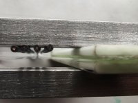
A possible way around this is to apply the coating only on the center of the membrame, keeping about 1 cm of clearance from the frame all around. I use this method on my Audiostatics and it works very well to keep leakage to a minimum. Around the perimeter I apply a small strip of highly conductive paint (graphite paint), this helps to charge up quickly and maintain an even charge all over the membrame. At only one point I extend this paint to the frame, at which point I apply a strip of copper foil to make the HV connection (se left bottom side in the picture).
But in my case the frame is non-conductive so it is safe to bring the HV potential to the frame at one point for the connection without the risk of leaking. If the frame is conductive, I would not know how to make a durable HV connection to the membrame that will have sufficient isolation value to the frame.
The panel size will be 285x900mm ... We decided to cross them around 200-250 Hz.... the distance/gap between stator wires (outside of the insulation) is only 2mm
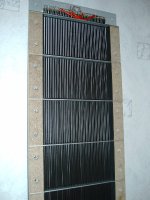
A general rule is that the ratio between panel width and DS should be 70 at most (with high membrame tension up to 100 is possible, but better stay on the safe side for a first build). Otherwise the max achievable membrame tension will not be sufficient to prevent the membrame from collapsing into one of the stators when the HV bias is applied. That means 4 mm as a minimal DS, 3mm if you tension the membrame to the max. With smaller DS, you will need to support the membrame in between, Audiostatic used the silicone dots you see in the picture for this. Although they use a ratio of 70 as well. The dots also help to dampen the resonance, making the peak wider and lower.
For a panel that is crossed at 200-250 Hz, a DS of 1,5-2 mm is sufficient. I would aim for 2 mm buth then you will need to add silicone dots or other means of supporting the membrame, reducing it's efffective width.
Keep in mind a DS of 3 mm or more that is needed for a panel of 285 mm will require very high drive voltages, and a stepup ratio in the transformer of 1:100 at least. This is making things much more difficult from a tranformer design point of view and more or less rules out the use of cheap 6/230V toroids or tube output transformers as stepup. You will need a highly dedicated stepup transformer to get decent performance at 1:100 or more. For a hybrid panel that will be crossed over at 200 Hz or higher, there is really no need for such a wide membrame so I would suggest to reduce the membrame widt to about 20 cm. That allow the DS to be reduced to 2 mm.
It's a good idea to have a look at commercial panels. The Audiostatic ES200 in the picture above uses a 20x100 cm membrame with a DS of 2.8mm. Stepup is 1:150, incresing to as much as 1:300 at low frequencies because of the mirror drive system. These panels will play fullrange down to 35-40Hz, albeit at limited SPL. Crossed over to a sub at 100 Hz or higher they can play earshattering loud, so really no need to go much bigger on a hybrid system.
One final remark: the use of double sided tape for attaching the membrame to the frame looks attractive, but my personal experiences is that tape will always allow the membrame to creep over time causing it to loose tension. Even the very expensive ones from reputable brands. I therefore prefer to glue the membrame (using 2k PU).
Last edited:
So far i thank you all for all the very informative replies.
One thing i forgot to mention is, that we will support/dampen the membrane underneath the crossbraces which have a distance of 100 mm.
Tomorrow i will start to a one week holliday in Cyprus thus i will have a lot of time to think about the usefull information i got from you.
For sure we will have to change some parts, parameters and also calculations, but that's the way it should be.
Here in Germany we have a saying: "No one is born a master" or "No master has yet fallen from heaven".
For us it is already a real interresting journey...
I typically used 3M polyester high dielectric strength tapes for applications like this. Kapton is another option.I would not know how to make a durable HV connection to the membrame that will have sufficient isolation value to the frame.
I often used it on the edges of powder coated perforated metal stators, since it was hard to cover the sharp points adequately without super thick coatings. And if your bias connection is essentially sitting on top of that, it's that much harder on the insulation.
Of course it's better if you don't have to use insulation to deal with a situation like this, but a couple layers of the right kind of tape can help a lot.
Hi,
as most of the others already noted, might the Alucupond frame be the cause for issues.
I´m not sure why you wanted to use this material in first place?
Did You want to omit with a mounting frame alltogether?
This would of course require a mechanically stiffness/stability that a typical ladder-style frame couldn´t supply for ... though I doubt, that Alucubond would suffice in this regrad also.
Since You almost inevitably have to built the panel into a mounting frame, this frame provides for the rigidity and can and will dominate the optical appearance.
As Acoustat panels show, the ´functional´ panel frame can be made quite ugly looking, but from appropriate-to-the-application materials.
When I started building ESLs I copied alot from Acoustat designs, including the aluminum brackets.
It worked without issues, apart from some accumulation of charge that every now and then tickled You when touching it.
For my first panels I used 5mm thick PVC for the vertical ´rails´ and 2x10mm resp. 10x10mm aluminium brackets (hollow instead of massive, available at every DIY-market) and 5x5mm tinned steel (Mini-ESL 80x15cm).
Worked flawlessly apart from the reported tickle sometimes.
As wire I used off-the-shelf H07VU (OD2.65mm) or H05VU, PVC insulated common household wire, sourceable from almost everywhere at lowest cost (the cost for my first larger panel pair mounted up to 78.-DM wo. electronics, probabely 25€ nowadays)
The resultant air gap was 2.35mm (5-2.65mm) which allowed the panel to play down to ~100Hz.
Nowadays I´d choose a smaller gap of 1.5mm or less ... so, 4mm PVC spacers and H07VU wire are fine (as in Mini-ESL) for panels playing from 100-150Hz on up.
In my bowed punched metal stators I use 1.0/1.1mm air gap for >170Hz (btw. those panels offer efficiencies way above 90dB@4m@1W@1700V_bias)
Same as You .... just two decades earlier ... I designed a mating Ripole sub (ESEL03).
While it was certainly an improvement against other woofers, it never really played to my full confidence ... in part as it was quite limited in maximum SPL.
This changed ... besides some other major sonic improvements ... when I mated a dipolar woofer tower next to the panels.
Attached are some pics and PDFs .... just digest it with a pinch of salt ... some of it may be outdated in the meantime
jauu
Calvin
as most of the others already noted, might the Alucupond frame be the cause for issues.
I´m not sure why you wanted to use this material in first place?
Did You want to omit with a mounting frame alltogether?
This would of course require a mechanically stiffness/stability that a typical ladder-style frame couldn´t supply for ... though I doubt, that Alucubond would suffice in this regrad also.
Since You almost inevitably have to built the panel into a mounting frame, this frame provides for the rigidity and can and will dominate the optical appearance.
As Acoustat panels show, the ´functional´ panel frame can be made quite ugly looking, but from appropriate-to-the-application materials.
When I started building ESLs I copied alot from Acoustat designs, including the aluminum brackets.
It worked without issues, apart from some accumulation of charge that every now and then tickled You when touching it.
For my first panels I used 5mm thick PVC for the vertical ´rails´ and 2x10mm resp. 10x10mm aluminium brackets (hollow instead of massive, available at every DIY-market) and 5x5mm tinned steel (Mini-ESL 80x15cm).
Worked flawlessly apart from the reported tickle sometimes.
As wire I used off-the-shelf H07VU (OD2.65mm) or H05VU, PVC insulated common household wire, sourceable from almost everywhere at lowest cost (the cost for my first larger panel pair mounted up to 78.-DM wo. electronics, probabely 25€ nowadays)
The resultant air gap was 2.35mm (5-2.65mm) which allowed the panel to play down to ~100Hz.
Nowadays I´d choose a smaller gap of 1.5mm or less ... so, 4mm PVC spacers and H07VU wire are fine (as in Mini-ESL) for panels playing from 100-150Hz on up.
In my bowed punched metal stators I use 1.0/1.1mm air gap for >170Hz (btw. those panels offer efficiencies way above 90dB@4m@1W@1700V_bias)
Same as You .... just two decades earlier
... I designed a mating Ripole sub (ESEL03).While it was certainly an improvement against other woofers, it never really played to my full confidence ... in part as it was quite limited in maximum SPL.
This changed ... besides some other major sonic improvements ... when I mated a dipolar woofer tower next to the panels.
Attached are some pics and PDFs .... just digest it with a pinch of salt ... some of it may be outdated in the meantime
jauu
Calvin
Attachments
Hi all,
it's been a long time since my last post, i know and i am sorry for that.
A lot of things happened in the meanwhile, also to our construction...
I was working in the UK and due to some customs clearance problems we had to finish our work and fly back to Germany, where my colleaugue and I both got sick for 2 weeks. Then we went back for another 2 weeks which we had to extend due to the strikes at some german airports.....
But, i had enough time to overthink our plans.
Keeping all of your information plus Sanders Cookbook informations in mind we were doing some new constructions plans.
The new panel size will be 1200x208 mm. We will cross it at around 400-500 Hz. Below we use some woofer (in my case Open Baffle plus maybe a Ripol-Subwoofer below 70Hz)
D/S will be 1.8mm, which is given by the size of the spacers plus the DS-Tape (3mm + 0.8 mm) minus the outside diamter of the wires (2mm).
Our new frame wil be made of GFK (30x3mm) plus the already existing aluminium braces.
According to all gathered information we calculated the following:
For D/S 1.8mm we should have an audio voltage of 7 kV (according to Sanders who says 390V/0,1mmDS)
To me this seems to be very high, isn't it?
In that case we would need at least 5 toroids to get a ratio of 190:1
The bias voltage should be 3500V (195V/0.1mmDS)
The spacing of the braces will be 100mm, underneath we put a kind of cellular rubber tape with a thickness of 4mm.
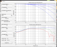
Attached you can find some fotos of a small look&feel modell i made today.
To make the film better visible i used some gift wrapping film of my girlfriends shop
Also i attached a screenshot of the simulation.
What do you think about our new design? Do you have any suggestions for improvement?
Greetings from Germany,
Jürgen and Danilo
it's been a long time since my last post, i know and i am sorry for that.
A lot of things happened in the meanwhile, also to our construction...
I was working in the UK and due to some customs clearance problems we had to finish our work and fly back to Germany, where my colleaugue and I both got sick for 2 weeks. Then we went back for another 2 weeks which we had to extend due to the strikes at some german airports.....
But, i had enough time to overthink our plans.
Keeping all of your information plus Sanders Cookbook informations in mind we were doing some new constructions plans.
The new panel size will be 1200x208 mm. We will cross it at around 400-500 Hz. Below we use some woofer (in my case Open Baffle plus maybe a Ripol-Subwoofer below 70Hz)
D/S will be 1.8mm, which is given by the size of the spacers plus the DS-Tape (3mm + 0.8 mm) minus the outside diamter of the wires (2mm).
Our new frame wil be made of GFK (30x3mm) plus the already existing aluminium braces.
According to all gathered information we calculated the following:
For D/S 1.8mm we should have an audio voltage of 7 kV (according to Sanders who says 390V/0,1mmDS)
To me this seems to be very high, isn't it?
In that case we would need at least 5 toroids to get a ratio of 190:1
The bias voltage should be 3500V (195V/0.1mmDS)
The spacing of the braces will be 100mm, underneath we put a kind of cellular rubber tape with a thickness of 4mm.
Attached you can find some fotos of a small look&feel modell i made today.
To make the film better visible i used some gift wrapping film of my girlfriends shop
Also i attached a screenshot of the simulation.
What do you think about our new design? Do you have any suggestions for improvement?
Greetings from Germany,
Jürgen and Danilo
Attachments
Last edited:
Consider a much lower crossover frequency. With a crossover frequency in the 400-500Hz region you will never get a good integration between woofer and ESL. For open baffle or ripole you will need something in the 12 inch range as a woofer. You'll be struggling to get decent performance from that up to 150-200Hz, especially in a dipole H or U frame or ripole enclosure. 400 or 500Hz is almost impossible without severe colouration, breakup and resonance issues that will ruin the overall performance.
An ESL panel of the planned dimensions will easily play down to 100-150Hz, so there is no reason either for choosing such a high xo. So I would strongly recommend to choose your crossover point well below 200Hz.
With a 1.8 mm panel ds, a 1:100 transformer with a amplifier of 100W in 8 ohms will probably give you plenty of drive voltage for normal listening spl's.
Ok, so we will cross them lower. Thats not the point.
What i wonder is, that there is such a big difference between what Sanders says and what many of ESL-builders say...
As said, if i take Sanders in account, I should have an audio voltage of 7 kV at 1.8mm DS. When chosing 230V/2x6V toroids (38:1) i'll get around 1440V out of them when powered by my amps, that deliver around 38V (160W RMS @ 8Ohm). This means i have to use 5 toroids to reach that voltage.
So, there are a lot of different statments out there. Ok, i know this cookbook is a little bit older, thus maybe, in some points, outdated...
Anyway, OB is not what i'm interrested in right now. What we want to know is just, if this mew design will be plaing well.
Maybe I was inattentive to read messages from colleagues, but I did not see what will be the resistance of the membrane coating, it is 300 kOhm or 1 Mohm or 1 Gohm, and it depends on this bias voltage (bias) and sensitivity of the speaker, and it is even more important than the gap membrane-stator?
Never use double-sided tape when gluing the diaphragm, it will eventually lose tension and you will have to redo it again.Even among glues it is not easy to find a non-flowing glue, I have been using glue "desmokol" for 12 years.Even since those times there are very large speakers and work perfectly.
If your stators are flat, not cylindrical as in Martin Logan, then you should make the gap diaphragm-stator at least 2mm.Because in this case the diaphragms will work in piston mode and the amplitude of oscillation can reach a decent distance at high loads.
Also in this case the frequency range can be reduced to 100Hz.
Part of the issue is whether you are talking about peak-to-peak voltage or RMS. For 1.8 mm diaphragm-to-stator spacing, my calculations suggest 3523 V bias, and 7045 V peak-to-peak of audio signal, which can be achieved with 1:70 step up and 160 watts of amplifier power (at 8 ohms).38V (160W RMS @ 8Ohm
I would not typically run the step-up ratio that low for that spacing though. You want the largest turns ratio you can get while maintaining the frequency range you need, unless you want to use all of a powerful amplifier's output or if you just don't care about anything other than quiet playback. Consider the Quad ESL-63 and its derivatives: spacing is 2.5 mm, and step up is 1:245. Some of the old Janszen panels were 0.28 mm spacing with 1:72 step up.
The other thing to keep in mind with the Sanders designs is the panel sizes were typically pretty large and not segmented. That's not the way most people approach electrostatics these days.
Last edited:
The d-s spacing (i.e. membrane excursion) not determinated the piston-like mode. Do you know any physical law, which can determinate the movement-mode's exchange when the membrane excursion increase?If your stators are flat, not cylindrical as in Martin Logan, then you should make the gap diaphragm-stator at least 2mm.Because in this case the diaphragms will work in piston mode and the amplitude of oscillation can reach a decent distance at high loads.
In a semi-cylindrical stator of Martin Logan type divided into small sections it is possible to reduce the diaphragm-stator gap, because there is practically no piston mode of diaphragm movement, but in a straight stator and diaphragm the piston mode works in full force, therefore the diaphragm-stator distance should be doubled, otherwise in a peak signal the diaphragm can touch the stator and if the insulation is insufficient, the diaphragm can burn out.
This is the whole "physical law".
This is the whole "physical law".
This isn't physical law, only intuitive, but false subjective opinion. The ML and the straight ESL work non-pistonic mode, only the ML has lower membrane compliance and inhomogenous driving force, bacause its geometrical structure complex. The straight ESLs has near homogenous driving force, but the acoustical load non homogenic, and the membrane suspension functioning like a drumskin, not as a piston (i.e. membrane perimeter stiffer).
Adnexum: the straight membrane at relative high frequency tends piston-like behaviour, because the acoustical load and electrostatic driving force much higher than elastic force. It's self-understanding: at the identical SPL, but much higher frequency causes smaller excursion. At this circumstances will be winners the homogenous effect forces (but can appears structural resonances)
Of course, it should not be considered literally as a piston stroke of a motorcycle cylinder, but only conditionally. Also do not forget that the "piston stroke" depends on the tension of the diaphragm, more tension - less stroke.
If there was no piston mode in the stretched diaphragm at all, there would be no low frequencies emitted by the diaphragm, for example 30Hz.
If there was no piston mode in the stretched diaphragm at all, there would be no low frequencies emitted by the diaphragm, for example 30Hz.
The thing is that "structural resonances" occur on a plane (membrane) which is activated in one or more places, but the value of electrostatic is that it is activated by a whole, continuous electrostatic field, there are no areas where the activation is more or less.Thus super light membrane is damped by the mass of air, because the mass of air is greater than the mass of the adjacent membrane.That is why electrostatic has such a small distortion of sound.At this circumstances will be winners the homogenous effect forces (but can appears structural resonances)
This isn't true... The drumskin mode can produce a lot of low-freq. output, but smaller, than at pistonic mode.If there was no piston mode in the stretched diaphragm at all, there would be no low frequencies emitted by the diaphragm, for example 30Hz.
- Home
- Loudspeakers
- Planars & Exotics
- ESL Newbie questions...