Good day, Gentlemen.
I am totally not a tube guy, but old pal desperately asked to overlook his Japanese domestic market ATM-2, which got issues. Among some simple-solving things like no voltage at the front end filaments, there is a thing which made me stumble: ATM-2 has indicator to set up bias manually and the circuit with indicator resistors was totally cut-off (modding, he-he). Now I am trying to understand how to measure bias at KT88. I studied some old posts here and found schematic (hand-drawing) which is very close to what I see on my table (attached), apart that there's EL34 instead of KT88 (no big difference). Figured that KT88 bias shall be around 30-50ma per tube. But what I see there is - no either anode or cathode resistor. Both cathodes are directly on ground, anodes directly to the trafo. Do I need to solder-in 10 ohm resistors to cathodes, set bias and then to remove them? I am not plaiing to re-instaill indicator circuit. What I can measure is about 480V anode-to-cathode and 0,3V between anodes of KT88 pair. Please help.
I am totally not a tube guy, but old pal desperately asked to overlook his Japanese domestic market ATM-2, which got issues. Among some simple-solving things like no voltage at the front end filaments, there is a thing which made me stumble: ATM-2 has indicator to set up bias manually and the circuit with indicator resistors was totally cut-off (modding, he-he). Now I am trying to understand how to measure bias at KT88. I studied some old posts here and found schematic (hand-drawing) which is very close to what I see on my table (attached), apart that there's EL34 instead of KT88 (no big difference). Figured that KT88 bias shall be around 30-50ma per tube. But what I see there is - no either anode or cathode resistor. Both cathodes are directly on ground, anodes directly to the trafo. Do I need to solder-in 10 ohm resistors to cathodes, set bias and then to remove them? I am not plaiing to re-instaill indicator circuit. What I can measure is about 480V anode-to-cathode and 0,3V between anodes of KT88 pair. Please help.
Attachments
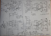
If this were my amplifier I would solder in 1 watt 10 ohm resistors in the cathode circuit to ground and leave them in. Ten ohms provide an easy way to measure tube current and is low enough that it will not affect operation or sound quality. Use at least 5% resistors or better. (Again if mine I would install pin jacks on chassis top to measure from without working from bottom.) 50mA equals 0.5V across 10 ohms.

Just add the 10 ohm resistors and leave them there, they are not going to affect the output tube operation. Plenty of professional amplifiers using fixed bias do that.
...
Ps just saw the previous post, sorry.
...
Ps just saw the previous post, sorry.