Metronome for Alpair 10.3m and 12p

Hello Gents,

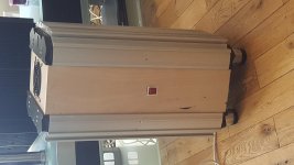
I would like to build a metronome style cabinet for Alpair 10.3m and 12p ( I already have a pair of each). After much digging around on this forum and other places, I haven't found specific dimensions for alpair drivers. I have been to frugal horn's metronome page and checked out the table, but I don't understand how to calculate specific dimensions for the alpairs. Is it as simple as matching similar size driver for example: build the cabinet for Fostex 207 and mount the alpair 12p or are there enough differences in drivers that the dimensions of the cabinet need to be specifically matched to each driver? If the later, how do I calculate this (bear in mind my math knowledge is about algebra 2 level with a touch of geometry and no trig and 15 years rusty).

I've already built a super pensil 12, and will probably do a quick and dirty sp 10, and maybe a frugal horn too for comparison. If the sound of either of those is significantly better than the metronome, I may stick with the sp/fh, but the WAF of the metronome is huge. To quote the wife when I showed her a bunch of pics of some gorgeous pensil style cabs and a simple metronome: "Those just look like speakers. The metronome looks like a nice piece of furniture."

How to reduce gain in integrated tube amp

I have an Audio Innovations s300 that I really like.
However, the gain is too high using a 2V line input. I just move the pot from the intial 7 to 8 o'clock positon and it's already too loud.
Besides using resistors before the volume knob to attenuate, is there a better way to reduce the gain?
Please see the attached schematics of the amp and preamp section.
It'a pp ecl86 with no feedback. I hope those familiar with tube amps could provide some advice. Thank you.

Attachments

  • ai300pre-1.gif
    ai300pre-1.gif
    16.1 KB · Views: 544
  • 300mk12.jpg
    300mk12.jpg
    193.4 KB · Views: 595

FS: LM555 time delays for tube amps and assorted surplus boards.

I ordered about 20 Pcb's for a LM555 based turn on delay, more then i ever need.

So i am selling the PCB's with a BOM and Schematic included. Or alternatively built and tested boards.


Function

The boards can be powered from 6.3VAC, once 6.3VAC is applied the relay will close in about 30-40seconds (trim-able with an on board trim-pot)


There is a footprint for a second relay, So you can switch dual mono supplies with this boards, i can supply a second relay.


The relay will switch 300VDC 440VAC and is rated for 15A.


The boards measure 49x100mm and have M3 mounting holes on 40x90mm
Connections are made through industry standard 6.3mm Fastons.


Attached you will find a schematic of the board.


Assembled and tested boards: €15. and a single PCB for €2.50


Shipping: EU only, for international DIY'ers you can ask me for the Gerbers. and i will send them to you for €1

Attachments

  • photo_2019-09-21_17-36-47.jpg
    photo_2019-09-21_17-36-47.jpg
    144.2 KB · Views: 457
  • photo_2019-09-21_17-37-08.jpg
    photo_2019-09-21_17-37-08.jpg
    132.8 KB · Views: 464
  • schema.png
    schema.png
    25.7 KB · Views: 459

back to back transformers grounding

Hello,


I'm new on this forum. I'm not an expert. I like tubes and most of my builds are simple SE tube amp. How would you ground the attached schematic ? I've seen many different layouts online. Would you add an artificial CT at T2 primary ? Should I ground the filaments 24V secondary or keep it floating ?


Tubes are in series (12A5, 6SF5, drop voltage resistor), full wave rectifier, 3-prong plug


Thanks in advance
Pat

Attachments

  • Clipboard01.png
    Clipboard01.png
    20 KB · Views: 151

Are there any rules on capacitor lead pitch please?

I'm following a set of instructions to upgrade caps in a preamp.
The electrolytics I have sourced have a 2mm lead pitch, but the space on the board is a larger 10mm pitch.
Is it generally OK to bend leads 'flat' to the PCB...or can the (small) electrolytic 'fly' above the surface using a more gentle bend??


Should the replacement component pitch be closer to the available PCB pitch is what I'm asking I suppose! 🙂

Understanding Isolation Transformers

Hi, First time posting here.

I bought a bunch of All American Five radios with the idea of gutting them, essentially just keeping the vintage shell and the chassis. And then building a small 1 or 2 tube amp with bluetooth input. Basically a vintag-y tabletop bluetooth player for gifts. (Yes I realize that it would be cheaper, easier, and probably sound better if I bought a bunch of Chinese class-d amp boards, but my friends all know I build tube guitar amps, and I can't go around giving them all guitar amps!). I don't need more than 170v so I can use an admittedly-inexpensive 120/120 transformer and a solid state rectifier, but then I got thinking....

First of all, I totally get why the AA5 design was a safety disaster, and I get why iso transformers protect the against the situation where the presumed-neutral wire shares a common ground with the circuit (because it may in fact be hot). But...

If the picture below represents my design without a transformer, what is the advantage of putting a transformer between A-B? I'm trying to understand the scenario where the transformerless design is less safe. Are there other considerations (noise, etc).

It seems like heresy to ask these questions. I got my head taken off over at a guitar amp forum just for asking, and never got an answer that I could understand. I'm happy to do it "just because" (which was the answer I eventually got), but I really would like to understand.

btw, someone will ask "what about the heaters?. I have no interest in stepping wall voltage down to 6.3v with resistors, zeners, mosfets, or capacitors - too many issues there - so I will get small 120/6.3v transformers for that. I'm just wondering if I can keep my "iron" to one inexpensive transformer.

Thanks. Be nice.

Attachments

  • pwr1.jpg
    pwr1.jpg
    351.2 KB · Views: 457

American tubes

Sale:
6B5 Sylvania - 2 pc. for $16 ea.
6C4 - 3 pcs. for $8 ea.
6F6 RCA - 1 pc. for $8
6F6 Ken-Rad - 1 pc. for $8
6F7 Ken-Rad - 1 pc. for $8
CRC-6J5 RCA - 1 pc. for $8
6L6 RCA - 1 pc. for $16
6L6G RCA - 1 pc. for $22
6SN7GTB GE - 1 pc. for $22
CRC-6V6 RCA - 1 pc. for $8
25L6GT Sylvania - 1 pc. for $16
42 Purotron - 1 pc. for $22
42 Radiotron - 1 pc. for $22
80 Ken-Rad - 1 pc. for $22

contact cleaner

For cleaning mechanical switches I normally use KONTAKT 60, followed by a flush of KONTAKT WL.
Normally, this works O.K.
Recently, after some time, the treated switches again had contact problems.
Then I used WD40, and the switches seem to stay O.K., also after several days.
Is WD40 really a good contact cleaner?
I had succes with WD40 with a Onkyo and a Kenwood amplifier.

PD1850 Vs Void 1000 Vs ????

Hi,

I'm looking for some something to fill my 18" Mogale Super Scooper but with coronavirus and shipping/production from the EU times are tough. The PD1850 and Void 1000 are both made in the same place and I would like to finish my project during this down time.

Can anyone suggest a worthy replacement that is available in the US? Even better would be in or near NYC. Inventory from US speaker could suffice if they have the part.

Thanks!

FS: Bartola assembled Gyrator for DHT

SOLD
Up for sale are two complete assembled Gyrator boards from Bartola.
They are ideal for low current DHTs like 26 and 01A but other tubes also can be used but please consult Ale from Bartola valves!

Step-7-C1-option-2.jpg


All the parts used are high quality! I will include also 0.1uF obbligato 630V film caps! I used matched 2sk170BL transistors also!

Price: 35 USD / assembled board

For actual pictures of the boards please send me your e-mail.

I am shipping worldwide!

Rockville amp output inductors damage

I worked on a Rockville amp yesterday and found that both of the output inductors were cooked. I haven’t found any other damaged components in the amp. It looks like a very new amp, less than a year old.

I know that vibration damage is a major factor for these inductors to fail, but I’m not sure that vibration caused this failure. What else could cause the output inductors to cook.

David

Attachments

  • 24B28F34-E9FB-46B2-B466-EF8D890C885A.jpg
    24B28F34-E9FB-46B2-B466-EF8D890C885A.jpg
    1,014.2 KB · Views: 175
  • D8B7D9B9-1438-4433-B051-13B93861408B.jpg
    D8B7D9B9-1438-4433-B051-13B93861408B.jpg
    985.6 KB · Views: 151
  • 2B39C86F-5221-4949-AB6F-4DD43D33C437.jpg
    2B39C86F-5221-4949-AB6F-4DD43D33C437.jpg
    686.6 KB · Views: 162

Taramps HD8k low volume output

I have a Taramps HD 8000 on the bench that has significant ringing on one side of the output transistors, and uneven voltage on the speaker terminals. I’m thinking the the higher voltage present on the positive terminal is be induced by the ringing. I tried wiggling the output inductors for both sides and it didn’t affect anything.

I’m getting 176 volts rail on both sides, but I’m suppose to get half rail voltage at the speaker terminals. I get 88 volts on the negative terminal and 96 volts on the positive side. I see these same voltages at the output mosfets as well.

I am attaching screen shots of the drives on each side.
Scope settings are 5v 10us probe is set to x10.

Has anyone seen this before? Suggestions?

David.

Attachments

  • 2BB379EA-8B56-42FF-80AE-F659179919A0.jpeg
    2BB379EA-8B56-42FF-80AE-F659179919A0.jpeg
    281.7 KB · Views: 117
  • C49F89E2-13FC-4C42-B5E2-CFE87E1CAB08.jpeg
    C49F89E2-13FC-4C42-B5E2-CFE87E1CAB08.jpeg
    276.3 KB · Views: 118

Heathkit transformer replacement...

Hello all, I have an old pair of heath amps, usually I'd be on here blathering on about issues with the Power amp, an AA-121 (EL-34 PP stereo)- but now I am going to blather on about an issue with the matched preamp.

The Preamp is an AA-141A unit and what has happened is that I lost plate voltage the other night running the tuner quietly.

After poking around with the meter, I have determined that the B+ tap on the power transformer has gone open. Must've popped the winding. It still powers up and I have filament heat and a pilot light on the front, so I know that at least the 6 volt taps are still working, but that doesn't amount to a **** hole in a snow bank without voltage on the plates.

Now, the heathkit part number on the top of the xfmr is 54-71, and after googling around I have come up with zilch, so I may have to order an aftermarket unit.

The question is, what the hell am I looking for. I've never had to buy a transformer before.

With a designed input voltage of 117VAC I have 2 6.3V taps for the filaments and a 238V tap after a couple of Selenium diodes for the B+ supply. I never had a meter on the winding while it was working, so I dont know what the actual voltage on the winding was. These numbers are "what I should have" according to the schematics.

What does having a transformer re-wound usually cost?

Grounding Funkyness in SS guitar amp

Hello,


I picked up this solid state Marshall Mosfet 100 guitar amp for $5.


It obviously didn't work when I brought it home. It would make sound and seemed to work until I inch the master volume up past three. Then it just squeals and makes robot noises.


After messing around with it, I discovered that If I put a jumper between the circuit ground and the chassis, it would work perfectly. No squealing, no robot noises, just guitar noises.


I checked the voltages across the filter caps, and when the circuit ground is disconnected from the chassis, they go wild. They overshoot the rated values, and are crazy volatile. When the ground is connected the chassis, they are nice and steady. It does use a bipolar power supply. My current hypothesis is that the circuit ground has no reference to hold it at a steady 0 V, so it goes all wild until connected to earth ground? I don't know enough to know anything for certain.


I'm glad I figured this out, but I have no idea why this fixes it. I also have no idea what had been done to it before I got my hands on it.


If anybody understands why this happens, and why connecting the circuit ground to the chassis fixes it, please let me know. I want to learn.

Unknown HV regulated power supply(German)

Hi guys,
Does anyone recognize this device?
Regulated voltage stabilizer with E130L pass device(ef83,ecc283 plus some OA2..)
Unfortunately,there is no labeled anywhere.But looks like professional,with some germans inscriptions.
I appreciate schematic,tech. manual or any info.
Many thanks,

Attachments

  • s-l1600 (1).jpg
    s-l1600 (1).jpg
    470.2 KB · Views: 323
  • s-l1600 (9).jpg
    s-l1600 (9).jpg
    343.5 KB · Views: 308

New Guy From (Almost) The Middle of Nowhere

Hi Folks;

New to audio forums, but not forums as a species. Have finally returned to my (audio) roots. Stuck in the '70's and '80's, so don't beat me up too bad. Seem to have an affinity for JVC and Technics, but am constantly on the lookout for anything kinda cool. Of course, being car-poor, it squeezes the budget. I have waaaay too many cars. But, I digress.

Anyway, happy to be here and will try really hard to not make a fool out of myself. Remember, newby on the premesis...

Thanks to all,

Mike

Dedicated tweeter amp & crossover

Hi diyaudio world. i need help & guidance.
i want to make a dedicated stereo tweeter amplifier
& active crossovers. As you have guessed; i have very little knowledge about active crossovers, related equation & math.

i want to use tweeters with my sealed woofers
(not sub woofer). i'm currently using lm3886 stereo with those woofers without any active crossover.
The frequency response of my woofers is good upto 2-3Khz approx & that is just my guess because the manufacturer didn't provide much information about those woofers. Actually i don't need high level accuracy, just good music 🙂

For tweeter amps i'll use chipamp like 1875 or maybe tda2050 but i need help to make active crossovers for
tweeters. A good schematic diagram & some advice
enough for me.
as much as i know-
1)Sealed box exhibit a shallow roll-off of about 12dB/octave compared to bass reflex with 24dB/octave roll-off slopes.
2) sensitivity of tweeter & woofer should be same or at least very close.

i have some ne5532 & tl072 op-amps in my hand & i want to use them. i hope I've been able to explain my problem 🙂

wood with dissimilar expansion rate techniques ?

I guess Im stubborn, chose a material with an unknown expansion rate. 3/4" Bamboo board. One site says it has alot of movement, another says its pretty stable.

As this is only the outside of the enclosure, I planned on lining the interior with another layer of 3/4" ply or 1/2" MDF.

I know if I simply glue the interior panel to the bamboo, the boo will eventually split from shrinkage. Even if it is stable, I doubt it is as stable as MDF or plywood.

My plan is to run a bead of adhesive down the center of the widest panel on the inside) (its the side panels and 1'3" wide) and leave outer edges of bamboo to more or less slide against the interior panel (that will be cut 1/4" narrower) I was thinking of may be a few dabs of silicone in the corners between the 2 and or may be adding a slot in the interior material and snugging up a screw with washer so there could be a little movement.

Beyond that, Im not 100% sure, has anyone here worked with dissimilar materials and accounted for movement ? Curious how you did it !

FS - Various Audio Tubes (12AX7, 6L6, 6DJ8, etc)

Hello,

I have the following audio tubes for sale. More will be added from time to time. If you have any questions or would like a shipping estimate please feel free to PM me. Thank you.

For sale is a pair of Amperex 6DJ8 ECC88 vacuum tubes. $35 plus shipping. Both tubes were produced by Philips in their Heerlen, Holland plant and these pair of tubes have the code sequences of GAO delta9H3 and GAE delta2G4. Both tubes have been tested for shorts, grid leakage and emission on a restored and calibrated Sencore TC-142 tube tester. The results are as follows:

Shorts: PASS
Grid Leakage: PASS
Emission:
Tube 1:
Triode 1: 101%
Triode 2: 102%

Tube 2:
Triode 1: 101%
Triode 2: 102%

In addition these tubes have had a life test performed on it which entails reducing the filament voltage of the tube by one step and noting any significant reduction in emission performance. These tubes performed very well in this regard.

attachment.php


For sale is a pair of Tung Sol 6V6GT vacuum tubes. $35 plus shipping. These tubes feature brown bases as well as smoked glass. They are in very nice shape save for a minor crack in both bases of the tubes. These can be seen in the first and second photo. These do not seem to affect the structural integrity of the tube. These tubes have been tested for shorts, grid leakage and emission on a restored and calibrated Sencore TC-142 tube tester. The results are as follows:

Shorts: PASS
Grid Leakage: PASS
Emission:
Tube 1: 90%
Tube 2: 91%

In addition these tubes have had a life test performed on it which entails reducing the filament voltage of the tube under test by one step and noting any significant reduction in emission performance. These tubes showed some reduction in emission but this reduction was not excessive.

attachment.php


For sale is a pair of General Electric 12AX7 ECC83 vacuum tubes. $25 plus shipping. Both tubes, although the first is labeled Zenith, were manufactured by General Electric. These tubes have been tested for shorts, grid leakage and emission on a Sencore TC-142. The results are as follows:
Shorts: PASS
Grid Leakage: PASS
Emission:
Tube 1:
Triode 1: 101%
Triode 2: 100%

Tube 2:
Triode 1: 90%
Triode 2: 91%

In addition these tubes have had a life test performed on it which entails reducing the filament voltage of the tube under test by one step and noting any significant reduction in emission performance. The first tube showed no reduction in emission whereas the second showed some reduction but this was not excessive.

attachment.php


For sale is a pair of General Electric 12AX7 ECC83 vacuum tubes. $35 plus shipping. These tubes feature long, grey plates and halo getters. They have been tested for shorts, grid leakage and emission on a restored and calibrated Sencore TC-142. The results are as follows:

Shorts: PASS
Grid Leakage: PASS
Emission:
Tube 1:
Triode 1: 97%
Triode 2: 98%

Tube 2:
Triode 1: 99%
Triode 2: 99%

In addition these tubes have had a life test performed on it which entails reducing the filament voltage of the tube by one step and noting any significant reduction in emission performance. Both tubes performed excellently.

attachment.php


For sale is a pair of RCA smoked glass 6V6 vacuum tubes. $30 plus shipping. These tubes have the date codes of "57-43" and "58-30". These tubes have been tested for shorts, grid leakage and emission on a restored and calibrated Sencore TC-142. The results are as follows:
Shorts: PASS
Grid Leakage: PASS
Emission:
Tube 1: 92%
Tube 2: 98%

attachment.php


In addition these tubes have had a life test performed on it which entails reducing the filament voltage of the tube by one step and noting any significant reduction in emission performance. These tubes performed very well in this regard.


For sale is a pair of Sovtek 5881/6L6WGC tubes. $30 plus shipping. Although one of these tubes has been labeled by Mesa they were both manufactured by Sovtek in Russia. Both tubes have coin bases and two flying saucer getters. They have been tested for shorts, grid leakage and emission on a Sencore TC-142. The results are as follows:

Shorts: PASS
Grid Leakage: PASS
Emissions:
Tube 1: 93% Tube 2: 94%

Both tubes have had a life test performed upon them which involves reducing the filament voltage fed to the the tubes by one step on the tester and noting any drop off in emission. Both tubes did extremely well in this regard.

attachment.php


For sale is a General Electric 5 Star 5751 tube. $20 plus shipping. These 5 star series tubes were part of GE's "High Reliability" line that were manufactured to tighter tolerances and with better materials. This tube has black plates and has triple mica construction. It has been tested for shorts, gas and mutual transconductance on a Hickok 546. The results are as follows:

Shorts: PASS
Gas: PASS
Mutual Transconductance:
New = 1250 umhos
Tube 1: Triode 1: 1000 umhos Triode 2: 900 umhos

attachment.php


For sale is a RCA 5751 tube. $15 plus shipping. This tube has black plates and a halo getter. It has been tested for shorts, gas and mutual transconductance on a Hickok 546. The results are as follows:

Shorts: PASS
Gas: PASS
Mutual Transconductance:
New = 1250 umhos
Tube 1: Triode 1: 1000 umhos Triode 2: 1100 umhos

attachment.php

Attachments

  • image16.jpg
    image16.jpg
    42.7 KB · Views: 302
  • image19.jpg
    image19.jpg
    30.5 KB · Views: 310
  • image20.jpg
    image20.jpg
    23.5 KB · Views: 295
  • img2.jpg
    img2.jpg
    45.4 KB · Views: 300
  • img4.jpg
    img4.jpg
    35.5 KB · Views: 294
  • img5.jpg
    img5.jpg
    37.9 KB · Views: 310
  • img6.jpg
    img6.jpg
    39 KB · Views: 308
  • img7.jpg
    img7.jpg
    33.2 KB · Views: 289

Nad C315BEE repair

Hi Everyone,


Since I am stuck at home in lockdown, I might as well repair amplifiers 😀.


I am currently trying to repair a Nad C315BEE. It stays in protection mode.


I replaced some dying capacitors in it as a first step. Most of the capacitors located near the heatsinks were obviously dead.


The thing is... it still stays in protection.


I cannot find anything wrong with this amplifier : power supply rails are all working, no shorted transistor...


The only thing I can see: it does not amplify anything.


I use a smartphone with a signal generator application.
560mVpp coming out of the phone, 400mVpp going into the power amplifier (and coming out of the preamplifier), 180 mVpp coming out of the power amp with a heavy distortion.
Both channels behave in the same way.


I am kind of puzzled right now...


I have seen another thread where the owner had to replace the protection circuit, but I assume that even if my protection circuit is bad, the rest should be working?


Any thoughts ?

Attachments

WTB: ScanSpeak 18WU, FS: 22W/8857T

Hi folks,

I have a pair of ScanSpeak 22W/8857T‘s on hand and was looking to build a center channel with them, but I feel they’re too big for my use so I’d like to buy a pair of 18WU’s (either four or eight ohm version will work.

Selling the 22W/8857T‘s for $325 for the pair plus shipping. They’ve barely been used, they weren’t the right driver for my project and are leftovers.

Russ

Capacitor swap, missing warmth....

New member and was directed from another forum to ask the experts here.

I can answer question as needed so I don't want to make this a long first post. I want to provide correct information and don't want to fill this with irrelevant data since I'm new at this.

Rebuilding some 1990 speakers and used Clarity CSA capacitors. I replaced the outer rings on the woofers as well. D'appolito style Clements 206di.

OK now the sound prior to the rebuild was very warm with great mid, lower frequency spatial qualities. 30 years on the caps and the repairs on the outer rubber rings pushed me to where I am today.

Doing a frequency sweep confirmed my observation while playing the modified speakers. Tonal balance seems to tip upward and mid/low tonal volume around 100-120 hZ, to be exact 104-108 is the low spot.

Is this the sound signature of these caps? Thanks in advance!

Equalization w/ Hypex Fusion FA123 plate amps

I hope this post finds all of this community safe during these troubled times.
Music has certainly done much to keep my spirit going.
______________

Sheltered in place, I have a bit of time for the next set of optimizations of my speakers.

Background

I have configured a pair of Hypex Fusion FA123 plate amplifiers using the Hypex software. I have now tri-amplified my speakers & they sound great or at least better in almost every respect to the prior iteration of the system.

I have currently set up 2nd order crossovers.
I have had it suggested to me that 4th order would work even better, but I frankly don't have a clue about implementing them with the Hypex amps.

Any suggestions or context about trade-offs one way or another appreciated.

Equalization

I do think I have something to gain by applying the Hypex equalization capabilities.

To prepare to do this, I have assembled the following:

Laptop w/Windows 10
UMC22
ECM8000 Measurement Condenser Microphone
2 USB cables (Fusion - usb - laptop & UMC22 - usb - laptop)
1 Analog cable (UMC22 - analog to fusion)​

What do I do now?

Clearly outside my knowledge base, but I have the time to follow guidelines and do any required research.

Any guidance appreciated.

Sound Systems for Covid19 Community Announcements

Happened to mention to the nurse at my local health centre that I had a pile of sound equipment sitting here that could be used for announcements and did they think it would be of help, immediate response was YES PLEASE, we are trying to get a message out that the chemist is closed for 2 hours each day, that would be a massive help.
So sat here now putting together what I can for a portable system and another to go on my shed roof in the middle of the village, also volunteered to try and help get as much sorted elsewhere in my local area as possible.
Just maybe something useful we can do with all this kit sitting around doing nowt.

Aragon 8008BB negative rail fuse blowing

Hi all,

I am working on an Aragon 8008BB. One channel blows the negative fuse on power up a few times. I have verified there is no short in the power and speaker wiring and then taken out the assembly (PITA!!) and desoldered every power transistor and bias transistor and tested them. All junctions tested fine and I tested the driver transistors on the board for diode drops and they look fine too. Did that to the pre-drivers as well. Bias pot tested in range.

Not able to find any smoking gun, I want to get everyone's thought as to what else I should look at before I put it back together and most likely go back to blowing fuses.

Thanks in advance!

PS. Measured power supply voltage at +/-74V with the fuses not installed. The other channel works fine.

Regulating Filament Voltages

Hello everyone!

Thanks to all of the useful information from you guys, I was able to narrow down the problem on my 6N2/EL34 kit amp build to the output transformers. I had installed both of them backwards due to the lack of markings and the fact that the winding connections to the poles were covered. I should have probably tested them with my multimeter retrospectively, but an oscilloscope and sample tone helped me figure out and rectify the issue.

My amp now makes sound, however there is a constant hum present on one of the channels, even when there is no audio input connected. I swapped both of my output tubes and the hum was present on the other channel, so my tube might just be bad. I’ve ordered a matched set, but I am quite concerned about my heater voltages. The 6.3V tap from my power transformer reads 7.3 volts and I’m sure that’s the cause of all of the tube/hum issues.

Would it be a better idea to put a 1 ohm 10w resistor between the transformer and the filaments, or build a 5A DC regulated power supply (probably based on the LM317)? Also, my amplifier has the filaments directly connected to the 6.3V input. Would it be wise to add in a small value capacitor and a couple of 2W 300-600 ohm resistors between the filaments and ground?

Any help is much appreciated! Thanks!

Attachments

  • FF2800E2-1555-4563-B975-A6BEB10BE83F.jpeg
    FF2800E2-1555-4563-B975-A6BEB10BE83F.jpeg
    632.9 KB · Views: 569
  • FA65C793-579C-4DA7-86A0-B4DD8F1DFA25.jpeg
    FA65C793-579C-4DA7-86A0-B4DD8F1DFA25.jpeg
    414.9 KB · Views: 524

Denon DCD 2560 CD Player - Intermittent issue - Tray will not stay open

I have a Denon DCD 2560 CD player. This is a high-end vintage unit that overall is in great working order and still sounds amazing. I had the belts replaced last year when the tray/drawer would not close completely. Now the unit has developed an intermittent issue where the drawer will not stay open. Sometimes when you press the Open/Close button, the tray slides out and then immediately (or, after a very brief delay) closes again. Pressing the open button again will usually result in it staying open, but sometimes you have to do this 3, 4...or more... times before it will remain open. Then other times, the door opens and stays open just fine.

I have opened the unit up, and there are 2 small switches (in the service manual for this unit they are referred to as "leaf switches") that appear to me to detect the open and closed positions of the drawer. I sprayed them both with electrical contact cleaner and - at first - I thought that had cleared up the issue. It seemed to for a time anyway, but eventually the problem came back. Maybe I just didn't get enough cleaner worked into them? They are positioned horizontally. I thought maybe if I could remove them, tilt them upright and let the cleaner get worked in better, that might do it? Or am I barking up the wrong tree even thinking its these switches? They are quite small and I would hate to risk breaking one, or the tabs that hold them in to place, in removing them - so I only want to try that if it's got a good likelihood of being the issue!

Any thoughts or suggestions? It cost me $125 to get the belts replaced last year, and so even though this is a high end unit, I am not sure I want to spend much more money fixing this new issue.

Thanks in advance for any ideas or suggestions. This is my first post here. Cheers.

Crossover Design: Low Impedance after 5k in the Impedance Curve

First Crossover Design

Hey guys, I've designed a new crossover. Can you take a look at the impedance curve and tell me if the new crossover design is a viable one. It seems the impedance after 5k remains pretty much the same no matter whatever design I try with this tweeter.

I'm using Faital Pro 5Fe120 8ohm for the woofer and Dayton TD20F 4ohm for the tweeter.

I have considered using other tweeters but the only available tweeters here in India that fit into my budget are the Dayton Audio ND13FA, ND20FA, ND16FA, and the Peerless TL25AN. I've tried simulating with all these tweeters but I am yet to find a frequency response curve that I like. (I want to achieve somewhat of a flat response in between the 2k-5k region without any major bumps)

Also, a couple of other doubts.

1. The alignment of the tweeter and the woofer is not the same right? The point of origin for sound for the woofer is behind the tweeters. So do we take that into consideration when we design a crossover usually? I did and I've initialized the value of -56 into the Z-axis value for the woofer and then gone on to design the crossover. Is this wrong? Or should I ignore this?


2. I've had to inverse the polarity of the drivers. Now inversing the polarity of the tweeter gives me a different phase curve and inversing the woofer gives me another. Now my question is how what do we look for at those Phase graphs.

Attachments

  • crossover1.png
    crossover1.png
    24.9 KB · Views: 519
  • crossover2.png
    crossover2.png
    23.9 KB · Views: 478
  • crossover3.png
    crossover3.png
    37.9 KB · Views: 458
  • crossover4.png
    crossover4.png
    25 KB · Views: 511
  • crossover5.png
    crossover5.png
    16.8 KB · Views: 550
  • crossover6.png
    crossover6.png
    21.9 KB · Views: 393
  • crossover7.png
    crossover7.png
    9.7 KB · Views: 460
  • axis values.JPG
    axis values.JPG
    29.5 KB · Views: 382

Fender Princeton 65 SS Wierd Input Section

Due to the weight and size of my 65 Vibrolux, I decided to replace it with a Princeton 65 Solid State. It works well considering it's a disposable amplifier; however, the distortion channel is rather hissy, especially at higher gain levels, where the amp shines somewhat.

Looking at the schematic, two problem sources are evident. The first one is high resistance into the non-inverting input of U2A. The other problem is that U2 is a bipolar opamp. Perhaps a JFET input type may help, but the total of all those resistors will still be an issue. I know this from past experience.

To remedy the high resistance is not as simple as reducing resistance values and increasing capacitance values for the equivalent roll-off, because of the U1A circuitry. I have never seen anything like this before. It is not readily intuitive, at least for me.

Would anyone have an idea that doesn't require completely redesigning the input section? I would consider substantial modifications to the board, however. Here's a blowup of the input area:
Princeton 65 Input Section.PNG
Here's the entire schematic:
View attachment Princeton_65_Schematic.pdf

Any suggestions are appreciated.

Problem with Harman Kardon Modified Clone

Hi,
I decided to make this amplifier from this page.
After assembling, I have problem with the sound.
DC Offset output is 14mV with +/- 37V.
The OpAmp is TL072 I replaced it many times.
Speaker is connected to before Zobel network.
The hfe of 2N3906 is 362 (max 300 in datasheet) and mpsa42/92 : 78/81 and mje15032/33 is 130/160.
Is it because of the hfe?

Thanks.🙂

IMG_2409.jpg

The output sound
Picture of amp original quality

Help me size power supply for TDA3116 amp

I'm using this amplifier: Buy Products Online from China Wholesalers at Aliexpress.com
To drive: 2x JBL602 4ohm car speakers.
It's for arcade machine sound effects, but I'll also use them for music.

My question is what voltage and amperage do I select for the power supply? 18V or 24V and then what current rating?

I get stuck with the calculations right away, with a 18V supply what is the max RMS power per channel that I could get into 4ohms?

Where I get stuck is: does 18V supply give me a max signal of -9V to +9V ??? (therefore 6.4V RMS, 1.6A , 10W per channel ?)

Attachments

  • tpa3116_power.jpg
    tpa3116_power.jpg
    520.3 KB · Views: 268

Dimensional stability Bamboo Wood (Solid)

So, I found what Im building my speakers from, and very much looking forward to seeing the big brown truck deliver 😀

In the bit of work I have done in my life, I know wood expands and contracts during changes in temperature and humidity. Building anything with very dissimilar properties can cause surprises down the road....

That said, I could only find one source stating the dimensional stability of bamboo wood is better than most hardwoods. Obviously, the source was a bamboo manufacturer, so naturally what they sell has to be better lol..

But, they could be stating something everyone already knows, except me lol....

Im trying to decide what to build the bracing out of. Trying to figure out what to add as interior dampening panels.

If in fact the boo is better than most hardwoods, I would imagine Huber Advantec plywood would be the most parallel, and certainly the most moisture resistant material I have ever seen...

Wondering if anyone here has any history with it...

Attachments

  • Bamboo.png
    Bamboo.png
    816.2 KB · Views: 250

Crackling ES 100 after 2 weeks discharge

Exactly one year ago i finished complete refurbish (mylar and most electronics) on my Audiostatic ES 100's. They worked excellent until this week, when i returned home from a 2 week vacation. During my vacation i had the speakers unplugged from the wallpower so i guess they discharged completely. This was the first time they where disconnected from power for longer than a day.
Before reconnecting to power, i vacumed the panels. Something i have done once ore twice before.
After connecting them to i heard crackling noise in both speakers. Right speaker worse than left speaker. Crackling did not go away after few days of connection to mains and it is audible when i listen to music.
I have inspected the panels a few times very thouroughly by eye but i don't see anything wrong, like excessive dust, hair or holes in the mylar. There are no sparks visible in the dark. I did vacume again and also blow dry with hairdryer to get anything away that should not be there. Helas, without succes.

Could it be that i broke something by vacuming the panels or is it possible that some component (resistor or capacitor) did not survive a 2 week discharge? Anyone ever experience this?

QUAD ESL 57: strange sound from a (faulty?) bass panel

Dear Forum,


Recently, I've discovered that one side's bass panels (both) started to sound distorted in a way. Both panels are involved at the same time, so it likely could be some kind of transformer problem, too in my opinin.

Does anybody here encountered any faults similar to this?
I've linked a video here (I had no luck attaching any audio or video files here at the forum)

I hope the sound fault comes through clearly as I cannot describe it more precisely than a 'distortion'


Thank you for your help in advance!

JL Audio 1000/1

Got a JL Audio in for repair. The amp powers on. Power led and low ohm led are lit. Distortion, screeching and high pitch whine in the output. Sounds like the old dial up modems. Does it with no signal input also. I read there should be about 60 volts to ground on the speaker leads. I'm getting about 115 volts on the speaker leads. Checked the resistors in the output filter circuit. No broken leads and they check fine. Any ideas? Thanks!

Jadis JP80MC help needed

Hello all. I need help with this old preamp. It has a tube MC section, heavily regulated, using two 6DJ8 tubes, one for each channel. MC section is a separate entity, before the MM section, so two separate inputs. MC section started to motorboat. Signal goes thru, and the volume is fine. I checked the plate voltage and it's only 30v, coming from the PS, and after the regulators I get only about 10V on 6DJ8 plates. Knowing Jadis and their idiosyncratic designs I expected something strange but not this. I checked all electrolytes around, and they all check fine, with ESRs in .26 ohm range, and uF within 5%. There is a pot on each plate, to regulate the voltage, I assume. Perhaps they have to be tweaked. Since there is no service manual available, I'm shooting in the dark. Any help is appreciated. Thank you.

Test tone voice coil centering for refoaming

I'd like to center my voice coil with a low-freq test tone without desoldering the leads from the woofer. I removed the driver with leads still attached (see photo) and connected leads directly to the driver but it does not move the driver. I tried frequencies form 5-500 Hz. Unless the voice coil is broken, I can't understand why this would not work? Why wouldn't this work?

Attachments

  • IMG_20200319_111423.jpg
    IMG_20200319_111423.jpg
    986.9 KB · Views: 155

How to calc needed speaker size to room size to amp power?

How is this done?

Speaker mfrs tells to the customer that ”this” speaker is good for a room size of 10-15 m2 and amp power of 20-50 watts, and ”that” speaker is good for rooms of 20-30 m2 and 100-300 watts, how do they come up with these figures?

In my recent setup i have come to the conclusion that i need a lot less then i ever had thought, this in entirely because of the room used and how the speakers must be positioned

Mark K's ER18DXT

Hi.

I,m interested in building Mark K,s er18dxt. It looks like a perfect candidate for my next build.

However, the tweeter placement is off set. Now, I understand why this is but my "mental" disorder just can't deal with the visual.. . 🙄

How bad impact would it be to center the tweeter on the baffle?

Thanx and best regards.
JZ

Saba Studio IIa (1970)

Hi there,

I have got a receiver from 1970, a Saba Studio IIa, it features all germanium transistors, so it got a line transformer in front of the output PNP-transistor. and its a nice sounding device.
but i want to modify it more to my taste of playback. and i would really appreciate your thoughts about it.

so far i just replaced or added some elkos at the voltage-stage. and replaced the series C521, because it was faulty.

i would like to deactivate the tone-control. in the ciruit-diagramm, i added a green line for connection and a red for a line-cut, as i would do it right now.

the Receiver got a "Linear"-Switch on the front, if it is not pressed, you get this bathtub-response-curve. - don´t need this either, but its not interfering if not chosen, i guess.

and about the feedback-loop: do i get this right? it just affects transistor AC161 and AC117 trough R542 (680Ohms)? if so, in which range would it be save to vary the value of R542?

and finally: anything you would do to improve this amp?

i have the whole service-manual btw.

thank you,
Daniel

Attachments

  • saba IIa 1 channel mod.jpg
    saba IIa 1 channel mod.jpg
    354.7 KB · Views: 312
  • saba IIa current.JPG
    saba IIa current.JPG
    28.3 KB · Views: 283
  • 20200318_121730.jpg
    20200318_121730.jpg
    891.5 KB · Views: 310

Just for discussion sake Coral 10F-60

Hi Guys
Would like to hear from you experts on why's of this speaker. Though I don't know much about speakers, I do think that there's really some clever engineering & thoughts that went into this design by the old gurus.

1. Speaker cone : It's paper but coated with if memory serves me correct a glue made from corn starch, what is special is the surface feels rough to touch. I believe the glue was mixed with some granular medium. Question : Why so, is it to add strength like cement & sand or was other factors involved. I must say the cone is really stiff & I guess heavy too hence the huge magnet used I think.

2. Cloth surround: Think it is dope cotton or silk but for me never seen it use this way, mostly are pleated with heavy doping & stiff

3. Rubber Ring : This is also interesting, there's a groove on the basket where this ring is push fitted in. This is not a gasket as the expose part is half round like the surround. Question: Is it to help damped the basket & does the convex surface helps with diffraction etc ?

4. U shape thingy: This is located in between the 4 basket support, think this is a damper of sorts.

These are just my own speculations, would like to from from you experts what your thoughts are.

Thanks

Attachments

  • 6CE15CEE-0C8D-4E6E-9508-8FCDB4E0984B.jpg
    6CE15CEE-0C8D-4E6E-9508-8FCDB4E0984B.jpg
    525.2 KB · Views: 149
  • C70DC5DF-DFBC-4C8B-8271-71861FC07B16.jpg
    C70DC5DF-DFBC-4C8B-8271-71861FC07B16.jpg
    493.4 KB · Views: 144
  • 38C938EA-37B7-4558-A348-D562364054E4.jpg
    38C938EA-37B7-4558-A348-D562364054E4.jpg
    517.6 KB · Views: 137
  • 37152921-4DE2-47E3-9A46-7A98EF2557D4.jpg
    37152921-4DE2-47E3-9A46-7A98EF2557D4.jpg
    818 KB · Views: 142
  • D45FD477-D1E7-43A1-A7F2-D8480AC7E050.jpg
    D45FD477-D1E7-43A1-A7F2-D8480AC7E050.jpg
    790.2 KB · Views: 146
  • 4791C84F-71AF-464D-9BD9-C7575D5DD429.jpg
    4791C84F-71AF-464D-9BD9-C7575D5DD429.jpg
    618.5 KB · Views: 96

Threshold model 4000 BIAS ?

I am repairing a Threshold 4000. The left channel had some blown transistors. I replaced all of them with MJ15024/MJ15025. Furthermore, I found 2x transistors (1x MPSA42 and 1x2N4250) and 2x resistors blown on the driver pcb (CFE 379).
Before powering up with variac I'd like your support on the bias setting. The emitter resistors are 1R. What voltage should I be measuring on them? I have found contradicting directions on the web from threshold owners/diyers and just wanted to know if there is any official bias procedure.
Any support will be really useful to finish this project and finally enjoy the amp. Regards!!

  • Locked
FS:Mundschutz Atemschutz OP-Maske 3-lagig grün haltbar bis 06/2022

Masks 1 pieces 2.5 $
1 packs of 50 pieces 125 $
Limit purchase per person up to 2 packs of 100 pieces

Due to regional restrictions, only free shipping to the US
Due to strict restrictions in other regions, it is difficult to send
But you can contact me and i will try my best

My email: email deleted


Medical single-use face mask respiratory protection surgical mask 3 layers
Condition: new and unopened, durable until June 2022

3-layer glass fiber-free filter medium
Integrated nose piece
Latex free elastic bands
Type II according to EN 14683
1 packs of 50 pieces
color green

Using drivers of different impedances in a 3-way speaker

I'm building a 10" 3-way speaker, and I'm pretty green with electronics, so I need help with several questions. I'm using Morel drivers, and while the tweeter & midrange are 8 ohms, the woofer is 6.4 ohms. Is this a problem? Could it damage the amp? Could hooking up just the woofer to test it when the amp says "8-16 Ohms" damage the amp or speaker? Would I need any kind of special crossover, or can I just buy a standard off-the-shelf model?Many thanks for any help y'all can provide.

Proper toroid mounting techniques

So I was getting ready to pursue my build(s), and contemplated how/where to place the toroid.

But then, if you look up the topic, you'll find plenty dreadful warnings a la "don't put a screw through the middle of the toroid or the thing will blow up" etc. which of course frightened me.

Here's what I found:

You have to make sure the bolt/screw doesn't touch both sides (or top/bottom) of the chassis, and you're fine.

Or you go creative and use something non-metallic.

Attachments

  • rkt.gif
    rkt.gif
    28.8 KB · Views: 320

2S2A2-50W

This was designed and built mainly in weekends. It took a while, but this is the best solid-state amp that I ever listened. Very transparent and very clean due to very low levels of TIM distortion. One of the reasons for very low TIM distortion is the isolation of the input voltage gain stage hence very steady offset even with large droops of the power supply voltages. Another reason is the local feedback for the input stage built with the excellent OPA445. The noise of the amp is below the threshold sensitivity level of my Agilent 34461A benchtop meter. The S/N ratio is better than 110dB. I had to increase the gain of the amp in order to measure the noise. I also dimensioned this amp for 25 and 100 W / 8 ohm, and the sound is very accurate with any of the variants.

G

Attachments

Dumpster Diving

I went dumpster diving last week and found a pair of huge LED lighting heatsinks that I managed to fabricate into a decent amplifier assembly.

Now, what am I going to do with them ?

I've got an Aleph 4 which is brilliant. I have heard that the Aleph X and Aleph J are worth listening to.

This case should be quite good for a good Class A amplifier.

Attachments

  • 20200316_135510.jpg
    20200316_135510.jpg
    807.9 KB · Views: 610

Crown XLS 2000 - No display

Hi,

I'm trying to repair this amplifier with the following problem:
Display shows nothing, just light up.
With display in place there are no error codes.
With display removed CH1 Thermal LED blinks 1x & CH2 Thermal LED blinks 2x.
According to the service manual (p82) the problem is 'LCD Communications Fail'.
Is the display faulty or is it the IC U706? (Microcontroller) ?
Problem here is to get these parts!

Best regards.

Nytech cta 252 restoration

I just received a nytech cta 252 to repair.
it is one of the very first model.
he suffered quite a bit of damage but nothing irreversible.
it is one of this generation with really old transistors (bcx32 / 36, bc309c, bc238c)
I wish to restore it so as not to distort its original identity and above all not to unbalance it.
so I ask those who really know this circuit to tell me what equivalences I can use (except for power transistors) and what are the critical points to respect in this circuit, because there are a lot of diagrams on the internet but nothing clear and I don't want to upgrade it obelisk or ion way.
idem, if transistors are "critical" in termes of gain or spec, I would like to know.
thank you

Hartke HA5500

Hi


I need some help with this amp. I plugged in the power supply, plugged in a signal and turned the amp ON, There is power going in to the amp, but no sound. I did not hear the relay "click". I then plugged the amp thru a Variac, turned on the power switch, and starting from 240V, I slowly brought the voltage down in steps. At about 160V, the relay clicked on and there was sound as normal. At 160V AC, when I turn the amp on and off, the relay kicks in within 2 secs without any problem. If I increase the voltage back to 240V with the amp turn ON, the relay does not click off, but when I turn the amp off, plug in direct to 240V, the relay does not kick in. I have checked all the transistors and diodes on the power amp board, and they test OK. Can the problem be due to a leaking cap or transistor. Pls assist.


Thanks

bass guitar preamp with eq, what bands are best?

Hi I was going to build a simple bass guitar preamp with eq/tone shaping circuit.

QUESTION 1:
If I can only pick 4 bands, what would be the best in your opinion?
bass mid1 mid2 and treble would be the setup.

QUESTION 2:
Also I have a design I was working on with a single mid range cut, but parametric control. Because my control is a simple transistor gyrator circuit, there is a limited range. The constraints of my simple circuit are such that:
the high mid frequency range is twice that of the low mid frequency range.
i.e. I was thinking the parametric control would go from 250hz to 500hz.
or it could go from 200hz to 400hz, or from 500hz to 1000hz etc. If you could pick one range, what would range do you think would be best?

Thanks everyone for your thoughts

Restoring a Sony CDP-101 Spindle problem

Hello Guys.


I am looking for some technical help with a Sony CDP101
I am restoring this elderly machine, and have an intermittant issue with the Spindle Motor, it doesn't always start correctly.


When you insert a disc the motor turns very slowly and has trouble getting the disc up to speed, therefore no TOC read, and disc ejection.


Other times the motor spins up correctly, the machine reads the TOC, at this point when you press PLAY, one of two things happen.


1 The disc will spin up quickly, and the machine will play the disc
2 The disc is lethargic to spin up as in the problem earlier reading the TOC, the machine eventually times out and ejects the disc


It seems as though there is a "Kick Start" signal missing when the disc is lethargic to start.

I have the manual, but am struggling to determine the sequence of events during disc spin up. I have checked all other aspects and been through the alignment process, I do notice an issue during the CVLS alignment process, RV202 seems to have no effect.


Any guidance would be much appreciated,
Thanks

Pete

Neeed help with Lateral Mosfet amp

Hello everybody

I need your help in the design of the amplifier
In pdf page 17
is the schematic of the amplifier

http://www.linearsystems.com/lsdata/files/Denis Vilfort Burning Amp Slides 2019.pdf


My questions :
- Is it possible to build it with a lower supply voltage (2 * 28V)?
- with 2SK1058 / 2SJ162 transistors Renaissance?
- with transistors of the BC550 / BC560 series in LTP (or their SMD equivalents)

I tried to do simulations in LTSpice but I'm not an engineer so I don't have the proper knowledge (only by trial / error method ;-)

Thank you

Audio Injector Isolated sound card

For the first time, we feature an isolated sound card for the Raspberry Pi and other embedded systems.

It would probably be of interest to many people on this forum.

Come checkout our new project, the Isolated sound card here :
Audio Injector isolated DAC & ADC (Raspberry Pi compatible) by Flatmax Studios — Kickstarter

Hope you join the campaign. If you like the project, please share the above link with your groups/communities.

Matt

Hellloooooo first post!

Hey friends. First post here and excited to take the plunge into the rabbit hole. Planning to build an amp/preamp/integrated to drive my new Klipsch Forte III speakers that are in the mail. Heard them in the local shop while getting my TT fixed and was hooked!

What amp kit do I want? Lots of recommendations for tubes with horn speakers, most often suggestion being Bob Latino ST70. Have not looked into ANY solid state kits. Having a volume remote and tone controls would be cool but not a deal breaker.

Only have two sources, a Denon DP300 TT (built in preamp) and streaming sources (currently Apply Music via AirPlay, maybe Tidal, so either an Apply Airport Express or Bluesound Node). Musical interest runs the gamut from rock of all decades, soul, reggae, funk, country but also jazz and occasional classical. I’m a bass player so bass control/response is important to me.

Happy Sparkler S504 owner


Dear Victor,

I wanted to write to let you know how pleased I am with my new Sparkler DAC (S504 Unison). I love the sound! It really makes my jazz and classical music collection come alive. Everything has a much fuller, richer sound versus the previous DAC I had been using. Some other reviewers have called it a “musical” sound and I agree – everything sounds much more lively with this DAC. I attended a live classical music concert yesterday and enjoyed the immediacy of the sound. This was what I had been missing with my previous DAC.

Besides the sound, the Sparkler S504 Unison DAC just looks cool. The handmade gold colored Japanese paper is quite distinctive. This DAC is very much a unique, handmade object, so rare in this age of mass production. I could have spent a lot more money on a so-called “prestige” brand DAC, but honestly this is much better – how many people have a Sparkler DAC?

I also ordered a full set of Sparkler interconnects, plus speaker wiring and a USB to SPDIF converter. All seem very well made and reasonably priced, and work great. Despite being custom made, the Sparkler products are priced well below other supposedly affordable brands.

I love that Mr. Tsukahara is basically running a one man shop, doing all the design and production by hand. He should be commended for his efforts.

And thank you for supporting him!

Best regards,

Jaylat


Projects by fanatics, for fanatics
Get answers and advice for everyone wanting to learn the art of audio.
Join the Community
507,732
Members
7,886,148
Messages

Filter

Forum Statistics

Threads
406,134
Messages
7,886,148
Members
507,732
Latest member
c3b0r