Advice for replacing large capacitor

Hello folks,

Doing my first recapping here and a have this large smoothing capacitor next to the 6CA4 rectifier. It has 5 pins on the bottom. It seems to hold two caps (one of 40 uf and of for 10 uf). Can you recommend a good replacement & manufacturer that you beleive would do a good job?

Many thanks for your help,

Romain

Attachments

  • IMG_20200510_174509.jpg
    IMG_20200510_174509.jpg
    433.9 KB · Views: 154
  • IMG_20200510_174519.jpg
    IMG_20200510_174519.jpg
    371.6 KB · Views: 149
  • IMG_20200510_184028.jpg
    IMG_20200510_184028.jpg
    813.1 KB · Views: 150

DIY Coax open baffle with front funnel

Hello, inspired by thoughts on one point speakers I took what was lying around from other projects and came up with these great sounding speakers...
Fane 15" 400 paired with a no name tweeter
Separated at 3000Hz with 1st Order Butterworth 2 way crossover design


The funnel combines all frequenzies to a very satifying hearing bath...
It also serves rizing the mids very much...
I hear the Tannoy Autograph approaching...🙂


Next summer I will try a simular enclosure but with open back...like here:

Asynchronous Sample Rate Conversion

Hello guys! My first post here 🙂 Never want to join a party without bringing something, so I thought i'd offer a tutorial on Asynchronous Sample Rate Conversion. I know it's been discussed many times, but I'd like to devote a full thread to an in-depth technical review of this technology. Are you guys game?

Rough outline would be something like :

1. Focus on the easiest case, modest upsampling from say 44.1kHz to 48kHz.

2. Review the details ... in both time & frequency domains ... of common filter structures used for ASRC, focusing first on "jitter free" environments.

3. Describe how the system responds to jitter on incoming data, compare to a PLL-based clock recovery system.

Sound like a plan? I know you guys know nothing about my credentials 😉 but maybe we'll get through that as the thread develops, cool? Of course, I'll welcome all inputs from the experts on the forum.

Large enclosure for specific room- Spawn or de Havilland??

Last weekend I heard a pair of Cain and Cain Abby’s and was pretty blown away by what was possible with a single driver. I left inspired to try one.
I know there are tons of “what should I build threads” and I’ve read a lot, but everyone’s goals are so different so I do apologize for another but I want to make sure the design is good for my space.

My goals:

Room- 11’x18’, the speakers will go on the shorter wall and because there is an entry door in one corner they have to sit about 3-4’ off each wall. Also because it is an entryway, they really can’t be more than 2-2.5 from the front of the speaker to the wall without crowding.

Size – tall is great and as big as they need to be, not compromising size for sound.

Shape – I love the look of the front facing double horns, but sound is the most important with the space I have. Ideally they could sit against the wall. Kirshma looks great, Venom too. Silbury if rear-facing. Or a tall Voigt shape like the Abby.

Sound – I don’t know enough to say, but airy, spacious, great mid range. Clear bass, as much as possible without getting boomy. I listen at lower volumes and love hearing the detail in music.

Driver – completely open, I was leaning towards Alpair 12p, but hearing smaller drivers like 10p are sometimes preferred. Around 6”, around $300 /pair.

The room seems like the biggest factor and some of the more popular designs might not work well with it.

Thanks all

Attachments

  • Room.png
    Room.png
    192.6 KB · Views: 201

FS: SuperTeddyRegs, Ian Isolator, DIYINHK XMOS

All items in perfect condition and full working order.

1) One pair of Pos & Neg SuperTeddyRegs from Teddy Pardo. These are set to 15V but can go from 12 - 22V with fitted resistor. Simply change R2 for higher output.

£60 for the pair free post UK - EU & USA £10 shipping


2) Ian Canada Raspberry Pi Hat Isolator board. Unused and new. Will throw in Ian's Battery supply board.

sSOLD


3) DIYINHK XMOS 384K I2S board. Brand new and unused.

£20 free post UK. Overseas please enquire

4) Talema 70051K 15VA 2 x 9V toroid transformer new and unused.

£12 free post UK


5) PEECEEBEE PSU board from Shaan. Unused

£10 free post UK

Attachments

  • IMG_1741.jpg
    IMG_1741.jpg
    65 KB · Views: 813
  • IMG_1740.jpg
    IMG_1740.jpg
    84.9 KB · Views: 805
  • IMG_1739.jpg
    IMG_1739.jpg
    51.9 KB · Views: 800
  • IMG_1737.JPG
    IMG_1737.JPG
    670 KB · Views: 774
  • IMG_1742.jpg
    IMG_1742.jpg
    101 KB · Views: 769

All in one for Dummies - Help!

Hi

Im trying to centralize some information. This is because after maybe 5 years of building fw amps and others, there are still (simple) things that i cant control or fully understand. Im just a musician 😉

So, in this thread im hoping that the simple little big things come to an understanding for those that like me, are dummies in a good sense.

So,

I've built the DIY sony vfet (2 transformer/psu in the same chassis). It's working ok.

I've built the Ba3 pre amp with dual PSU also in the same chassis. It's working ok.

I've built the F5, working ok.

I've built one of the APEX audio amp's. Working ok.


On all of this projects i had some doubts. Regarding fine tuning procedures, cables, ground noise/loop and other things that for some of you, are obvious things to do and because of the money invested here, and high expectations about sound, im afraid of something really obvious missing.

Will attach here some pictures of the amps.

One thing is certain. I have noise. I want to get it out of the amps...if possible.

Have an OB system with MA speakers and eminence.

I thought that going with dual Psu's would solve my noise issues with sensitive speakers

Please, feel free to point everything that you find silly or wrong. I just want to improve.

Thank you for everything


remote volume control

I'm in the process of building a diy DAC/Preamp.

I'm looking for a way to add volume control using a remote to my system.
Preferably a physical volume knob aswell as a remote using IR or RF.

I looked around on the ebay and found a few options, please tell me if these are even worth trying.

Any other suggestions are very welcome.


Double Digital led Potentiometer Remote audio Volume control,Amplifier dc 5-12v | eBay

9V AC/DC Infrared Pre AMP Motor Audio Amplifier Volume Remote Control Board Kit | eBay

Restoring Monitor Audio R300 bookshelf speakers.

Warm greetings, gurus of DIYAudio! Would like your advice on what to do with these (47X25X30 cm) Monitor Audio R300 oldies but goodies, which I picked up second-hand for £60. 🙂

599660d1487267698-restoring-monitor-audio-r300-bookshelf-speakers-monitor-audio-r300-md-resurrected-cabinet-jpg


Currently working OK, but I've had to strip out the dried-up ferrofluid gunge from the tweeters with a blotter to get any top-end, and they sound a bit harsh and sibilant at the top, and a bit lumpy in the Infinite Baffle bass for my bluegrass style tastes. 😕

The front end, Rotel RA-931 25WPC Amp, RT-950BXTuner and RCD-965BX LE CD player:

601596d1488133996-monitor-rs6-mods-beginner-monitor_audio_crosover_typical-jpg


The speakers have a simple inductor on the bass, and a 2nd. order RCL filter on the metal domes, with 2.2 ohms series resistor and 3.3 microfarad capacitor plus coil, @ 90dB efficiency:

601597d1488133996-monitor-rs6-mods-beginner-monitor-audio-r300-md-original-png


I could just slot in a 8" Fostex FF225WK fullrange unit and a 65mmX190mm bass reflex tube in the tweeter hole and there is little carpentry involved according to my measurements with a cabinet volume around 28L, or just replace the 94mm tweeter with a Morel Classic CAT308-94. I COULD fit a reflex port on the back if I stick with existing bass unit, but know nothing about what would be a suitable size or whether it is feasable. Because I like bass reflex, and the way it sounds more alive. Or perhaps I should just replace the tweeter ferrofluid and get it sounding smoother?

599662d1487267698-restoring-monitor-audio-r300-bookshelf-speakers-seas-19-taf-jpg


Any thoughts or advice? It would be much appreciated. 😱

XMOS DSD 384 kHz / 32bit USB

Hi Everyone,

For quite some time now I’ve been working on asynchronous USB audio signals. I would like to introduce you the final version. The XMOS firmware is changed so it can play 32-bits PCM audio and to play DSD audio.

Features:

1. XMOS 500MIPS 64-pin chip for transmission of asynchronous USB audio data to I2S line.
2. Sampling frequencies: 44.1kHz, 48kHz, 88.2kHz, 96kHz, 176.4kHz, 192kHz, 352.8kHz, 384kHz
3. Resolution: 16-, 24- and 32-bits.
4. I2S or right-justified data (external pin configuration) in 32-bit frame.
5. Two low jitter oscillators for audio 45.158MHz and 49.152MHz.
6. Input for external master clock.
7. LP5900 ultra low noise linear power regulator (6.5 uV RMS).
8. No switch mode power supplies in the PCB board.
9. Galvanic isolation (outputs, two oscillators and reclock are after the isolator).
10. Galvanic isolated output with open collector for DAC configuration in DSD mode.
11. Automatic detection of data type (PCM or DSD).
12. Master clock outputs: 45.1584/49.1520MHz and 22.5792/24.5760MHz (I2S 22.5792/24.5760MHz are reclocked by edge from 45.1584/49.1520MHz)
13. Three different ways to power the board, possible configurations:
13.1 Power by USB bus.
13.2 The USB part is powered by USB bus, but the generators and the reclock are fed by a separate external power supply.
13.3 Both the USB part and the generators with the reclock are fed by two different external power supplies. (The selection of a configuration is done by jumpers)

DSD Audio over PCM frames
DSD64(2.822400MHz) and DSD128(5.644800MHz) by method DoP with 0x05/0xFA markers.
In DSD mode outputs are DATA Ldsd -> DATAi2s, DATARdsd -> LRCKi2s, BitClockDSD -> BitClockI2S.
SPDIF output (through DA101C transformer) – 44.1kHz, 48kHz, 88.2kHz, 96kHz, 176.4kHz, 192kHz (16-24 bits).

Additionally, I developed a DAC PCM5102 PCB to the XMOS PCB for monitoring purposes.
This PCB is made for indicating sampling frequencies. DAC PCM5102 accepts 16-, 24-, and 32-bit audio PCM data, but it can not play DSD signal.

Kind regards

Attachments

  • i2soverusb.jpg
    i2soverusb.jpg
    678.7 KB · Views: 14,001
  • pcm5102 spectrum.jpg
    pcm5102 spectrum.jpg
    428.3 KB · Views: 12,873
  • RMAA_XMOS.pdf
    RMAA_XMOS.pdf
    99.9 KB · Views: 1,731

Ground loop...

Hello,
Some may remember my problem with DIY android tablet head unit for car from other posts.

Long story short: I get ground loop noise when powering android tablet with buck converter (stepping from 12-14v to 4.2v). I added audio ground loop isolator that made an improvement, but noise was still there.
I bought cheap oscilloscope and discovered that I have up to 600mV ripple when under load on power output of buck converter :headbash:.
I managed to minimize the ripple to about 30mV with LC filter and thats the best I could manage to do playing with different capacitors and inductors. That also helped alot with the noise.

Now to the point: Left alone the power source, what can I do to audio signal path to quiet down the noise.
If I google ground loop isolator I can see that some of them have resistors and/or electrolytic capacitors. But mine has only 2 transformers (stereo).
I also remember from DIY amplifier project I did a long time ago that someone suggested me to add some resistors from signal towards the ground to bring down the noise... it helped alot... but I can`t remember values...

So what components can I add to the audio path to hopefully see some improvements?

Thank you

Where to start for first ESL?

Hi! I stumbled across Charlie Mimbs youtube videos a few days ago. Wow!! Until then, I've just assumed that ESLs were out of the reach of DIYers. And, in fact, this is my first visit to "Planars & Exotics". There was something about the word "exotics" that made me think they weren't for me. But maybe they are? And having spent the last few days learning about ESLs, I think I'm starting to understand the basic concepts.

My query is:
Is there a thread here, or a site, with a simple guide for making an ESL that you would recommend? Ideally. one that gives a good description of how to complete the electronics side for both the power requirements and dispersion?

Thanks!
Dan

Clock crystal for I2S and USB for STM32 MCU

I have designed a board with a STM32H7 and USB and I2C DAC and ADC. But what clock crystal should I use?


The USB needs 48Mhz, and I want a common sample rate like 44.1khz 48khz or max 96khz. And something that can get somewhat close to the 480Mhz maximum core rate.


14.7456Mhz crystal could have worked is the frequency of the core could get a high value.


Or is a impossible mission? Maybe I can't get a common sample rate and have to resample the audio to compensate.


Any idea?

Memory foam fixed my room. Maybe it can fix yours.

Years ago I bought a satellite/subwoofer speaker system (with passive crossover) the sound of which was never completely satisfying. It had good low bass, upper midrange, and treble, but the upper bass and low midrange was never quite sufficient. It had a "cold" sound instead of the warm clarity that I prefer. I obtained other speakers and relegated the sat/sub system to storage, eventually changing the crossover and getting closer to the sound I wanted but not putting it into regular usage.

I am in the process of converting a small barn loft into a combination workshop and sound production studio, and part of this process is installing a couple of speaker systems, one of which is the sat/sub. The loft is finished in painted drywall and has hard reflecting and diffusing surfaces with a plywood floor painted with oil-based floor enamel. Due to space considerations I placed the sat/sub against the short wall of the rectangular room in between some other items which made a sort of niche for the system. I hooked up a receiver and a CD player to run some listening tests and on all the music I played the system had an unpleasant hard sound, almost hornlike in its projection of midrange frequencies and dull sounding without treble clarity. Some instruments on familiar recordings were barely audible and there seemed to be almost no stereo separation, no spaciousness to the sound. The bass sounded all right, but the other effects made the speakers nearly unlistenable.

These effects were noticed at a listening distance of about two meters on axis. When I moved closer to the speakers (inside one meter) the sound improved considerably and had the clarity and pleasant tonal balance I remembered and preferred. "Aha!" thought I, "The room is at fault!"

I looked online at room treatment products available from various sources, and my impression was that they were quite expensive for what was supplied. I considered other materials for room treatment that were not specifically made for that purpose and settled upon memory foam. In my area (central United States) some of the big box stores sell what are known as mattress toppers, made from memory foam. The toppers are simply mattress-sized pads that are placed on top to provide more cushioning and comfort for the sleeper. The stores I shopped carried toppers in both 1.5 inch and 3 inch thicknesses. I bought the 1.5 inch topper which was manufactured with geometric patterns embossed into the memory foam, somewhat similar to acoustic treatment products. The topper manufacturer calls these patterns "Comfort Zones", and I thought that combined with the memory foam construction I might get a useful bit of both absorption and diffusion.

I trimmed the toppers to the dimensions needed and set to work. My setup involves the satellites resting on top of the subwoofer boxes which are hard against the front wall and have sharp-cornered structures on either side. I believe the satellites, which have small baffles of about 10 inches by 7 inches, were interacting with all of the near hard surfaces and refracting off all the corners to give an unpleasant quality of midrange hash to the sound. Basically I used one thickness of the topper material (pattern side out) to line all the reflecting and refracting surfaces in proximity to the speakers and added an extra thickness to the flat surfaces immediately to the outer sides of the baffles. I also rolled up some of the material and placed the roll lengthwise between the satellites (about one meter apart).

This treatment made a very noticeable improvement to the sound. The midrange hash is gone at the listening distance of two meters. The treble has a clarity from being in proper proportion to the midrange. Reverb tails are more audible. The improvement that leaped out at me, however, is the stereo separation. The instruments are now clearly discernible in the mix and their left/right positions are easy to identify. Now, the only question is: Do I want to treat the whole room with this stuff?

This is the first time I have applied sound treatment to a room (and the first time I believe it was needed). I have read many references to the effects the room has upon the sound of speakers, but since I normally listen at close range I had never before heard the room influence demonstrated so clearly. I am a convert!

I would be interested to hear from other members to know if anyone else has used memory foam material as room treatment. If anyone is interested in trying it, the mattress toppers I have seen are available in twin, full, and queen sizes, and I would not be surprised to know that king-sized toppers exist. The larger sizes are more economical as they provide more material for not proportionally more money. The price I paid was under $20.00 USD for a queen size topper.

It worked for me; maybe it will work for you.

What did I blow up by shorting my Creek 4330?

I'm an idiot and repeatedly kicking myself. Here's the story.

Earlier this week I accidentally fried my Creek 4330 being careless while swapping out speaker cables. Shorted one of the channels by not noticing that the spades were touching. Loud HUM when I turned on the amp, and I did not kill power soon enough.

Upon disassembly saw that one of the output caps was obviously blown, and one of the output fuses as well.

This morning I replaced that cap and the fuse. Powered it up while it was still disassembled on my test bench, and power came back on fine.

Like an idiot, instead of taking my time (and replacing the rest of the caps as I had planned to) I reassembled everything. (It's not important but my excuse was that the kids were causing havoc and I wanted to wrap up the project & help corral them 🙂 )

Upon reassembly, power would not come back on. When I took it back apart I saw my mistake - I hadn't even clipped the legs off of the new cap before reassembling, so I obviously shorted it on the chassis.

So - what did I blow up by doing this? It's not obvious to me; all of the fuses look fine and I'm not sure how to go about troubleshooting. Any advice (other than to not be an idiot in the future?)

what am I not getting about the FF85WK

What I finally get about the FF85WK

Like I said I really came into the forum to discuss the 4" but I'm happy to see what you guys think of the setup and anywhere I might be going wrong, unreasonable expectations,etc. I feel like I've given them enough time to get used to a lot more detail.

Brightness might be the wrong word. Sibilance is zero issue. Cymbals and hi-hat sound great. The upper part of female voices sounds great (upper chest, neck, voice box, enunciation). Perhaps brash is a better word. I knew they would be a bit forward and perhaps that is part of what I hear, but I feel like I'm separating out the forwardness/shouty from my perception of the sound signature.

The other night I listened to them (critical listening) for about six hours. Not full songs, hopping around while playing with running them with EQ, wide open, different volumes, sub in, sub out, X-over points, sat back a bit, etc. At the end I was disappointed with how they had worked out for me. (not blaming the speaker)

The wall to the right of me could probably use some sound absorption which is about 2' away from the speaker. But other than that the room is pretty much mixed surfaces, carpet on the floor. The Speakers are about 8" away from the (bare) wall behind them. The room is about 10x12. The back wall is about 6' behind me. But I'm not trying to fill the room. But I did notice that a good solid foot back from where I sit there is a sweet spot where they sound the best. I have tried pushing them back closer to the wall, and further out on the desk to get them further away with mixed results.

Outboard gear

I'm using the usb out of my computer to a Topping VX1. The headphone out of the topping goes to the line in on the sub. It's one of the reasons I got the VX1 is because it can output both speakers and headphone at the same time.

TOPPING VX1

The drivers are in ufonken cabinets, exactly according to the plans. I was very careful on all steps especially fitting the brace. Touching, but not too tight. I put in all the deadining material as close to the plans as I could.

They are on a monitor bridge and then on 4" stands that weigh 1lb each. As I sit the speakers are just about ear level and I have them facing straight out into the room in a roughly 3" equilateral position with me at my desk. I have played with the position a lot. Though they sound pretty good pointed dead at my head.

The sub is built around the TB 5 1/2" sub speaker built in a 9l sealed box. F3 was about mid 70ish. I forget the Q but it was in the .7s

I crossover the sub at about 160hz. Though I've played with it anywhere from 180 to 120. At lower volumes I like to feed a bit of lows to the speakers. Trying for that balance I guess that Bob mentioned.

I mostly use Foobar player using the WASAPI driver. Files are 192kbs or better. I have a folder of all 320k and Flac that is my 'library' for foobar.

That's the story and I appreciate you guys taking an interest in my enjoyment of the speakers.

Fostex FE206En speaker box build all options? Building for a friend.

Hello everyone. I didn't want to back trace my other post. So I hope everyone can chime in and help me. I will list what my friend bought for his project and go from there.

1. Drivers. Fe206an drivers ( has ).

2. Vifa ring tweeters ( peerless ) XT25BG-60-04 1" inch tweeters.
( has ).

3. I am buying the wood. So that's takin care of. ( ( getting ).

4. The amp and pre amp I can get a model number if it would help if needed? ( has ).

5. Subwoofer will be add later this year's or the beganing of next year.

So the speaker wire and binding post are easy to get. The stuffing He needs to get as well. I have all the tools but, I am limited in time and design. So that's where I need help. I did research and there is a ton of designs for this drivers. I am a one man show and I would like to do a simple ported box of possible? A subwoofer is in the future plans for sure. So If the ported box doesn't work out I wonder if the mark audios pencils could be modified to work with the fostex fe206an drivers? Just throwing things out there? So that's all the info I have for now. If anyone could help me that would be great. Thanks Jeff

info on amplifier damping factor

I am doing research for an amplifier that I hope to eventually build. What I have noticed is something called, "damping factor" in specs of some amps. Is there something somewhere that is written that explains: what it is, what is a good #, bad #, and especially, what in the amp determines damping factors, and how do design this into my amp. Any help would be greatly appreciated. Thanks!

16W Class A - inspired by JLH

This circuit is inspired on two background ideas. One is from John Linsley-Hood's ClassA 10W design, and later modifications; the other is from Mullard's 10-15W Class A circuit which was published in the second edition of their Transistor Audio and Radio circuits, which showed a differential driver to a Darlington output and driver pair for each output half.
The similarities are slight. This design uses a more modern approach, with a differential input stage, a high impedance transistor pair which sets the current in the differential driver-VAS combination and a driver-output transistor pair.
The quiescent current in the prototype was set by choosing component values after measuring the gains of the output and driver transistors. I happen to have obtained high gain 2N3055's from ON Semi, so as this is a development circuit, it may be that other devices will need adjustment. The easiest approach would be to use a pot in the CCS of the input stage.
Simulated distortion was 0.002% at 1kHz.
I measured the prototype with a bias current of 1.5A and supply rails of 20V at just before clipping (which turned out to be due to the PSU with a hard clamp at 2A; will repeat with capacitor filters) at 0.005%. Circuit is shown with distortion image.
Temperature stability of the bias current is a question, but because the driver stage is set by the Vbe's of Q3, Q4 then as the unit warms up the current will actually drop, so essentially safe. But there will be a signifcant change as the transistors warm up. These are mounted on a 0.5K/W heatsink, but so far the current has not shifted too much.
More info as I get the results later.

Attachments

  • 16WClassAcct.png
    16WClassAcct.png
    115.5 KB · Views: 2,592
  • 16WClassADistortion.png
    16WClassADistortion.png
    964.3 KB · Views: 2,386

R085 and F6 transformer trick, common-source as upper device?

Hello all!

I got one of my crazy ideas again.

I have a few R085 to play with, but have mostly stayed clear of them because of the negative bias supply requirement.

I get that one solution is to place the R085 in the top of the output stage like the DEF amp. That, however, requires it to be run in common-drain mode which as far as I know would drop the gain to 0 and also have a low output impedance (I would prefer a single stage amp and I also want a current source amp with high output impedance).

If I remember correctly, however, in the F6 Nelson uses the transformer in a nifty way to run the upper N-channel mosfet in common-source which got me thinking...

Does this trick work in general or is there something specific with the F6 topology? Could I build say a F2-ish amp but put the CCS on the bottom, a R085 on top and use this trick with a transformer to make the R085 operate common-source? Or dive deeper into crazy and use a P-channel mosfet on the bottom and configure it as a mu-follower =)

And if it does work, would it perform comparable to a normal common-source configuration with a negative bias supply or would it be inferior in some way?

Attachments

  • DSC_0509.jpg
    DSC_0509.jpg
    576.9 KB · Views: 151

Fostex FE206EN Rattle Troubleshooting

I just traded a bike for someone else's old DIY project. I got some Fostex FE206EN with the horn cabinets suggested in the specs. One driver plays slightly quieter and has a mechanical sounding buzz or rattle in the mid range. I have cleaned contacts, inspected and compared both drivers, swapped cabinets, but the issue remains on the single driver. I've never dealt with a whizzer cone arrangement before so I'm treading lightly.

I'll be back tomorrow but tonight this has me whooped.

Problem with my sweet peach FU-50 Amp...need help

I have a sweet peach amp (FU-50) and it has been working fine. I started having two issues...

1-getting popping sounds
2-the right channel started going out.

As for 1...i noticed i could clear it up if i tapped on the center tube. I took it apart and found that the center tube socket was pulling out of the circuit board...ie the pins of the socket were pulling out of the solder joints. So i cleaned up and re soldered the socket and that solved that issue.

As for 2...i did not see anything unusual but did notice that i would hear audio out of the right channel when i first turned it on for a second or two and when i switched it off...also if i left it running for a while it might pop in. I did try swapping the two large tubes and also some other ones i had. It did seem to follow some tubes. When i had a pair that seemed to work, i notices that the right channel tube was nuclear hot...visible glowing red significantly more than the left side...also if i swapped two working tubes...what ever i put in the right side would glow like rudolfs nose. (see photos of the two sides compared)...i also noiticed that the two circuit boards used for the two large tubes were populated differently....the right one, (the one am having trouble with) is missing R2, R3 and has no ground wire soldered to it....is this normal? (see photos).. Any help would be appreciated...i am afraid to use this now.

Attachments

  • IMG_20200509_185744.jpg
    IMG_20200509_185744.jpg
    178.5 KB · Views: 212
  • IMG_20200509_185740.jpg
    IMG_20200509_185740.jpg
    273.3 KB · Views: 208
  • InkedIMG_20200509_145112_LI.jpg
    InkedIMG_20200509_145112_LI.jpg
    300.2 KB · Views: 211
  • InkedIMG_20200509_145108_LI.jpg
    InkedIMG_20200509_145108_LI.jpg
    751.2 KB · Views: 212

CCS used in Hitachi style push-pull VAS LTP

Dear audio enthusiasts,

I read a lot here and enjoy the brilliant expertise shared by the forum members.

Recently, I came across an interesting thread discussing one of the countless variants of what I just called the Hitachi style push-pull VAS in lack of a better term.

Keantoken presented his design and BesPav suggested a few improvements: Keantoken's Aurum-X 300w Amp with LatFETs

I don't want to hijack the other thread as the decision was to basically stick with the original design and not to implement most of the suggestions.

Using a minimized model amplifier, I simulated the suggestion to replace the tail resistor of the VAS LTP by a current source and while this is an interesting idea, I can't see the big improvement, but new problems coming with the CCS.

Below you can find screenshots and also the LTSpice file.

Did anybody succeed with using a CCS for the VAS LTP?

What would be the possible improvement?

Best regards,

Lee

Attachments

  • IPS_VAS-CCS_schematic.JPG
    IPS_VAS-CCS_schematic.JPG
    91.9 KB · Views: 508
  • IPS_VAS-CCS_AC.JPG
    IPS_VAS-CCS_AC.JPG
    243.9 KB · Views: 470
  • IPS_VAS-CCS_PSRR.JPG
    IPS_VAS-CCS_PSRR.JPG
    206.6 KB · Views: 378
  • IPS_VAS-CCS_clipping.JPG
    IPS_VAS-CCS_clipping.JPG
    119.5 KB · Views: 357
  • IPS_VAS-CCS_loopgain_normal.JPG
    IPS_VAS-CCS_loopgain_normal.JPG
    247.7 KB · Views: 349
  • IPS_VAS-CCS_loopgain_CCS.JPG
    IPS_VAS-CCS_loopgain_CCS.JPG
    247.7 KB · Views: 200
  • IPS_VAS-CCS.asc
    IPS_VAS-CCS.asc
    15.3 KB · Views: 88

QUAD 909 stereo power amp

This is one of the few made in England versions.
Serviced by Quad in October ( invoice to prove )
Original owners manual
Original box ( not original foam packaging)
In excellent condition and perfect working order.
£550 + shipping at your expense and risk.


Specifications
Power output: 140 watts per channel into 8Ω (stereo)

Frequency response: 13Hz to 40kHz

Total harmonic distortion: 0.01%

Input sensitivity: 0.775V

Signal to noise ratio: 108dB

Speaker load impedance: 4Ω (minimum)

Dimensions: 321 x 140 x 240mm

Weight: 12kg
Adjustments.jpg
IMG_4313.jpg
IMG_4309.jpg
IMG_4311.jpg
IMG_4316.jpg

For Sale DIYaudio F6 power amp

I have had to make some decisions about what or how many amps I need to have in the house...🙂 the present count is over 11 power amps of various sorts and this is the latest project I completed only a few weeks ago. This is a First Watt F6 clone (via the DIYaudio store), the PCBs for the power supply and the amp boards 'ki't and all the jfets/Mosfets where purchased from the DIY store so are perfectly matched for the amp. The case is also a DIYaudio purchase the 5U deluxe (pre drilled) which is over the top for this amp but its one I had doing nothing for a while so I put it to good use (it has been used before so some slight marks but nothing nothing to worry about.) All the components where soured from either Mouser/RS or Farnell.

49862759661_597e57d3af_k_d.jpg


The LED's on the from panel are blue. (Its not powered up in this shot....)

49862759321_b9d8e825ab_k_d.jpg


All the specs are available all over the net or at DIYaudio. But in short its a pure Class A amp which produces 25watts per channel.

49862223788_a25d2d211a_k_d.jpg


49862223383_6c67a58888_k_d.jpg


It was built to Nelson Pass's schematic and power supply requirements + the 6.2v zener ref diodes have been replaced for the 3 LED's upgrade for quieter operation as specified on the forum. Which does make a nice lift.

Each channel has its own transformer which are 250VA with 18 -0 -18 secondaries which relates to supplying 24vDC to the power amp modules.

The bias is set to 0.8mV per device so a total of 1.6amps per channel and 50-55 deg C at the heat sinks after some hours of running.

I have also fitted a Vellman speaker protection circuit just for peace of mind..

49862225868_fc091942fa_k_d.jpg


An externally hosted image should be here but it was not working when we last tested it.


49863071207_62d9b3ca95_k_d.jpg


An audition would normally be possible but at this time might be best not to offer this option. Though I'm only offering collection or buyer arranges own shipping (I do not have a box, it is very heavy) so might be able to arrange a listen.

This is a superb sounding amp, sweet and detailed 'a valve' like presentation its said.

£900

PM please

questions about terminals

hi everyone
im having trouble researching what the affect of enlarging the conducting surfaces on speaker terminals would be, all of my google searches seem to focus on "capacitance of wire conductor" or "capacitors"(the actual component).
i'd like to know
(1what would be the affect of enlarging the surface area of the conductor ? pro's & con's
(2 would this potentially create a capacitor ? eg 2 large conductive plates separated by a small air gap.
(3 would the mass of the terminal affect the potential capacitance? larger terminal= more capacitance?
(4 could the shape of the terminal also have an affect ?

i have included a picture with a "poorly" drawn representation of what i'm trying to describe.
if you know the answers to any of these questions or could point me to some online resources that may help, i would be most grateful.

gaz

Attachments

  • 2.jpg
    2.jpg
    40.7 KB · Views: 227

Amp + other projects for sale

I've been away from Diyaudio for few years and have projects collecting dust. Don't really have time these days . Selling these as is.

1. LYNX Power amplifier, 2 boards with some parts populated. See pics. $30 + shipping

2. DX Blame, 2 boards populated. $35 + shipping

3. Baksa based off Aksa 55, 2 boards populated. $35 + shipping

4. DCB1 Buffer w/ Salas shunt. $20 + shipping


Some of these are mounted on heatsinks. I will not ship them with heatsinks to save on shipping

Thanks for looking. I'll be posting some other stuff I come across them.


IMG_20200502_235455.jpgIMG_20200503_000716.jpgIMG_20200503_000543.jpgIMG_20200503_000106.jpg

My first amp build... Tips / advice appreciated!

Hey guys! I'm (sort of) new here. I apparently made an account some years ago but didn't really use it. I'm an electrical engineering student and have been fascinated by tubes so I've decided to take the plunge and learn more about them by building an amp from scratch (not my first foray into messing with tubes though, I started with radio / guitar amp repairs and mods).


The amp I decided to build is an OTL headphone amp to drive my Sennheiser HD6XX. I started with the Darkvoice 336SE schematic as a starting point and heavily altered it. Part of the power supply is regulated (overkill?) and I wanted to try it with 6L6GC tubes in the output stage and kept the 6SN7 preamp. Not sure if the 6L6 is the best choice for this, I just chose it because I like that tube in guitar amps and have spares laying around.


Anyways, I would like some advice on how to improve what I've got. I am unsure of the bias point I have the tubes operating at. I tried my best to get them where I think they should be based on the datasheets, but alas this is my first project so I'm sure it can be improved.


Overall though, the amp does work (and it's LOUD AF heheh). And I'm mostly amazed by the sound I get from driving my headphones with it. The quality in the mids and bass is pretty good to my ear. The treble has pretty good clarity but can be quite piercing / harsh at times (depends on the song) and this is the main thing I'm looking at improving.


For the schematic I've included the filaments are powered directly from the 6.3VAC tap from the transformer, I left this wiring off so the schematic wouldn't get too messy. Also, the node voltages shown are the measured values relative to chassis ground.


Anyways, comments and tips / advice on improving my amp are appreciated!
Thank you.


EDIT: On the schematic the cathode resistor on the top 6L6 (R4) is supposed to be 2.2k ohms not 2.5k.

Attachments

  • 6L6GC_OTL_HP_AMP_SCHEM(V2.3).PNG
    6L6GC_OTL_HP_AMP_SCHEM(V2.3).PNG
    81.9 KB · Views: 412

preamp with tone controller

Preamp plans for solid state power amp.

Have googled a while but i do not find a schematic with the tubes i already have.
Closest thing is this:
tone_control.bmp

(found on this side: Audio Asylum Thread Printer )

This is the tubes i have: 6N2P-ER, 6N3P-EV and 6N1P-EV.
I was thinking just to swap 12AX7 with 6N2P-ER but someone told me that tube has to little current to preform well with a cathode follower so i was thinking mabye 3P or 1P tubes for this. The 3P is made for HF but i have seen many well working diy preamps with this on the web.

But i do not find a tone controller schematic with this combo. 2P tube has 10mA cathode current an 3P has 18mA. So i was thinking mabye just modify this schematic with that factor?

IF that is in some way the right way to think the schematic will look like this:

572335d1582630865-bass-diskant-justering-pa-diy-preamp-gastor.bmp


Im sure many if not all changes is wrong but im here to learn 🙂

Is this a new non switching output stage ?

May be I re-invented the wheel.
attachment.php


attachment.php

The circuit is very simple idea. the upper part is just an emitter follower with a current sense diode. As long as the diode is passing a current, T2 swallows the output base current except what R2 limits the bias current 180ma. When the output voltage goes negative the diode passes less current , then the T2 releases more juice to the output base trying to keep the current in the diode constant. By this, the negatve pole modulates itself.
Isn't nice hæ , isn't it.

Attachments

  • single push pull.JPG
    single push pull.JPG
    66.8 KB · Views: 933
  • single.JPG
    single.JPG
    31.2 KB · Views: 899

Parting out Meridian MCD

Hi everyone,

I am clearing out a few things that I have hoarded over the years...

I am parting out (or selling as is) a Meridian MCD. The only parts not available are the cd control board (the board for stop, play, skip etc) and the cd track led indicator board.
The smaller pcb in the unit has been repaired at some stage (part number 8222 280 3990? ).
The main board is available as is the laser and power supply.
All parts are located in Australia - I am happy to post to your location.

I am able to send pictures upon request, unfortunately I am unable to load them to this post at the moment.

Cheers, Justin

Isetta BoomBox confinement build

Hello,

I had the idea for few month to build a boombox for my son.
Paul Carmordy Isetta design was chosen for it's good reviews and relatively cheap speakers.

Isetta - undefinition

By chance I had a 19mm MDF board lying on my cave and two suppliers could send me the speakers and crossover parts in about a week (tlhp.com and soundimport.eu).

The Isetta will be powered by a Lepai LP210PA plate amp

Build has started on 04/10, first pictures below, more to come 🙂

Attachments

  • 20200410_181309(1).jpg
    20200410_181309(1).jpg
    117.8 KB · Views: 310
  • 20200410_181324(1).jpg
    20200410_181324(1).jpg
    493.8 KB · Views: 278
  • 20200410_185907(1).jpg
    20200410_185907(1).jpg
    339.9 KB · Views: 293
  • 20200413_083112(0)(2).jpg
    20200413_083112(0)(2).jpg
    571 KB · Views: 287

Beginners Impeadance -port tuning Help!!

I know there are a ton of threads on this is leading me to get a little confused, so please forgive me for something Im probably making more difficult on myself....

I have been listening to my Elsinore build for about 3 weeks, Daily blown away with how music sounds 😀

I left my port length a tad long (1/4") figuring its easier to take material off...
In the almost 3 months the build took there was a bit of down time.
Things like weather and Uncle Fundsarelow coming in and out of town, I read as much as I could on what would be coming my way. I downloaded ARTA and REW, and have in my possession a UMM-6 calibrated mic (still unopened and in the box).

SO, Its time to measure the speakers Impedance, and looking at everything I can is confusing the poop out of me. My memory is playing tricks.. I thought I could open the software (Don't remember which one), load the calibration file for my Mic, hook up my android to the amp (using blu-tooth) and run an app that does a sweep tone while recording in again I cant remember which software, but than look for the hump...

Now trying to pick up where my memory fails, search all over again and nothing looks familiar...

One search result this site returned has a calculator asking for volume , which I dont believe I need. I believe this is overkill...
Speaker Calculations

Another thread is so old, 95% of the images are no longer working.
need some help with ARTA/LIMP - diyAudio

Anyway, with all of the long winded stuff above said, what is the simplest way to measure and graph my speakers impedance ?


Glenn

Help me pick my next full range speaker project

Howdy y'all.

I built a set of Frugelhorns last year, my first full range speakers. I was pleasantly surprised by how nice they sound. They've got me wanting to build something new. I don't know my way around the full range world, and I need some help with selecting a design to build next.

These new speakers are going into my home office, a small room about 13' by 12' with standard 8' ceilings. Room layout dictates that they be placed near the corners of the room and tight up against the rear walls. This is probably not an ideal arrangement for serious listening, but it's what I have to work with.

I vaguely remember reading about designs that somehow use wall or corner loading to some positive effect. Could that work for my arrangement?

I'd love to hear your thoughts on this. Can you suggest a good design for me, or maybe point me in the right direction for further reading and research?

Toroidal winding machine build

Hi guys,

I'm in the process of making a toroidal winder, and thought there might be an interest is seeing all of my mistakes.. btw, I'm using scrap parts from my bin for most of this. I will drive it with an arduino.

I see three types out there.
Belt type, shuttle type, and two ring gear driven style. Given the nature of the toroids and accuracies we need, I chose to make the two ring type.

Here is an overall picture of the present design.
The motors are nema 17 steppers. The center one drives the left ring, the left one turns the toroid.
Second pic shows the ring drive up close. I decided to do inner drive, the ring teeth are actually a belt cut to length, I turned the inner ring surface to an ID for a specific belt length.
The third pic shows the two rings. Left has the pully that will guide the wire down to the toroid, the right will have all the wire spooled onto it.
The fourth is the right hand ring, a work in progress. the screws are 1-72, they will hold the hinge plate so I can split the ring to put the toroid in. The slot is .018 inches deep, the steel thickness I have.
The fifth pic shows how the toroid is supported. The blue is sticky back foam of the type used for kids stickers. It is too soft, so when the toroid direction reverses, the toroid walks sideways a bit.

The chain drive to turn the toroid I do not like, I will be modding that into a direct drive with the motor underneath. The sprockets do not have perfect root to center distances, and the chain alternates between tight and ok. Also, the chain does not like to disengage as it rotates, causing a slight cogging.
I want to microstep the motor for finer resolution, right now, it is about 400 counts per toroid turn.

The blue foam, I will be replacing with latex rubber surgical tubing. I think one layer will suffice. I may have to turn the acrylic flange down, as it will go too far into the toroid with a thin tube surface.

Oh, the foam/rubber is to give a compliant surface that turns the toroid, but does not get in the way of the wire already wound.

jn

Attachments

  • DSCN8680.jpg
    DSCN8680.jpg
    666.7 KB · Views: 1,316
  • DSCN8682.jpg
    DSCN8682.jpg
    793.1 KB · Views: 1,413
  • DSCN8684.jpg
    DSCN8684.jpg
    696 KB · Views: 1,348
  • DSCN8652.jpg
    DSCN8652.jpg
    356.9 KB · Views: 1,237
  • DSCN8675.jpg
    DSCN8675.jpg
    799 KB · Views: 1,141

Why do box calculators give wildly different port sizes and lengths?

I have been checking out box calculators to turn my sealed subs into ported ones.

I realise that box volumes will need to be different, eventually, but I cant understand why different calculators give such wildly different port size and length results.

I have been using the DIY Audio Speaker box enclosure designer/calculator and this one
HiFi Loudspeaker Design

Even if the calculated box sizes are similar, the vent sizes are often different and the lengths as well.

Even when I recalculate for different sized vents (to make them at least one-third the diameter of the cone), I'm getting quite different results.

I have been using the Dayton specs from Parts Express (for three drivers, RSS390HO-4, RSS265-HO 44 and RS270P-4A).

Clearly I'm missing something here.

Or should I just rely on the DIY Audio calculator and leave it at that?😕

Nano-Trynergy - a Compact Tractrix RAAL Ribbon Point-Source Horn

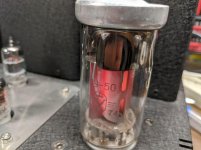
This is an experimental investigation into the feasibility of a very compact point source horn using a tractrix profile and a nice RAAL ribbon tweeter. The design follows earlier methodologies described in the Trynergy thread and also the PRV 5MR450NDY thread. I used the PDF horn plans developed earlier and scaled the plans by a factor of about 0.33x to 0.35x in order to generate the profiles used here. I stretched the nominally square throat out in the vertical and horizontal directions to accommodate the rectangular aperture of the RAAL ribbon aperture. This is a private commissioned design so I have been asked to keep certain info private, such as the specific RAAL model number. But I think one can adapt this concept to almost any ribbon tweeter given appropriate crossover points.

The horn dimensions are about the size of a sheet of letter paper (8.5in high x 11in wide x 7.5in deep). The envisioned frequency range is 500Hz to 20kHz+ with a crossover from 1.8kHz to 2.6khz. Integration with an externa woofer will provide bass below 500Hz.

The midrange will be handled by dual Faital Pro 3FE22 (8ohms) wired in parallel. However, I have found that this combo produces almost too much sensitivity. At 2.0Vrms and 0.5m, the microphone was clipping and my ears were ringing. I think the peak sensitivity was probably about 105dB at 2.83v. As a result, I had to back off the excitation to about 0.63Vrms to keep things bearable for measurements. An observation, consistent with my earlier efforts to use an AMT for a Synergy style horn was that there is very little horn-gain for the tweeter. Maybe 2dB... I think this results from the very small low mass diaphragm that does not pistonically "pump" the air column at the throat vs. a dynamic driver that acts more as a piston and hence experiences typically 10dB of horn gain.

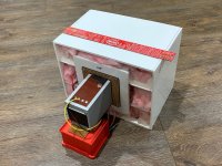
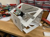
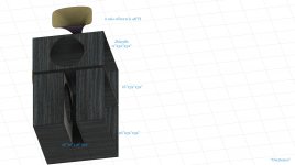
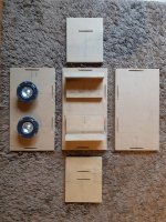
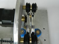
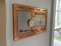
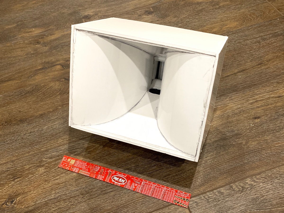
Here is the completed protoype Trynergy horn made out of Elmer's thick paper-faced foam core material. I tried the glossy finish foam core (vs matte) and although it looks great, the hot melt glue does not adhere well as the surface is glossy via a wax coat treatment. If I did it all over again, I would use the matte finish.
834211d1586971177-nano-trynergy-compact-tractrix-raal-ribbon-source-horn-nano-trynergy-raal-photo-01-jpg


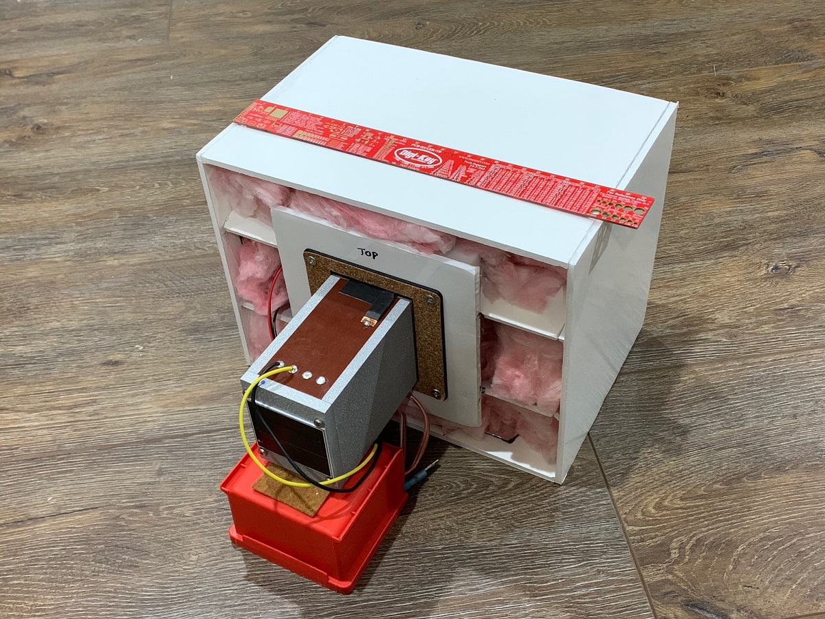
Rear view of the prototype showing open back stuffed with fiberglass in a manner similar to the microTrynergy. This provides enough of an enclosure to allow the mid range to go down to 500Hz with a -12dB/oct falloff. This is exactly where I wanted the crossover to be, so it worked out well. The bass drivers can be anything, but a pair of nice 8in woofers in open face saeled or reflex or TL etc can take this from 500Hz down to circa 50Hz easily. A set of woofers above and below for a WHW (woofer-horn-woofer) arrangemennt might work out real well for a point source system. The horn is surprisngly rigid once all glued together. The two top and bottom driver moutning plates serve large rib reinforcemnts to make the box quite stiff, yet surprisngly light weight.
834212d1586971177-nano-trynergy-compact-tractrix-raal-ribbon-source-horn-nano-trynergy-raal-photo-02-jpg


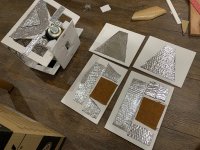
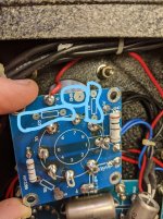
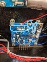
Here are the construction details showing the liberal use of Noico mass-loaded butyl for resonance reduction. The panels and especially the horn walls are very dead sounding under the 'knuckle rapping' test. This will be evident in the very low THD vs frequency plots:
834213d1586971177-nano-trynergy-compact-tractrix-raal-ribbon-source-horn-nano-trynergy-raal-photo-03-jpg


Noico on the side panels as well:
834214d1586971177-nano-trynergy-compact-tractrix-raal-ribbon-source-horn-nano-trynergy-raal-photo-04-jpg


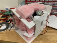
Lot's of pink fiberglass sound dampening is used throughout, some felt right behind the driver magents, and some use of melamine foam at strategic locations:
834215d1586971177-nano-trynergy-compact-tractrix-raal-ribbon-source-horn-nano-trynergy-raal-photo-05-jpg


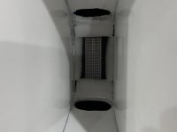
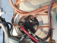
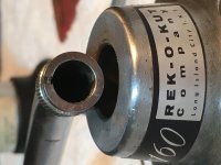
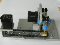
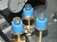
Here is a closeup of the throat and mid-range injection ports (20mm x 40mm at 23mm from throat plane). Throat is approx 40mm wide x 70mm tall. The location was made as close as physically possible given the bezel diameter of the 3FE22:
834216d1586971177-nano-trynergy-compact-tractrix-raal-ribbon-source-horn-nano-trynergy-raal-photo-06-jpg


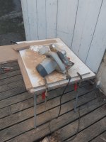
Getting measurements made using UMIK-1 at 0.5m to avoid room reflections:
834217d1586971177-nano-trynergy-compact-tractrix-raal-ribbon-source-horn-nano-trynergy-raal-photo-07-jpg


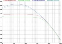
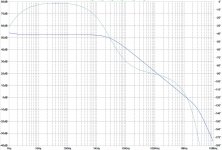
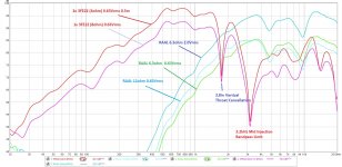
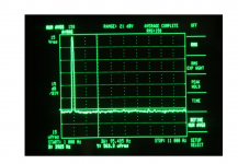
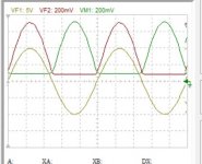
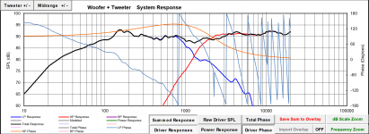
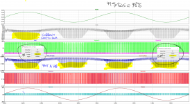
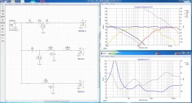
Measured response with freq dependent window (FDW) 6 cycles for mids and ribbon at various excitation levels and impedance taps:
834218d1586971177-nano-trynergy-compact-tractrix-raal-ribbon-source-horn-raal-trynergy-0-5m-measure-plot-08-jpg


The mid range has a sharp dip at 1.74khz, which I believe corresponds to the reflection cancellation from the top and bottom walls at the throat injection point (3.8in). The goal was to get up to 3kHz if possible.

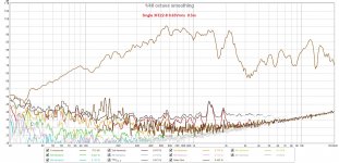
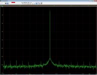
Here is the THD vs frequency of one 3FE22 running at only 0.63Vrms - about 87dB at 1m ( a very comfortable SPL) and showing very low levels of distortion. Panel resonances look well controlled despite 3/16in thick foam core construction:
834219d1586971177-nano-trynergy-compact-tractrix-raal-ribbon-source-horn-raal-trynergy-0-5m-meas-8ohm-3fe22-plot-09-jpg


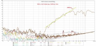
Here is the THD vs frequency for the RAAL running at 0.63Vrms, also showing very low distortion levels. This is equivalent to about 95dB at 2.83v and 1m. The 3FE22's could also be wired in series for 16ohms and that would help to match the sensitivities better and still keep a larger dynamic range and lower distortion:
834220d1586971177-nano-trynergy-compact-tractrix-raal-ribbon-source-horn-raal-trynergy-0-5m-meas-60hm-thd-plot-10-jpg


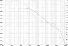
Of interest is the acoustic slope of -18dB/oct on the high pass filter function. This could be very useful for a Harsch XO.

Next steps are to see if the nagging dips at 4.7khz and 10khz can be reduced or eliminated. I think they are wall reflections in the vertical (4.7kz) and horizonatal (10kHz) from the ribbon membrane to the horn side walls.

This will be interesting but certainly shows there is lots of work to be done, but there is promise here for a very compact point source horn. I will try to do some basic EQ and DSP crossover on the mid range. Let the RAAL run via passive high pass but maybe apply some EQ (cuts only, no boost). Will try maybe a 1.7kHz crossover to take advantage of the natural dip there.

Attachments

  • nano-Trynergy-RAAL-photo-01.jpg
    nano-Trynergy-RAAL-photo-01.jpg
    497.3 KB · Views: 7,871
  • nano-Trynergy-RAAL-photo-02.jpg
    nano-Trynergy-RAAL-photo-02.jpg
    472.4 KB · Views: 2,509
  • nano-Trynergy-RAAL-photo-03.jpg
    nano-Trynergy-RAAL-photo-03.jpg
    366.1 KB · Views: 3,318
  • nano-Trynergy-RAAL-photo-04.jpg
    nano-Trynergy-RAAL-photo-04.jpg
    479.7 KB · Views: 1,737
  • nano-Trynergy-RAAL-photo-05.jpg
    nano-Trynergy-RAAL-photo-05.jpg
    297.1 KB · Views: 1,734
  • nano-Trynergy-RAAL-photo-06.jpg
    nano-Trynergy-RAAL-photo-06.jpg
    162.6 KB · Views: 5,752
  • nano-Trynergy-RAAL-photo-07.jpg
    nano-Trynergy-RAAL-photo-07.jpg
    203.8 KB · Views: 1,777
  • RAAL-Trynergy-0.5m-Measure-plot-08.jpg
    RAAL-Trynergy-0.5m-Measure-plot-08.jpg
    258.3 KB · Views: 2,807
  • RAAL-Trynergy-0.5m-Meas-8ohm-3FE22-plot-09.jpg
    RAAL-Trynergy-0.5m-Meas-8ohm-3FE22-plot-09.jpg
    295.3 KB · Views: 1,685
  • RAAL-Trynergy-0.5m-Meas-60hm-THD-plot-10.jpg
    RAAL-Trynergy-0.5m-Meas-60hm-THD-plot-10.jpg
    281 KB · Views: 4,622

Active crossover -Review and suggest

Please review my active Crossover schematic and provide suggestions and improvements.

I do not have experience in designing any electronics, but have experience designing passive speakers. and Crossover the design itself is mostly gathered from online articles. and ESP projects.

Attached a schematic of VituixCAD to that I will be using to simulate the final output
Also mocked up a PCB based on the schematic,

Any help provided is really appreciated.

Cheers

Attachments

  • Active_Xover.pdf
    Active_Xover.pdf
    264.1 KB · Views: 96
  • PCB_Trace.png
    PCB_Trace.png
    134.1 KB · Views: 261
  • VituixCAD_3-way.zip
    VituixCAD_3-way.zip
    8 KB · Views: 55
  • 2-Way.png
    2-Way.png
    37.9 KB · Views: 267
  • 3-way-addition.png
    3-way-addition.png
    37.5 KB · Views: 254
  • PSU.png
    PSU.png
    23.7 KB · Views: 249

Tpa3116d2 output filter advice

I recently ordered a set of what seem to be xm-m562 tpa3116d2 boards to use in a project. My reason for choosing these was that they don't seem to have any output filter, allowing me to build my own using parts I choose. I was wodnering if anyone had any advice on inductor and capacitor selection for this. I am going to be setting up two of them as stereo amplifiers, and one in BTL for a subwoofer. Any advice would be appreciated! At the moment I am looking at these for the output inductors:
MGV1004100M-12 Laird-Signal Integrity Products | Inductors, Coils, Chokes | DigiKey


One other question I have is if anyone knows what the gain setting is on these boards.


PS: I'm new on the forums. If I've made a mistake in where I'm posting this, or if I should have simply posted this to an existing, thread I'm sorry.


rBVaVF0LXc2AAXyPAAHcIqe9hHo917.jpg

Designing an 8" 2-way using the SB23NRXS45-4 and SB29RDC-C004

Hello all!

Before Christmas I decided I would start work on my first speaker design. After some looking around I decided I'll try my hand at building something with the two drivers mentioned in the title. I admit I could have probably done a better job at picking the drivers, alas this is what I arrived at. I have not gotten tremendously far, as I am currently finishing my degree in electrical engineering.

I am planning on placing the crossover somewhere between 1000 and 2000 Hz. I have read a couple of contradicting perspectives about where the LPF on the tweeter should be, some say go high, some say you can take it low.

I have reached a reasonable crossover network. I would however like to ask for some input on how I could improve this, as I am not entirely happy with the phase characteristics.

PS. I am using the late Jeff Bagby's Passive Crossover Designer Excel spreadsheet.

PPS. I could not find .frd files for the woofer I am using so I used the .frd files I found for its 8ohm version, and keeping the differences in response in mind. I was going to measure the impedance and frequency characteristics of both drivers with the measuring devices at uni, but this whole pandemic got in the way.

Attachments

  • Crossover.png
    Crossover.png
    164 KB · Views: 875

Rockford Fosgate Power 500a2

Hi, I'm currently repairing a Power 500a2. The left channel had Q125 & Q115 shorted, and R182 & R163 source resistors visibly overheated/burned. D7 was also shorted. The right channel appears intact, but not fully verified.

I pulled all the left channel source resistors to replace with all matching, and clipped the legs of Q125, Q115, & Q127 (all the IRF540), replaced D7, and set both bias pots fully CCW.

I powered the amp up with a 10a fuse inline and it drew about 0.74A at idle. The right channel produced low, possibly distorted sound. I later realized the RCA input had both shield legs broken between the pcb & RCA riser block, but before I realized this I attempted to bring up the right channel bias. I slowly rotated the bias pot looking for a .05A rise, but never got any increase before going full CW. I turned the bias back full CCW at this point. I then realized the broken RCA when I pushed on the RCA block and got brief loud playback, but I couldn't maintain the connection well enough to judge if it was without distortion.

Nothing got hot at any point. I've now replaced all the left channel source resistors and replaced Q125, Q115, & Q127. I still need to repair the RCAs with a replacement coming tomorrow.

I checked every resistor, diode, and transistor comparing left & right channels and everything was within tolerances, or matched right to left, as far as I could tell. Except...when I check the IRF 9540's Q126, Q119, & Q124 and compare them to Q226, Q219, & Q224, I get a different reading. In diode mode when I connect my positive lead to the drain leg, and negative lead to the source leg, I get 667 for all left channel IRF9540, but I get 753 for all right channel IRF9540. Measuring resistance gives me 550ohm and 618ohm. Source to gate in diode mode I get 832 vs 825 between channels.

The IRF9540 are matching date codes on a given channel, but are different date codes left vs right channel. Is this normal to be that different? The IRF540 seem to give much closer readings between left & right.

Why did my bias adjustment have no affect on current draw?

I have not powered it back up since replacing source resistors & IRF540's. I wanted to see if you guys had any input on anything I might have overlooked. Thank you

Shop Speakers

I live on a farm, and spend a lot of time in the shop working on equipment. Need a set of speakers for 5,000 square feet that will operate in a somewhat hostile environment, hot then cold. Have enclosures for 12" speakers.

Would need them to be a) durable in a hostile environment; b) able to handle 100W or more; c) reasonably priced.

Need not be "high-end", just a lot of bang for the buck. Need the drivers only, not the enclosures.

Appreciate your recommendations.

Dual 5AR4s in Preamp

In a recent review of a power amp the author preferred the sound when the PA was fronted by a PrimaLuna EVO 400, as it provided more of a tube quality. He attributed the "tube-sound" to the dual 5AR4's and not the three 12AXs/AUs, or whatever, per channel.

I'd think this veteran audiophile might have picked up some technical knowledge along the way, even without formal training. Wouldn't dual rectifiers contribute more to having less cross-talk between channels rather than a softer waveform envelope? Hell, even one 5AR4 would provide a pretty stiff PS for a preamp. As I'm not a technical expert myself, I'd be interested in an educated opinion from any AK members.

input selector with ground commutation

Hi, I am trying to design an input selector with ground switch.

Actually, there is a DC leak resistor 1M for the unused input's ground.

In terms of input channels crosstalk issues:
- is it good idea to load the unused input (to its own ground), instead of leaving it floating?

In my schematic we have R11/12-21/22 (10-22 k?).
They load the input signal to its own ground.
But the signal's ground is connected to device ground through the leak resistor (R1/2, 1M)..


Regards

Mystery TO-3 socket with 4 pins

Hi all,

I'm trying to find manufacturer and MPN, and ideally a datasheet, for a 4-pin TO-3 socket. Maybe someone can help? It seems like solder tabs or 3 pins are more common and I haven't had luck so far.

The socket is used on the PSA2 board of an Audio Precision System One.

I don't see any markings on the socket itself so that didn't help. I searched around online and haven't been able to turn up anything either. It looks like the socket at G24727 - (Pkg 4) Compact TO-3 Heavy Duty Socket, but I emailed and they didn't have any information. It also looks like like the image at TO-3PCHD: Major Brands : Socket for TO-3 Case Heavy Duty PCB Mount : ICs & Semiconductors (also see https://www.jameco.com/Jameco/Products/MakeImag/2289655A.jpg), but I again emailed and they don't have information and the linked datasheet is bogus (they told me they will fix it).

So... I'm at a loss. Does anyone have information (ideally a datasheet so I can check dimensions) on a socket that seems to be this one, or at least compatible? Thanks!

Klipsch RP-260f xo upgrade or correction

Hello everyone

I would like to upgrade the xo in my front speakers Klipsch RP 260f to correct a dip between 1kHz and 2kHz in the frequency response (see in room measurements). I think this dip is causing room correction using anthem ARC (genesis) to bring the whole frequency down in an attempt to flatten the curve. As a result the dynamics are lacking when ARC is on. I hope I'm describing it correctly here.

I have no experience in xo design or software, hence I'm asking for help.

Attached are pictures of the xo, schematic sketch (borrowed from Klipsch forum) and arc measurement file.

RP-260f is two way, tw and 2 woofers, I can see that GR research corrected this on a different model RP-8000f by designing a 3 way crossover (2.5 way) to correct the dip as well as the RP600M

Klipsch RP-600M Upgrade

I doubt that replacing XO components with same values and better parts would correct it.

I build my own amps but have no experience in XO design. Any suggestions from experts in this forum would be highly appreciated.

Thanks in advance

Attachments

  • Measurement July 19.pdf
    Measurement July 19.pdf
    336.7 KB · Views: 127
  • XO RP260f.JPG
    XO RP260f.JPG
    75.5 KB · Views: 515
  • XO Schematic.JPG
    XO Schematic.JPG
    77.8 KB · Views: 274

desktop project

Hi,

I'm new to the forum. Working from home now and want to upgrade from my old PC speakers. Planning to build a set of desk top speakers using MarkAudio CHP-70 drivers.

Project goals: simple build, good sound quality for low level background music while working, nice finished appearance. I found the enclosed plans, and I have a few questions. My apologies in advance if all this info is already available elsewhere, but I could not find it easily, and I'd welcome some input from the experienced folk on this site!

1) Can I replace the circular port with a slot port? (I just think it would look better) The cross section of the design is about 5 square inches. Should I make the slot the same cross section? How long should the slot be within the cabinet?

2) Does the design require any input filter circuitry? I plan to initially power it from an old receiver, and maybe later shift to a small dedicated amp with bluetooth.

3) What do you think about using solid wood (I have some maple) instead of MDF or plywood. It would make the project easier for finishing. Maybe just the front baffle?

4) For aesthetics, thinking about a 1/4" or 1/2" round-over of the front baffle - again for aesthetics. Any issues with this?

5) The design shows no internal bracing. I'm assuming this is not needed for a small box like this? - and I don't expect to play it loud.

6) What internal stuffing is recommended? I'm hoping for cheap and easy.

My thought is to try these out without a sub. Maybe I'd add a little one later.

Thanks in advance!

Attachments

The lowdown on cap multipliers

I'm a voltage regulator man, as in comparing the regulator output to some reference and adjusting the output to the wanted value.
But sometimes you see designs that use a capacitance multiplier instead, which basically is an open loop emitter or source follower, as in the attached schematic fragment.

What is not clear to me is how this works under varying load. I guess that the gate voltage is slowly coming up when C4 charges, but to what level?
Also, if I suddenly draw a larger current, the output voltage must drop because the gate voltage stays what it is.

Anybody can offer some clarification here?

Jan

Attachments

  • cap mux.PNG
    cap mux.PNG
    18.6 KB · Views: 302

My Summer Project A Class D amp YAY! >_>

I will preface this as I'm a college ECE senior trying to design a class D power amp. last semester we built a full bridge power inverter and I noticed the topology of the circuits was near identical. I'm going to build a tube pre-amp and turn this puppy in to a 50W hybrid amp for my guitar (Eventually a 100W one for Bass). But right now I want to get the power section down.


I have a question about my efficiency. You'll see from my simulated wave forms that if I look at the AVG power out / AVG power in I have an efficiency of ~98%.
Normally, I'd be super excited about this, but from experience and knowing how dumb I am, realistically the efficiency should be at around 70-80%, like with my power inverter from last semester. Also all of those spikes past a kW make me suspicious. I was wondering if there were any professional engineers on the forum that could tell me a better way on how to measure this efficiency using LtSPICE.
Any Help will be greatly appreciated.
Thanks,
Dan

Attachments

  • powerAMP.PNG
    powerAMP.PNG
    164.5 KB · Views: 230
  • WAVE_FORMS_UPLOAD.png
    WAVE_FORMS_UPLOAD.png
    355.4 KB · Views: 217
  • PWM.PNG
    PWM.PNG
    65.7 KB · Views: 225
  • DEAD_TIME.PNG
    DEAD_TIME.PNG
    42.5 KB · Views: 227

  • Locked
Beginner help requested

Hi All

I’m new to the forum, and have absolutely no experience with electronics.

Here’s my project:

I recently moved into an older house with an intercom system. I repurposed the control panel as a set of hooks for shopping bags etc. and would like to build a guitar amplifier using the guts. The original intercom had a phono in jack, a radio tuner, a speaker, lots of switches, plus the electronics (tubes and other stuff that I can’t yet identify, since I know absolutely nothing about electronics).

Can so help by sharing a source that will teach me the basics (how to identify the parts, and what I need to build a small guitar amplifier)?

Thanks!

Attachments

  • 2463EB3F-5F12-404F-ACA9-EB029B138D7D.jpeg
    2463EB3F-5F12-404F-ACA9-EB029B138D7D.jpeg
    22.5 KB · Views: 155

Replacement for Dynaudio 15W75?

Hello all,

This has popped up in the past but not recently and not with a specific answer.

My tv room has Totem Model 1 speakers and a center channel that was modelled off them.

The 5 inch woofers are Dynaudio 15W75 and the center has some MaxAudio woofers (a Chanadian/Chinese clone of the 15W75 I believe).

Three of the four woofers have torn surrounds and one the is non-functional.

Looking at the Morel CAW538 or MSW144. Apparently Morel borrowed the Dynaudio technology for some of their drivers.

Are there others I should be looking at? Will likely replace all four woofers.

Thanks
Mac

Unreliable source for parts Warning

Hi

Just wanted to share my experience with this site:

Audio High End Store Upgrades Recap

They offer nice Nichicon capacitor kits for vintage amps.

It's a nice page, Professionally constructed and they are located in Sofia Bulgaria I presume.

On the 16th February I ordered a capacitor kit for recapping a Pioneer Amp.

The order was processed the nest day and I received an email with shipping status, but no tracking number since they sent with standard mail.

Since the package didn't arrive till now (4 weeks later), I sent an email asking what was going on with my order, and they replied telling for me not to worry.

In the meantime I searched for reviews and found experiences from another buyers that the orders take ages (2-3 months) to arrive and sometimes items are missing or not correct and You have to wait another 3 months for the missing parts. Who did receive the orders, also tell the parts received were measured and are not counterfeit.

In modern days, it's totally unacceptable to wait 3 months for mail between two European Countries, even with the Corona Virus Crisis going on.
I don't know if I was Fu#### or if the package did somehow got stolen or lost...It doesn't matter now.

Yesterday I opened a dispute process with Paypal and today I received an email from Paypal confirming the refund.

Crossover Critique

I'm putting together a pair of three way speakers using some inexpensive Dayton RS series drivers. I'm a newbie at passive crossover design but I've spent some time with couple different versions of software and have come up with a design I think may work in XSim. I haven't taken actual measurements of my drivers yet (haven't had a chance to break them in yet) so I'm using the .frd and .zma files available from Parts Express as a learning exercise and plan to tweak this design once I have the speakers assembled. Also no baffle step correction or driver alignment yet either.

The woofer and mid are both 8 ohm drivers and the tweeter is 4 ohm. I've been trying to keep both the efficiency and the impedance of the speaker up, but I've been struggling with the impedance. I was hoping to end up with 8 ohm speakers but these seem to be looking more like 4 ohm.

Any hints or suggestions are welcome! I've attached the XSim file and the driver data as well.

Attachments

Passive radiator from China?

Hi, not sure this is in the correct section, but making a full range Bluetooth speaker, so lets see.

Curious if anyone has successfully used the cheap ones from China? I've been interested in the size of the one at banggood, but don't really want to want an eternity for it to arrive and it sounds like garbage.

2Pcs 60x90MM Low Frequency Radiator Vibration Plate Bass Passive Speaker Sale - Banggood Mobile404 Not Found
Projects by fanatics, for fanatics
Get answers and advice for everyone wanting to learn the art of audio.
Join the Community
507,811
Members
7,889,384
Messages

Filter

Forum Statistics

Threads
406,292
Messages
7,889,384
Members
507,811
Latest member
Cystore