crossover point suggestion

Hello,
just got DATS V3 doing some measurements to design the crossover, need recommend for crossover point, slope filter...etc. Am going for 2 or 3 ways with a RCF HF96 horn. Could not find the recommendation in the spec sheet.
Dayton Audio D250T-8 1" Titanium Compression Horn Driver
Thanks,

Attachments

  • dayton D250T-8 specification.JPG
    dayton D250T-8 specification.JPG
    128.1 KB · Views: 210
  • dayton D250T w no horn.JPG
    dayton D250T w no horn.JPG
    171.9 KB · Views: 204
  • dayton D250T w horn.JPG
    dayton D250T w horn.JPG
    169.5 KB · Views: 209

For tube lovers-Henry Wolcott Amplifiers from JBL PL100

Update H.Wolcottmanual 2015-10-24
I'm going to a calm live in the age of 65 + I will give you all info I got about my amplifier system .
The book /manual I have made about Henry Wolcotts amps from 1960 JBL PL100 to the prelude of the Presence amp.

Henry Wolcott amplifiers by test[/url] with schematics
ISSUU - H wolcott ny 2015 10
my amp system
https://sites.google.com/site/jblpl100/

ISSUU - Additional manu codes 2014 04 by test

PL-100+ Pa250 Photo by bassamps | Photobucket

E88CC (ecc88) TELEFUNKEN, SIEMENS GOLD PIN

I have some e88cc (ecc88,6DJ8,6922)) excellent long life, low noise gold pin double triodes to sell.
All measured on Hickok tester. 100% value is 6750mohms
From left to right 1 and 2 triode
1 Telefunken e88cc 8300-8500 mohms
2 Siemens e88cc 8700- 8250
3 Seimens e88cc 7000-7150
4 Siemens e88cc 8900-9000

price 49 € for Siemens and 59 for Telefunken

Attachments

  • e88cc oglas.jpg
    e88cc oglas.jpg
    412.8 KB · Views: 427
  • e88cc toglas.jpg
    e88cc toglas.jpg
    355.3 KB · Views: 413

Audio/acoustics career path question

Hey all, I'm interested in any advice, opinions, and experiences on this one, so please chime in with any insight you have.

I'm currently considering re-education to further my career path.

I have a bachelors degree in music (composition was the focus) where I learned quite a bit about digital signal processing, psychoacoustics, and basic musical acoustics.

I've been working (fairly happily) as a cook for the past 10 years or so (during my music degree too). But as time passes I keep coming to the realization that this field is not where my heart really lies. I'm a foodie nerd who loves creating crazy food (read through www.erichedekar.com for a virtual taste) but it's just a pleasure for me, not my true passion.

Lately I've been re-engineering my car's audio and acoustics (the project is seriously too large for what it needs to be, but I'm having so much fun doing it). This has led me to remember the passion I have for acoustics and audio.

I'm considering enrolling in (well, I'm fairly sure I'm going to at this stage) a bachelors degree in engineering to get the technical understanding of this world more solidified. The school that I'm going to (for various reasons) is Simon Fraser University SFU Home Page - SFU - Simon Fraser University which specializes in electrical engineering.

My question(s) to this forum audience is/are: What realistic audio career options are available to someone with a music degree and an electrical engineering degree? and which of these SFU engineering paths would probably be best for this:
Electrical Engineering,
Systems Engineering,
Mechatronics/Business Dual Degree,
Physics Engineering
All of the advisors I talked to were unsure of which direction would be most suitable.

I am also keeping in mind the possibility of enrolling in a local masters degree in acoustics and noise research (this would be after my undergrad in engineering), but that's far enough down the road that it's just a back-burner thought.

The jobs I can think of that really interest me would be something like amp designer, musical instrument engineer, speaker designer, acoustical consultant for a construction project, etc....

Any thoughts or advice you can throw my way would be great. Thanks for reading.

6E6P-E spud amp - how it can sound?

Hello guys, I have a 93dB open baffle speakers and momentally a 4P1L PSE amplifier with something like 3.5 watts of output power.
I consider making a little spud amplifier wth the 6E6P-E tube, because I have two 5k 25mA output transformers lying around. What do you think?
I think something like a 1.5w is possible to squeeze out of this tube in triode.
I have read your other guys posts, but how it actually sounds? Can someone describe it in detail?
Thank you very much. Best regards, Michal

Current-Amp to drive bass guitar cab?

Hi!

I have a 4x10" Ashdown ABM bass cab driven by a Hughes&Kettner bass top. I just had the idea of modifying the bass top to act as a current amplifier with 8 ohms output imepdance. Has anyone tried this so far? Obviously we're not talking about HiFi here!
I once had the cab driven by a Tube Amps 8Ohm output and although i didnt hear that much difference as i expected, i think, the sound was a bit less harsh even with the amp not driven into saturation.

Phase measurement

I made several sweep measurements on SB26ST-C0000-5 tweeters and two phase curves was generated within each drivers.

phase SB26ST-C0000-5 mod 1.jpg
phase SB26ST-C0000-5 mod 2.jpg
Note that SPL curves are the same.

The first one happened a bit more often. I was questionning myself if it's the drivers or something else causing this.

I decided to test the woofer to compare. There was only one phase curve.

I tried other repetitive measurment on Mirage m790 HF portion and I obtained two phase curves again.

phase mirage m790i HF mod 1.jpg
phase mirage m790i HF mod 2.jpg

All the previous measurements was made with Omnimic V2 and laptop directly plugged in Cambridge audio 640A V2 (I also replaced faulty relays with no change in measurement) at 1 m.

I wanted to be sure that these two initial measurements were good. So I tried repetitive measurements on my other system (Monitor Audio BR6, Moon 220i and Moon 300D). There was only slight variations on phase but nothing alarming. I also tested the famous SB26ST-C0000-5 on the same set up (except the speakers duhh..) and the two same phase curves was identical to the first ones.

Not sure of what was going on.

So... does anyone ever seen this issue and is it the drivers that cause this?

Thank you.

The "Ear-gasms" - My try at a line array

Having issues with pics right now so will add when I can.

I have finally had the chance to tinker with my line arrays. Last year at the MWAF I picked up 50 of the Lavoce 3" full range drivers, I kinda had in the back of my head that I wanted to augment the low end so later on I purchased 20 of the P.E. 6 1/2 poly cone buyout buyout to try.

Late last year I put together a couple test boxes, 1 had 4 of the LaVoces and the other had 2 of the 6.5's. I ran them with a couple of the P.E. DTA 120's and a Minidsp. I was quite impressed with the combo and decided that is how I would proceed.

Fast forward to 6 weeks furlough and I have made good progress.

I decide to go with 24 of the 3" and 9 of the 6.5's per side. I had baffles made out of alum (4 1/2 x 80) for the FR drivers and put together a test box. I made a separate box to house 8 of the buyout woofers.

I finally had a chance to put together and listen to the system. The left side is running the full stack of 24 Lavoce and 8 woofers. The right side is is running last year's test boxes with 4 Lavoce and 2 woofers.

After spending about 4 hours with gain, delay and eq I had it dialed in to acceptable listening for my barn.

All I can say is WOW!!

I sampled just about all of my music collection and am amazed at the amount of detail that I have been missing.

Robbie Robertson's "Somewhere down the crazy river", Roger Water's "Radio Kaos" album and few others were sublime...

Marah, Martin Zellar, Gear Daddies, Beat Farmers all took on new life.

Can hardly wait to start building the final product.

Will post pics and update when I can.

Faital W10n8-700 TH?

Hello,
Bought 2 of these awhile from a "buyout" planning for small 2ways PA top, end up did not need to. Could a PA sub TH worth a try?

Attachments

  • ts.JPG
    ts.JPG
    31.5 KB · Views: 410
  • input.JPG
    input.JPG
    66.2 KB · Views: 399
  • acoustical power.JPG
    acoustical power.JPG
    48.4 KB · Views: 391
  • displacement.JPG
    displacement.JPG
    49.3 KB · Views: 393
  • group delay.JPG
    group delay.JPG
    47.3 KB · Views: 388
  • FaitalW10n8-700.txt
    FaitalW10n8-700.txt
    1 KB · Views: 62
  • faitalpro.jpg
    faitalpro.jpg
    100.7 KB · Views: 186
  • phase response.JPG
    phase response.JPG
    64.4 KB · Views: 164

Lubricating CD player's turntable motor (how often)

I have several CD players from the late 1980s (mostly Philips). These use either the std. CDM-4 "toy" motor or the better Hall-effect motor.

These CDPs have mostly been in storage all these years. I do realize that oil degrades regardless of use/non-use.

Given low to normal use (mostly low), how often should the main (turbtable) disc-spin motor be lubricated?
What are signs to look for that the motor needs lube?
What is the best oil/lube to use?

Thanks.

Critique my soft-start power supply design for the Adcom GFA-555

Yes, it's another soft-start design! 🙄

This one is meant to be as fail-safe as possible, both for the amp and the soft-start circuit itself; it's relays, and inrush resistor. I'm employing a lot of Boolean, pinball-machine transistor/relay/optocoupler logic here; something I am not very fluent in, so it's been a week of obsessing and staying up till 6AM trying to figure it out! :headbash All the "ANDs" and "NOT's" and "ORs"...and the "If such-and-such a condition is TRUE, then don't NOT do the THING"... :crackup: ugh it hurts my brain.

But I think it works!

Hoppes-Brain-GFA-555-Soft-Start-II-2020.04.16.png


Download "The Spice" and tell me if I am missing anything.
Hoppe's Brain GFA-555 Soft-Start
The various voltage sources are set up to simulate normal operation. To make things abnormal, tweak their parameters and you can test the logical functions of the circuit. For example, you can test for chattering AC condition by pulsing the 24V unregulated supply voltage. You can simulate the completion of capacitor charging by pulsing off the voltage seen at the optocoupler that monitors inrush current.

Commercial disclaimer: This is intended for power supply boards for the Adcom GFA-555 that I will be producing and selling on my website. However I am happy to share the schematic for anyone to use or modify. I hope it's a good design that people find useful.

One issue I wanted to address, is the possible destruction of the inrush resistor or relays, if there should be a fault condition such as a brown-out or chattering AC input. Many designs do not reset the relay timer quickly enough when power is lost, and when power returns, the relay stays on and there is no soft-start action. This one resets in a couple milliseconds.

I wanted to get away from the assumption that just because time has passed since the power was applied, that the capacitors are charged and it's safe to click in the bypass relay. This condition is merely inferred! Why not test to see if this condition is true before clicking in the relay? I found a few circuits on the web that monitor power supply capacitor voltage, and then close the relay when they are mostly charged. However, this still doesn't get to the root of the issue, which is...

The relay should not click in until the current through the inrush resistor is low. Time is not the issue, nor is power supply capacitor voltage. It's the current through that resistor, indicated by the voltage across that resistor. When that is low, it's safe to pull in the bypass relay.

This design monitors a handful of conditions that guide it's operation. (Opto-couplers are neat-o!)

  • The 12VDC power supply is good. (And it's safe to operate the relays with sufficient force.)
  • AC power is good (Inferred by DC power supply to the soft-start being good)
  • Either the power switch is on, or the remote trigger is on
  • The inrush resistor is not overheated
  • The current through the inrush resistor is low, and therefore the capacitors have charged.
  • 1 second has passed with all parameters OK before either relay will click in. (Chattering is limited to 1Hz)

Both the power relay and the soft-start relay have one-second time constants, but this is nothing to do with waiting for the capacitors to charge. The timers only serve to limit relay chattering to 1Hz. Both timer's trigger states are held logic high, by default when power is lost, and will not start the timer unless conditions are met.

Here are the fault conditions I am trying to handle, do you see anything else I should be considering?

  • Brown out, voltage low: DC power supply will be less than 10.6V and so power trigger is held high and timer will not start
  • Brown out, voltage on threshold of keeping DC power supply OK: Power relay may start, but it will momentarily drag supply voltage down, causing relay to click out again. This repeats at 1Hz. I need to physically build the circuit to see if the relay actually pulls in, or if it resets before the contacts actually touch. It could be a problem if it makes brief momentary contact over and over again.
  • Brown out, power fluctuating: Relays will both cut out when power goes below a certain level. The relays will click in if power comes up again, and they may cycle in and out, but at a maximum rate of 1Hz.
  • AC power chattering: Power relay timer self-resets and will not start until power is steady. If the power remains on for longer than 2 seconds, both the power and soft-start relay will click in, and both will reset if power is lost again.
  • Remote signal or power switch chattering: Power timer resets and will not start.
  • Capacitors NOT charging up, or something is wrong with the amp and causing excess current draw: Power relay will come on, soft-start relay will not. Inrush resistor will heat up, and eventually 130C thermostat will open, causing everything to turn off. (Power resistor can handle 270F, so the thermostat should open well before that, even if it is rapidly heating.)

What am I missing here? There must be something!
Do I need to pepper some 10nF compensation caps around the switching transistors, or will they be OK? I haven't used a high-side MOSFET switch before, I like it! Is 470K alright for a pullup? I am trying to make the remote power sense optocoupler very sensitive so it will operate decisively, and I don't want the MOSFET to ever be unsaturated.

korg b1 help

hi i need help with korg b1,can any body recommend a 24v power supply for the preamp unfortunately here in the uk we cannot get the triad power supply recommended, i have got it to work with a 24v smps i had from a previous project but had to use a choke and a few rc filters to keep it quiet (not ideal) still a bit of low noise at 0 volume !
also this is gonna sound dumb, it quotes (Remember that the preamp is phase-inverting. In order to get the correct absolute phase coming out of the speaker you must invert the phase after the preamp. The easiest place to do this is at the loudspeaker.) in the pdf, does that mean (+to -)(-to+)at the speaker terminals thanks a layman

Grounding help Circuitbasic LM3886 and Mark Johnson PSU

I just finished building an LM3886 chip amp with the amp boards from circuitbasics.com and Mark Johnson’s PSU board. I thought the amp was fine when I first tested it on my inefficient Minimus 7 test speakers, but when I hooked it up to VERY efficient Cornwall’s I noticed a lot of what I think is ground noise (crunching, whirring, and some radio frequencies) and its pretty loud. I first confirmed 0mv DC offset.

Since I didn’t have the PSU from circuitbasics.com, I thought that I could create a “ground hub” from a plastic terminal block by splitting the ground. The PSU ground, signal ground, speaker ground, and PCB ground all connect to this and I am now realizing this is NOT a good grounding scheme.

I currently have two rca inputs that go into a switch for input 1/2 and then into an Alps Blue pot which has the ground tabs connected and a wire connecting to the ground hub. I did upgrade my wires to shielded cable which helped.

Hoping to get some help on this as i have read multiple forums and looked at a lot of pics and I can’t find a similar wiring to mine.

Thanks!

Attachments

  • 340411F6-D1AC-4B4A-8D1D-FFE9DD3A8C78.jpg
    340411F6-D1AC-4B4A-8D1D-FFE9DD3A8C78.jpg
    1 MB · Views: 334

Have time to desk check my power supply design?

I've been bread boarding this power supply over and over for a month switching things up and I've settled on the design shown here. I used the Quasimodo method to determine the snubber for this Antek transformer.

Would any members have a kind second to desk check it a little?

I do have one specific question though and that is that I chose to establish the virtual ground for the AC filaments using the safety ground, not the audio ground established at Star B or the "dirty" peak voltage raising cap ground established at Star A. Is this ok to reference the filaments to the chassis instead of the audio ground (which is floating from the chassis)? I figured as the filament wires snake around and hug the chassis it was better to have those referenced the same and not get them involved with the establishment of the clean audio ground.

Newbie here.

Attachments

  • DeskJobV10.png
    DeskJobV10.png
    348.6 KB · Views: 159

Question re: transformer for basic bi-polar power supply

I did several searches and was surprised I couldn't find the answer to this, it's pretty basic. The closest I could find was this thread

I'd like to build a basic bi-polar power supply for something similar to a CMoy or Grado RA1 circuit. It's a very simply amp, so I'd rather not spend much money on it. I've attached the circuit I'd like to breadboard, just substitute 115V for the transformer primary.

Regarding transformer selection, I've seen +/- 15V in the wild, but few and far between. Is it acceptable to use a 30V CT, with the center tap at 0V? I was looking at this Hammond unit 166G30: 166G30 Hammond Manufacturing | Mouser

...or this flat pack style transformer:
LP-30-400 Bel Signal Transformer | Mouser

Any input would be much appreciated. Thank you.

Attachments

  • 12-Volt-dual-power-supply-circuit.png
    12-Volt-dual-power-supply-circuit.png
    13.5 KB · Views: 104

Sansui AU-111 fine tuning and balance/FR problem

Hi everyone,

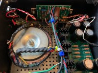
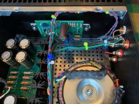
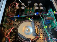
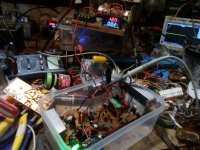
I'm finishing rebuilding a good old Sansui AU-111 from the early 70s, and now that's it has been thoroughly recapped, retubed and biased, i'm fine tuning it, hence I need some help.

Sorry for the long post but I wanted to provide as much information as possible, so the questions are a bit scattered through the post (the questions are in italic)

First thing I've done was to change the more than unbalanced volume pot by a 250K cms commuted one (with center tap), now both channels are exactly the same.
The old 250K pot measured 150K on both channels (IN to GND) and CT at 95k (from IN to CT)
Speaking of this, witch value should really be the center tap? 75K or 125K? (as it's a commuted pot I can choose my CT point).

-I also shielded the power switch zone witch reduced induced hum significantly, still i'm getting audible hum with my efficient Heresy III at listening position.
When disconnecting Preamp stage from the main amp stage, I do not have any hum, perfectly quiet.
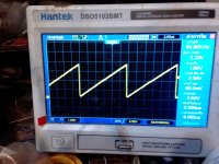
Where should I look at to hunt down this 50hz hum (frequency tested on scope)


-Last problem I have is related to the treble pot unbalance pointed by smurfer77 on AK forums. In fact my outputs are unbalanced and frequency response all other the place. All the tests I've done where made with an Analog discovery 2 using both Waveforms and Thatstuffmade audiosuite.
The balance pot was set at the middle position, treble and bass switch to "defeat".


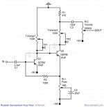
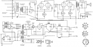
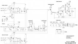
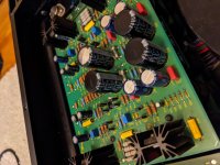
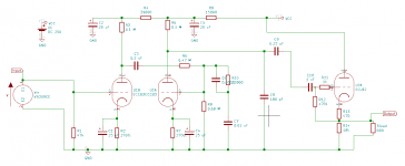
This is the preamp stage where trouble happens.

First thing I've done was to check if my balance pot was balanced by injecting signal directly at the volume pot input.


perfect balance on both channels, phase rotation is probably due to the fact that I'm using both generator outputs (I do not have this phase shift when inject mono signal on both channels)

When injecting from the treble pot center tap here's what I got:


clean

Then when injecting on the Tape monitor input (bypassing the phono stage)


Unbalanced output.

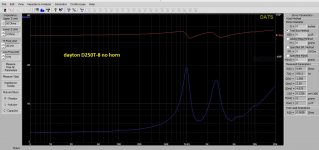
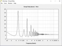
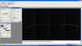
Now comes the frequency response curves:

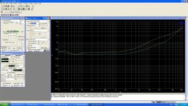
When injecting from Treble Center tap:


Volume pot at 90°


Volume pot at 180°


Volume pot at 270°

The channels are well balanced, the response is rolled of at the low frequency (I'm bypassing the feedback stage) and changes with volume.

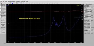
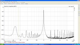
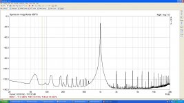
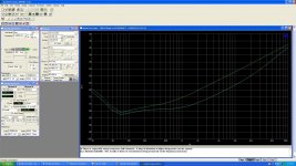
Now when injecting from the Tape monitor input:


Volume pot at 90°


Volume pot at 180°


Volume pot at 270°

Here the frequency response are full but varies with volume and the channels are not balanced anymore.


So my problem lies on the feedback circuit on V2/V3 second triode witch leads to the Treble pot witch sets the feedback loop resistance.
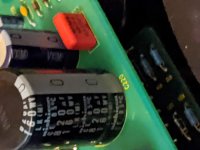
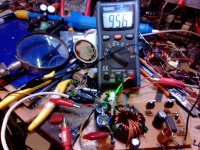
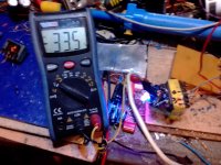
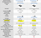
Here are the pot measurements on different points (I made the measurements with the pots in circuit)


I have a significant difference in resistance between the two pots, the left one having more resistance, so I'm assuming I need to add resistance to the right one, but where should I put this resistance?

1. between the pot and the input (from v2/V3 first triode Cathode)


2. between pot Center tap and V2/V3 second triode Grid)


2. between pot and Feedback


I hope someone might help me on those issues.

Matched polystyrene > 8uf capacitors

Two pairs of originally 8.2uf 10% K71-4B polystyrene capacitors.
They are used but not abused. I measure only 0.01uf difference from when I initially measured them some years back (same Fluke 179) so they are quite reliable

pair values:

pair one: 8.54 and 8.61
pair two: 8.84 and 8.90

They are quite big as expected:
Dimensions 85mm X 42mm

SOLD

Attachments

  • P3070997.JPG
    P3070997.JPG
    612.9 KB · Views: 317

JLsounds I2S over USB

For sale JLsounds USB board with I2S and SPDIF outputs. It has the NDK NZ2520SD clocks. Full functioning of course, part of 9028 DAC that will on sale, so no use for it now.

Edit: according to current revision numbering, it's a mkII version (mkI being the one with espresso clock I guess), while currently there is mkIII on sale (green silkscreen).
It's firmware is 3.28 (device info) so supports native DSD (as all with firmware 3.06 and above). Of course no problem paying SACD and hirez with 9028

SOLD

Attachments

  • jlsounds.JPG
    jlsounds.JPG
    635.1 KB · Views: 233

GD Parts Class A Single End EL34 Kit

Hi guys,

I'm turning 50 and I have a present to choose 🙂

I have a limited amount of electronics knowledge in so far as, I've successfully built several Seventh Circle Audio pre amp kits for recording, but the instructions were great and if something had gone wrong, I wouldn't really know where to start.

I'm looking for advice on this: Hifi DIY Kits Class A Single End EL34 Tube Integrated Amplifier Vintage Tube AMP | eBay

It's at the top end of my price range and looks easy enough to build. Does anyone here have anything to say about these?

Also, I'm using a Cambridge Audio DacMagic 100 with Tannoy Eclipse 3's and a Sony amp with a dodgy volume knob. I notice the tube amp on ebay is 12w per channel and my speakers are 8w. Would this be a problem?

Thanks in advance for any help.


Alex.

Audio Amplifier left speaker banana plug connector cutting out or shorting

Hi Everyone,

I have a NAD C320BEE Stereo Amp, it's around 15 years old, sounds great and up until the past few weeks has been rock solid. What is happening is the left speaker output (positive terminal I think based on the wiggle test) will intermittently cut out, or sometime slowly fade until it's out. Sometimes, a wiggle of the left positive connector brings it up, other times it does not. Of course I have swapped speaker cables (banana plugs) and speakers and all that logical troubleshooting, same issue.
I am fairly comfortable trying to troubleshoot along the circuit path, maybe, if someone had some idea of where to start, or what I should be looking for. I have access to a scope and meter and all that stuff. I do have the service manual for the amp with circuit diagrams and can share/post them if that's allowed(?)

Thanks for looking and for any help!

Hypex Ncore NC500MP 2x500W Power Amplifier

SOLD!!!

Hello
For sale my test amplifier with two hypex Ncore NC500MP boards installed.
Dual mono a,mplifier in a modest but funcional case.

Peak Output Power is 2x500W @ 4Ω, 2x400W @ 2Ω and 2x270W @ 8Ω.
The power amplifier has been in my testing bench for no more than 50 hours. almost new.
No scratches, no damage.

HICON XLR inputs and standard binding posts outputs. Jantzen silver PTFE wires for audio outputs.

External dimensions 280x250x90mm (WxDxH) Weight 2,5 kg.

SOLD!!!


Re-furbishing Decca Corner Horns

I recently acquired a pair of Decca Corner Horns. The owner had fitted them with Kef B200s and T27s and they sound very nice. However I am toying with the idea of fitting Tannoy dual concentric 8" drivers.

Question - the B200's bottom end is rated at 25Hz and the Tannoy at 40Hz. And Decca's spec for the speakers claims 30Hz. Would the horn loading extend the ability of the Tannoy to reach the lower figure?

Which begs the question - how is the frequency range of a driver determined?

For Sale: ACA amplifier

This is a little used ( about 50 hours) ACA that I don't need anymore.
I'm selling to cover the cost of the parts and materials.
It is built on a Mini Dissipante 3U 250mm All aluminum case. The main transformer is a Hammond and the raw supply filtering comprise of 80mF 35 V Nichicon KG caps (8x10000uF). Biased at 1.6A and works great.
Shipping is from 06851 of about 22lbs.

Asking $450 plus shipping.

Attachments

  • IMG_5586.jpg
    IMG_5586.jpg
    914.6 KB · Views: 956
  • IMG_5587.jpg
    IMG_5587.jpg
    929.5 KB · Views: 922
  • IMG_5588.jpg
    IMG_5588.jpg
    887.8 KB · Views: 901
  • IMG_5589.jpg
    IMG_5589.jpg
    859.8 KB · Views: 886
  • IMG_5590.jpg
    IMG_5590.jpg
    744.6 KB · Views: 886
  • IMG_5591.jpg
    IMG_5591.jpg
    791.1 KB · Views: 514

SoundDynamics Loudspeaker Crossover upgrade??

Hi All.

Looking for your advice.

I learned that the principal partners at Cerwin Vega had a falling, and, after departing, one of them formed SoundDynamics.

I have a pair of SoundDynamics 2 Way Loudspeakers.
Largish cabinets which feature 10" Woofers and 1" Tweeters fitted with wave guides.

They are very satisfying when it comes to bass reproduction but lack in treble area. Compared to other Speakers I own they are quite flat in the higher frequencies.

I ripped out one of the crossovers this weekend and list the parts as follows:

Resister: Cheap sandcast example marked with the values 7 watt, 2 ohm.
Capacitors: One Intercap 4.7mfd 250v & a smaller Intercap 4.7mfd 100v.
Inductor: Air core, thin copper winding, 35mm diam, 15mm centre hole, & 7 mm high. Scratching the red finished wire winding revealed a shiny copper color.

What do you recommend in terms of upgrading the crossovers?

cheers

Cliff

Whats this capacitor for?

ElecraPrint.PNG

This is an amp that I am currently bread boarding, it is a project suggestion on the Electra Print web site for a SE 6BX7 amp....

My question concerns the 450uf el cap that connects from B+ to the cathode of the 6BX7. Is it possible that this is here by design to inject some of the power supply ripple into the cathode, so that it can cancel out with the ripple on the plate, for better PSRR?

John Broskie does something similar in this article:

But in the Broskie article the value of the capacitor is a carefully chosen ratio of mu, at 1/mu (+ 1 I think). But on the Electra Print schematic they just seem to have jammed in a big capacitor

Parafeed-Amplifier Design

John Broskie does it again in this recent 300B amp:

Two-Tube Single-Ended Amplifier & Speakers (halfway down the article)

All for PSRR benefit?

How to Mod Williamson 1949 for ECC83 & EL34

Hi,
New to the forum. Been wanting to do some audio DIY for over 15 years, and I'm finally taking time to do it. I've acquired parts over the years, including some nice caps. But, a primary thing I would like to do--besides making a nice-sounding amp--is use my hard-earned tube stash, which consists of some nice ECC82, EEC83, ECC88, EL34, and KT88 variants. (Also have some 6SN7's and 6V6GT's.)

The following schematic link is to a redraw of the Williamson 1949 amp by Keith Snook, who I will thank up front for his work, as clear schematics seem hard to come by. Thanks Keith!

http://www.keith-snook.info/amplifier-hifi-schematics/Williamson amplifier 1949.pdf

My question, of course, is can this circuit be made to use some combo of ECC82's and/or ECC83's with EL34 or KT88 output tubes in lieu of the ECC81's and KT66's? If so, can it be done without sacrificing sound quality? Or, should I be looking at another circuit? I don't have any transformers yet, so...

I'm self taught and can read basic tube specs and get the voltages into spec (I think), but I don't trust my ability to design circuits--yet. Any advice is appreciated.

Best,
Louis

ICEPower ASX series thermal pin/shutdown temp

I have some 50ASX2 SE units and a 125ASX2. The darasheet and designer manual for the 50ASX2 shows the thermal pin and describes its electrical operatiion. However it does not say whether the pin is active before shutdown so that it can be used to enable a fan. I thought I remembered that it operated at 40 degrees C and that shutdown is at 50 degrees C but I cannot now see that in any of the documents.


Does anyone have any experience of using the Thermal Pin in this way?

Harman/Kardon HK6500 - white noise (hiss) in output after recap

Hi,
recently recapped this entire amp + new output transistors (matched within tolerance of 10).
The amp still hisses in the speakers. It's only audible at max volume. It's very quiet from Tuner/CD outputs, but very loud from phono section (nothing connected).
I heard this could be caused by transistors before the main stage, there are couple of those in the preamp, they run rather toasty (60-70 degrees) and the board is discolored around them.
Anyone has any tips? The Pre-amp transistors are 2SA1124 + 2SC2632. I can replacement ones by On-semi for pretty cheap if needed.
Thanks!

Seas tweeter - terminal broken

I am restoring a prob 18 year old custom built 2 way bookshelfs.

Long story short, there was a long screw in the enclosure that pierced the terminal of the tweeter which is a SEAS 27TFF.

See pics: Imgur: The magic of the Internet

The terminal is supposed to be fixed, and the housing is slightly broken. I can't see where the terminal should hit another piece of metal - the housing looks all plastic to me.

Any ideas on how to repair this? seating it back in looks like it would hold actually, but for how long....

Couple of questions regarding wiring & bridging vs parallel.

I havent bridged my subwoofers before, and looking at new amps has revealed my lack of knowledge to many things


I've been looking for some rather cheap & lightweight amplifiers for bass duty (Not the best combination, I know) to replace my current amps (Pro-line 3000 & Crown XLS 5000) to less weighing ones.
I know I will be getting a bit worse bass than what I have now, but thats a trade-off I am willing to make to reduce my 75kg rack to a 24kg one.
I will be using 1 amplifier to power two Fane Colossus 18XB drivers (8ohm /1000w rms/2000w program/4000w peak) in a reflex cabinet tuned from 40 to 80hz.


So far the T.amp TSA 4000 looks to be the best option (The only options for a new amp really being between T.amp TSA 4000, T.amp TSA 4-1300 & Behringer NX 6000), giving 2x 1000W 8ohm, 2x 1500W 4ohm or 1x 2865W to bridged 8ohm and weighing 12kg.

Wiring: A lot of amplifiers ask for a +1 & +2 connection when bridging. I've only used +1 & -1 cables so far. Do I only need to switch the end of one of my speakon cables (making it a +1 & +2 to a +1 &-1 cable, like in the first picture) for everything to be alright? Or would I have to re-wire the cabinets aswell.


TSA 4000 and bridging; The bridged option says to be 8ohm. My drivers are 8 ohm each, i've placed two speakon sockets on the back of each cabinet to allow for a parallel connection, making them 4ohm each when connected to each other. Will there be problems if I try to connect this 4ohm setup to the 8ohm bridge mode?


Since I want a bit more power than the rated RMS, How would I go about connecting these two cabs to either get a bridged connection or to get the 4ohm per channel to be able to receive 1500w @ 4 ohm per cab?

I am not really sure how to switch between the 8 and 4 ohm options from the amplifier, is it the parallel option?


T.amp TSA 4000
https://www.thomannmusic.com/the_tamp_tsa_4000.htm


Fane Colossus 18XB
Fane Colossus 18XB-8 Ohm – Thomann United States

Many thanks!

Attachments

  • 1.png
    1.png
    33.7 KB · Views: 266
  • Screenshot_2020-05-16 the t amp TSA 4000(1).jpg
    Screenshot_2020-05-16 the t amp TSA 4000(1).jpg
    131.3 KB · Views: 187
  • Screenshot_2020-05-16 the t amp TSA 4000(2).png
    Screenshot_2020-05-16 the t amp TSA 4000(2).png
    19.6 KB · Views: 209

Sony TA-3200F: huge output DC offset

Hi all,
'ts been a long time. How's everyone doing?

I'm working on this amp, which I recapped, adjusted, measured (fairly well - enclosed), and played for hours, until there was a POP!, and I lost both channels.

Smelling something too hot for comfort from the speakers protection board (it's an early model), I measured DC voltages coming into the protection board from the outputs and I get 0.85V for one channel and 1.38V for the other. Obviously, humongous. No wonder the protection boards clamps both channels to no output (base of Q110).

Obviously, at the end of my adjustments, the values for bias and offset were pitch perfect.

It seems some sort of failure occurred, but why on both channels, and why so similar a failure?

I am torn between pulling final Qs out (which would be painful, as they're soldered), and investigating the differential input to see if a large unbalance has occurred (but why?). Maybe do some voltage-resistance on all stages, starting at end, against schematic.

Any input welcome!
aR

Attachments

  • Sony TA-3200F Ampl vs Freq - ADJUSTED - 03-08-2020.JPG
    Sony TA-3200F Ampl vs Freq - ADJUSTED - 03-08-2020.JPG
    288.9 KB · Views: 367
  • Sony TA-3200F ARTA 1.4V in 2.8V out L - ADJUSTED - 03-08-2020.JPG
    Sony TA-3200F ARTA 1.4V in 2.8V out L - ADJUSTED - 03-08-2020.JPG
    197.2 KB · Views: 376
  • Sony TA-3200F ARTA 1.4V in 2.8V out R - ADJUSTED - 03-08-2020.JPG
    Sony TA-3200F ARTA 1.4V in 2.8V out R - ADJUSTED - 03-08-2020.JPG
    193.2 KB · Views: 356
  • Sony TA-3200F crosstalk vs Freq B is green - ADJUSTED - 03-08-2020.JPG
    Sony TA-3200F crosstalk vs Freq B is green - ADJUSTED - 03-08-2020.JPG
    287.6 KB · Views: 358
  • Sony TA-3200F THD+N % vs Freq - ADJUSTED - 03-08-2020.JPG
    Sony TA-3200F THD+N % vs Freq - ADJUSTED - 03-08-2020.JPG
    302.1 KB · Views: 349

Nakamichi PA-1 upgrade

Guys, I need your help to modify / upgrade my amps.

I have two Nakamichi PA-1's, 5x100w channel power amps, primarily ment for HT duty. These are like 20 years old and based on Nak's "Harmonic Time Alignment technology" which is probably some derivative of STASIS as it was manufactured after their license term with Threshold.

The Good:
1 - Sound good, parallel 100W per ch, overall solid build.
2 - 910VA R-Core transformer (Kitamura Kiden).
3 - 60,000uF cap

The bad:
1 - Single PCB for all 5-channels+protection, thin Cu layer on PCB prone to failure.
2 - Asymmetric PSU - separate power transformers (546VA + 364VA = 910VA) and filters for 2-ch + 3 ch amps.

I have some experience in circuit and PCB design and frankly i am less than impressed with the skills of Nak designer. There was no need to keep it to a single PCB, could have used fiber instead of thin Bakelite PCBs, too much component cramming, etc.


Few options I have considered:

1 - Re-cap, may be swap some components with premiums. Live with the units until they are beyond repair..

2 - Since I also own a Nak TA-3 (75Wpc, STASIS) and it is the best amp i have ever heard, I thought why not use either Nak TA-4 / PA-5 / PA-7 design to make my own clones. Use the PSU +/- 60Vdc rails of the unit as is, use the schematics from service manuals to design my own PCBs and I will be good to go.
Well, I went through the schematics of all the Nak units, seems like they are too old and many components are not available. Trying to source components that are already obsolete or going into the complexity of figuring out replacements seems too much hassle.
Is it still possible to make 100W STASIS?

3 - Secondly, I went through the Peeter's "X100 back engineered" thread. It seems like a good replacement for papa's STASIS and biased slightly into Class-A like Nak PA-7, it should surpass PA-7.

Basically I want something primarily Class AB with some high-current capability with slight Class-A bias (if possible in the chassis space) primarily meant for HT multi-channel duty.
All DIY Pass designs I have come across focus on Class A. Perhaps because most people into DIY want something really clean sounding for stereo duty.

What do you guys recommend?


PS. Since Mr. Pass is very lenient with DIYers using his designs for personal, non-commercial use, I am hoping I can use one of his old Class AB designs..


PA-1, undressed!

image1.jpg

image2.jpg

TL494 mini dc converter

เป็นวงจรง่ายฯ ใช้tl494ขับmosfet โดยตรง โดยใช้R DEVIDER ควบคุมไม่ให้ G-Sมีโวลท์มากเกินไป จะทำให้กินกระแสstanby แต่ถ้าvole G-Sน้อยไป เวลามีโหลดก็จะจ่ายกระแสไม่พอ ทำให้ไฟออกตกมาก วงจรที่ทดลองG-Sประมาณ3.3v ทำงานได้ดี

Attachments

  • 494mini3.png
    494mini3.png
    187.1 KB · Views: 741
  • 87550.jpg
    87550.jpg
    156.4 KB · Views: 521
  • 87551.jpg
    87551.jpg
    187.7 KB · Views: 285
  • IMG_20200515_055743.jpg
    IMG_20200515_055743.jpg
    731.7 KB · Views: 263
  • IMG_20200515_040702.jpg
    IMG_20200515_040702.jpg
    614.5 KB · Views: 236
  • IMG_20200515_041721.jpg
    IMG_20200515_041721.jpg
    594.8 KB · Views: 168
  • IMG_20200514_165412.jpg
    IMG_20200514_165412.jpg
    549.4 KB · Views: 360
  • MINI DC-DC TL494.pdf
    MINI DC-DC TL494.pdf
    1.3 MB · Views: 170

OTL Headphone Amp Topology Question.

Several years ago, before I started meddling with vacuum tubes, I bought a relatively popular Chinese OTL headphone amp, the Little Dot Mk II. It sounded pretty good. In my ham-fisted attempts to "improve" the sound, I swapped out capacitors and such without knowing their function in the circuit. Many lifted pads and bodged wires later, the amp got shelved away.

After seeing the 6AS7 amp that I'd just completed, my kid wants one too, but smaller in size. I remembered the Little Dot, took it off the shelf, cleaned off the layer of dust, and cracked it open. Because the PCB's so jacked-up, I thought I'd build a point-to-point clone using the power transformer. I traced out the circuit:

49906110797_c82898c84d_o.png


The front end is easy, a triode strapped pentode. The output section appears to be a White cathode follower. In Merlin's book, he has a voltage divider providing the bias for the upper triode. Here, it looks like the bias is achieved by the 120R resistor between the 2 sections. Are there any improvements that can be made in terms of safety of operation and sound quality?

Thank you.

Hard to drive speakers?

I have a pair of Quasar QS1 speakers. A bit of background on them! They were high-end top of their range Rosewood monitors made in 1974 by Eagle International for export from England to the USA, the deal fell through when the American dealership wanted to assemble them in the USA but Eagle International didn't trust them to do it properly. Anyway, I am driving them with a Sansui AU-11000 but I have the volume at 1 o'clock to drive them at my usual level when other speakers go to only 9 o'clock? They are supposed to be driven with an amplifier with a maximum of 50 WPC? They still had the old electrolytics in the crossovers when I first got them so I changed them out thinking that was the problem but no, it wasn't? They are still hard to drive, they sound great but I'm wondering why they are rated at 50 watts when I have to give them at least 50 watts to get them going? I thought it might have been the HF switch on the back of them getting oxidized but they are both of exactly the same volume! Any ideas anyone?😀

Attachments

  • IMG_0145.jpg
    IMG_0145.jpg
    1,003.8 KB · Views: 263
  • IMG_0142.jpg
    IMG_0142.jpg
    983.6 KB · Views: 246

RIAA RCA tube preamp (1968 tube receiving manual)

I'm planning on building the preamp stage from the 1968 edition of the RCA Tube Receiving manual. This circuit appears in many places, even a number of places on this forum:


https://www.diyaudio.com/forums/tubes-valves/213241-help-rca-tube-manual-riaa-phono-stage-3.html
https://www.diyaudio.com/forums/tubes-valves/301088-rca-receiving-tube-manual.html
https://www.diyaudio.com/forums/tubes-valves/156541-own-riaa-tube-preamp.html
https://www.diyaudio.com/forums/tubes-valves/129119-tube-preamp-riaa.html


I've attached the projects BOM (I'm starting completely from scratch, don't have parts hanging around). It comes out to ~$240. I want to use a tube power supply. I'm using the power supply from the RCA manual. It uses a 6X4 tube with a 300-0-300 transformer. The filter I've selected is a pair of capacitors (47 uF) and two 500 ohm resistors. Under a 60 mA load, this should put out the 250 volts I need for B+. How do I estimate the current load for the circuit? It seems under lower load, the output voltage of the power supply will be higher.


I've also added a cathode follower to boost the output from 0.55 volts to (hopefully) something closer to line level (copy-pasted from here: The Valve Wizard -Cathode Follower). I'm using this as input to a preamp that expects a ceramic cartridge output. These carts are 1.5 V RMS if I remember right.


Design goals:
- All tube design, power supply and signal path
- Passive RIAA equalization
- Standalone component from the rest of the system (ie I don't want to reuse power supply voltage from the power amplifier)
- Close RIAA compliance (within 1 dB). I know there are designs that get closer. I want to be as close as possible, but I also want a simple circuit for my first tube project.
- 60's design, this is going in a console from the late 60s, and I like the idea of a contemporary design.


Questions:
- Can I simulate this circuit in KiCAD? I can't for the life of me get reasonable outputs
- Can I save a bit and use 22uF capacitors in place of the 20 uF and the 25 uF capacitors that are not in the RIAA equalization path?
- Have I made any mistakes in the components I've picked out?
- Do I need to tweak any of the values in the cathode follower?
- The cathode follower calls for a 280V B+, I'll be using 250 V, is that OK?


Circuit schematic and BOM attached.

Attachments

  • rca-phono-preamp.png
    rca-phono-preamp.png
    9.5 KB · Views: 1,347
  • BOM.zip
    BOM.zip
    10.6 KB · Views: 112

can a use an 811A in this guitar amp circuit?

can i use a 811A in this guitar amp circuit?
https://www.tedweber.com/media/kits/lauren_schem.jpg

PT specs
680V/150ma
6.3V/5A
solid state rec used.

OT specs
25watt SE
5000k primary
2/4/8/16 secondaries

i wanted to build a guitar amp that was a bit unusual ish so i found this weber Lauren amp kit and loved the cool 807 tube it uses. i never messed with 807s before but after doing some closer spec checking on the transformers this kit comes with, i realized i could be runing a more powerful output tube.
then i heard about the 811A and got curious lol

but i want an opinion from people with more XP with these tubes. if an 811A is just a bad idea with these transformers & circuit design, what other tube could i use in place of the 807 in this schematic to really get some umph?

thanks!

PC speaker with MarkAudio CHR-70

While in my long quarantine during this Covid-19 crisis, I have so much time so I decided to built a desktop speakers for my PC. After reading numerous thread and positive comments, I plan to use MarkAudio CHR-70.3 as it fits my budget.

I know there are a lot of proven cabinet design with the CHR-70 but they are just too big to fit my desktop. So I plan to built one that have small footprint but tall like a mini tower. I'm thinking of using the design below:

Mini_Tower_Speaker_DIY_Build_Plans_6_1024x1024@2x.jpg


So I came up with a design that is 16x16x33(w,d,h). Basically its a tall square tower.

An externally hosted image should be here but it was not working when we last tested it.


The volume excluding the port is 4.56L and I got the box tune at 42hz and gives a 1cmx42cm port at the bottom.

An externally hosted image should be here but it was not working when we last tested it.


I am not sure if i have done everything correctly. Is a square tower a good for speaker box? The goal is to built a good sounding desktop speaker with good bass output. I know it's impossible to achieve punchy bass with a 4" fullrange driver but at least it should not sound thin without bass at all. Or are there better driver for this task beside the CHR-70?

Woofers comparison

I'm looking for a 8-10 inch woofer that will be working in active separate bass module crossed between 200-600 hz depending on swappable mid-high modules and go down to at least f3 40 hz.
The goal is to achieve fast,musical bass that is dynamic at the lowest listening levels. I guess im looking for a driver that has high Qms , low Qts and low Mms ?
So far i've found following drivers for bass reflex enclosure :
SB Acoustics SB23NRXS45-8 ( paper cone)
SB Acoustics SB23NbACS45-8 = SB23NACS45-8 ( alu cone )
SB Acoustics 8” SB20PFCR30-8 = SB20PFC30-8 ( paper cone )
wavecor WF223BD01/02
SEAS PRESTIGE H1252-08 L22RNX/P
SEAS CA22RNY
SEAS CA22RNX
SEAS L22RN4X/P
Seas CD22RN4X
Dayton Audio RS225P-8
Dayton Audio RS225-8
for sealed enclosure :
SEAS CA26RFX
L26RFX/P
SB_Acoustics 12" SB34NRX75-6
SB_Acoustics 12" SB34NRXL75-8
Peerless SLS 10
DAYTON AUDIO RS270-8 10
Could someone that has exerience with these drivers make a brief comparison between them and tell me which one would be the best ? Im especilly interested in SB23 paper vs aluminum. Also will a bigger and heavier
driver in sealed enclosure have better and faster bass at low volume than lightweight driver in BR enclosure provided they have same f3 ?
Some people say SBA woofers are fast and some say the opposite. Which is true ?

Lexicon omega problem

I have had my omega for quite a few years now and I used to record a lot but now I mainly use it to listen to music or play music through my studio speakers to play guitar along with.

After a while I started getting a bad hum through my speakers and yesterday when I tried to record the hum was in the recording.

Also when I turn the monitor mix and mainly the output level I get horrible cracking through my speakers and then one or the other speaker will quit playing until I find a sweet spot that gets both speakers playing.

I thought about taking the case off and at least spraying everything down with canned air and maybe get dust out and see if that will work. I'm just worried that if I mess it up I won't be able to use it to listen to music. I have a picture that shows that even with everything unplugged the levels are up 2 bars.

Does anyone have any ideas that might help?

Sent from my SM-N950U using Tapatalk
20200514_113202.jpg

Cheap Chinese 24 position attenuator

OK, I didn't have $250 for a gold point stereo 24 position 100K attenuator. So, I bought a couple of cheap Chinese ones off of ebay, see attached photos. I know, I know, let the moans and groans begin. Anyway, I spent about an hour with my DMM and for the life of me can't find the terminal that correspond to in, out and ground. Anyone have experience with these? Thanks in advance for you help.


In
|
>
>
><---- Out
>
|
Ground

Attachments

  • IMG_3259[1].jpg
    IMG_3259[1].jpg
    436.9 KB · Views: 175
  • IMG_3260[1].JPG
    IMG_3260[1].JPG
    927.8 KB · Views: 177
  • IMG_3258[1].jpg
    IMG_3258[1].jpg
    523.1 KB · Views: 167

Castle Microtower build

Micro Towers - I can't exactly remember which one I came across first - the plans on Planet 10 website http://homepage.mac.com/tlinespeakers/FAL/downloads/microTower-maps-150909.pdf, or this thread by Dave: http://www.diyaudio.com/forums/full-range/148901-microtower-bipolar-ml-tl-chr-70-el70-2.html. Either way, I loved the intro... a bit of nostalgia, a bit of reviving a joy of the past... and the build looked simple, the finished speakers cute. Compact dimesions = (usually) Higher WAF 🙂, especially given that my first FR build was the BIB (pretty massive); then the plan was to build a Pensil 12 which became a Super Pensil 12 (pretty massive too).

I was also looking for speakers which could produce good bass and became very excited about FAST. After discussing FAST with Dave I had initially planned to order a pair of Alp 7 or CHR70.2En from Dave as FAST FR units. Dave's CHR70.2Ens were on sale at that time, so just decided to pick up 2 pairs... a pair for FAST and a pair for other experiments.

And then it hit me - why don't I do a Micro Tower build? According to Dave and ChrisB the MTs give plenty of bass... also the MT dimensions looked a perfect fit to me for using my left over pieces of ply board.

And so it was decided - let's go and build this! The picture below is not my buidl, but a concept build by Dave and Chrisb taken from the plans. If you take look at the illustration (taken from P10 plans), you will see how compact the speakers are (and the variations that can be made).

-Zia

Attachments

  • P10 MT concept build.jpg
    P10 MT concept build.jpg
    60.6 KB · Views: 1,554
  • P10 MT illustration.jpg
    P10 MT illustration.jpg
    71.1 KB · Views: 1,171

When does something qualify as a front chamber?

I found some Adire Audio 12" Brahmas in excellent condition that somebody was selling on Craigslist for $125 for the pair. I bought them not really knowing too much, but after some research it appears that these are quite legendary. Very capable SPL and SQ, so I am excited at the prospect of being able to build some high-end subs. I am looking to build a ported enclosure with one of them for use in the home. Problem...I have very limited floor space and a wife who understandably does not want any more taken up.

I was looking into building an enclosure beneath my house. I have seen bandpass designs where just the port fires into the room, and I guess I could go that route. But I was really hoping to build a vented system. My question is, if I build a ported enclosure and both the woofer and port fired into a "chamber" that goes to the room, then is this just a bandpass? For instance let's assume the front baffle of the enclosure is 18x14 and fires into a "chamber" that is 18x14x6 such that the 14x6 dimension is a hole in my floor covered with a vent to make it look like a heating vent.

I am thinking all speakers fire into a "front enclosure" that is your room, but at some point that enclosure is so large that it does not affect design. But I don't know how large that area needs to be. It made me think of car audio...is a sealed sub in a car with a window partially rolled down now considered a bandpass enclosure to those outside the car?

Thanks

Filtering the ground line

I get a nasty (high freq) buzz on the ground line. When I lift the ground connection, the system is quiet. This is on my pre amp. However any other source component that is grounded immediately introduces this buzz again -- as soon as I plug it in.

Also, this nasty buzz usually instantaneously goes away later at night, around midnight. Nothing in my house, as far as I can tell.

So can I install some type of a ground line filter? Is there such a thing? Recommendations?

thanks.
Herman

soldering a TO-3 transistor technique ? (problem for me)

haha, i'm currently soldering some circuit and it involve a TO-3 package transistor (MJ15003).
Well.... this is the second time i try to solder such package, but both are difficult, as they are hard to wet with my solder (its my solder problem ?) They cannot 'bond' to the surface of it, which easily came off if use a small force (shaking also will do).

The problem of base and emitter terminal are not so much problem (as pad let us do easy job, but they still hard to solder than typical TO-264 or similar (which standing, not flydisk shape)
The collector (entire casing and 2 holes) surface is the most difficult, like spending most of the time doing that and FAIL !

So any guys have nice and brilliant idea or experience to share with me ? in order faster and easier to solder these TOUGH 'guy'.

v.divider+v.follower or v.regulator

hello. i have a question about pairing voltage with application.
i have a source of 12V and i need to work with a fuzz face pedal distorsion with germanium transtistors and the the pedal should get 9v.
what is the best solution for this?
i thought about a voltage regulator or a voltage divider + opamp as voltage follower.
the best solution would be the voltage divider but i'm considering a walkaround. any pro/cons?cheers

Attachments

  • Germanium-Fuzz-Face-Schematic.jpg
    Germanium-Fuzz-Face-Schematic.jpg
    263.7 KB · Views: 111

d&b audiotechnik Anyone knows which driver brand they use?

Hi,

I would like to know if any on you you know which component brand does d&b audiotechnik use in their systems, particularly:

-. the 12" neodymiun woofer in their J12 system; and
-. the 1.3" exit HF compression drivers with titanium diaphragm in their C3 system.

Sorry i post this here, but I know there are many users from europe in this forum.

thank you in advance.

Sowter 9335 as input - hard noise when switching

My recent build is a SRPP pre-amp which has too much gain for me so I will probably rebuild it into something like this Muchedumbre Buffer Preamp – wauwatosa tube factory

But I think with two halves of the 6sn7 I am using in the SRPP

Now my question is as follows:
- I use Sowter 9335 as volume control
- Switching is by relays kit from Dantimax, this works fine
- However there is a lot of hard noise while switching, really annoying. Is this because of the high gain? Or because of the relays?
- Also do I still need a grid resistor after the Sowter?

BHSE cannot adjust bias

For my BHSE, I have changed the original Mullard EL34 tubes to another brand. But the sound of my left side became a bit, how should I say, veiled. The higher the volume and the higher the pitch, the more obvious, like playing songs by soprano.

This still happens after I have changed back to the original Mullard tubes. Has anyone experienced this before or know the reason?

I have discovered that the bias the bottom left tube (left offset) cannot be adjusted. Has anyone experienced this before? Or does anyone know how to fix the problem?

Thanks a lot

Carvin SX-15 Preamp

Hi everybody,
I am attempting to build a bass amp head utilizing a Carvin SX-15 Preamp and a DBX 1 Compressor/Limiter 262. I am looking at a 210 watt per channel (420 watt Bridged) power amp board. Typical bridged configurations only use one of the input channels. I want to retain use of both channels while in mono but I am concerned about combining right and left outputs from the SX-15 using a common ground. Will this damage the preamp? I would also like to maintain the versatility of switching between stereo and mono. Anybody have any input?
Projects by fanatics, for fanatics
Get answers and advice for everyone wanting to learn the art of audio.
Join the Community
507,758
Members
7,887,182
Messages

Filter

Forum Statistics

Threads
406,170
Messages
7,887,182
Members
507,758
Latest member
Cindy