DIY Phono Stage Recommendation

Hi All,

Does anyone have recommendations for a diy phono stage kit? I think I want to prioritize a really low noise floor. Other attributes are important, but after experiencing a Klyne phono stage and it's noise floor (or lack thereof) I think that falls in line first.

I've checked out the glassware kits, but I don't know the differences and advantages of the tetra vs. the aikido?

As well, the Pass Pearl 2 DIY looks really interesting but I just discovered that it can be used as an MC stage by adjusting the gain. In that you can use it for moving coils, I'm wondering if the noise floor is affected by increasing the gain?

Thanks for any future suggestions.

RS28F-RS180P-B80 as Hole Filler 3-way

I have been planning these for a long time and parts have been collected and ready to build. I finally took the plunge (pun intended) and used a router today to cut the driver cutouts with rebates with a circle jig. That's a lot of work to cut a couple of holes.

The speaker will be my new reference bookshelf (standmount) monitors using Dayton RS28F-4 silk domes and RS180P-8 paper woofer. I will use a second order XO with both drivers in positive absolute phase. A deep notch will result at XO frequency, so I will use the B&O Hole Filler technique to place a wideband midrange at the notch. The mid will be the very capable Visaton B80 with a first order filter on both sides that will perfectly fill in the notch (or hole). With proper offsets and crossover design, a flat phase transient perfect speaker should be possible.

The enclosure consists of a 0.56 cubic ft Denovo flat pack cabinet which will house the woofer and mid. The mid will have a sealed Dagger rear chamber for low coloration. I am still debating whether or not to make the woofer sealed or vented. The tweeter will be placed on a small trapezoidal baffle that sits atop of the main cabinet to allow setback for time alignment.

Sensitivity of system will be dictated by woofer and baffle step. RS180P-8 is spec'd at 89dB. Assuming circa -4dB baffle step loss overall system sensitivity will be 85dB. This matches the B80 almost perfectly and the RS28 will have to be attenuated quite a bit.

Initial simulations show bass extension around 55Hz to 62Hz depending on tuning. Bass won't be this speaker's strong suit but rather detailed mid range and clear resolved highs with excellent transient response will be the goal.

Some pictures of drivers after cutting out holes. Still need to make trapezoidal mount for tweeter. Then make measurements, then develop crossover in PCD or xsim. Lots of work ahead.

What's interesting is that the B80 has the exact same cutout diameter as the RS28. Is there any advantage to a MTW vs a TWM for an application like this?

The MTW gives the cool option of running this as traditional 2 way by flipping polarity of tweeter and not using mid.

571428d1474842256-rs28f-rs180p-b80-hole-filler-3-way-img_5260.jpg


Edit: I am going with tweeter mounted in main box with a waveguide to provide best vertical and horizontal polar response.

573055d1475723092-rs28f-rs180p-b80-hole-filler-3-way-boxes-rs28f-rs180p-b80-glued.jpg


WG-300 fitted to RS28F using 3d printed adapter plate:

573069d1475732224-rs28f-rs180p-b80-hole-filler-3-way-rs28f-wg300-adapter-assembled-2.jpg


573070d1475732224-rs28f-rs180p-b80-hole-filler-3-way-rs28f-wg300-adapter-assembled-3.jpg

Attachments

  • IMG_5260.JPG
    IMG_5260.JPG
    113.6 KB · Views: 4,135

Pioneer SA-1040 Amplifier : RESISTOR (R592 - .33X2/5W) Making Smoke and getting super

Resistor Getting Super HOT with some SMOKE! HELP PLEASE!

So i just changed the fuse 3.15 amp to my amp and since then the front lights are very dimmed (seems like low in voltage) and the big white resister (R-592 (right channel, please see the attachments, there are 2 big white colored resistors for each channel) is getting super hot and i can see some white smoke coming from the resistor and had to turn off within 1 or 2 seconds before it blows up or cause other damage.

It's not even clicking (the speaker protection relay), coffeehouse there is something wrong with some component. what seems to be the problem ? Some expert help please.

Attachments

  • SA-1040 Connection.pdf
    SA-1040 Connection.pdf
    677.7 KB · Views: 95
  • 1930062-caaaa14a-1983-pioneer-silver-face-sa1040-stereo-int-amp-amp-tx940-am-fm-tuner-100-wattsc.jpg
    1930062-caaaa14a-1983-pioneer-silver-face-sa1040-stereo-int-amp-amp-tx940-am-fm-tuner-100-wattsc.jpg
    134.2 KB · Views: 216
  • 11.jpg
    11.jpg
    184.5 KB · Views: 643
  • 22.jpg
    22.jpg
    110.4 KB · Views: 227
  • 33.jpg
    33.jpg
    190 KB · Views: 474
  • 44.jpg
    44.jpg
    158.8 KB · Views: 249

Novice trying to repair a Pro-Ject Tub Box S2

When I turn on my hi-fi and play an LP the the right channel plays for about 4 to 5 minutes and then goes silent. All other components work. I assume the two Ecc82 vacuum tubes have Left and Right circuitry and the left tube is overheating. If my assumption is correct the fix should be replacing the tube on the right. Or I could replace both tubes. Does any one have a suggestion?

The Analogue Addicts Phono Preamplifier 2006 Edition

Konnichiwa,

First a little history.

The original "Analogue Addicts Phono Preamp" may very well be the most popular Phono Stage design on the net, it is certainly talked about and referenced a massive lot. I have seen this cropping up in all sorts of unlikely places.

Originally the design was posted to the UK based "Analogue Addicts" E-Mail list in either 1996 or early 1997, as response to moans that there where no simple phono stages for DIY and nothing affordable and semi-decent to buy.

In the last 10 Years Vinyl has taken a resurgence few would have predicted. In this day and age you cannot throw a brick or swing a cat at a HiFi show without hitting a few Phonostages, from the sub $ 100 NAD PP1 to the sub $ 30,000 Boulder 2008.

Still with all these riches many DIY'ers talk about my little "semi budget" gem from the mid 90's. A republication of a later re-write in article form is found on my (long not updated) website:

The Analog Addicts Phono Preamp

I have of course moved on from this design, nice as it is. However, due to some current commercial work I decided I needed to "roll back" my system into something that is a lot more like commercial mid-priced High End (< $ 20,000 single source system).

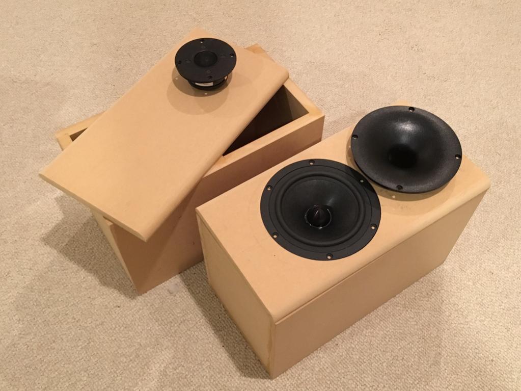
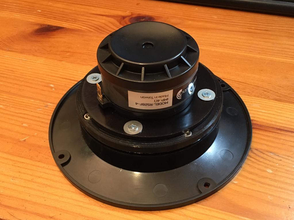
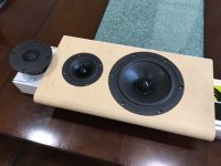
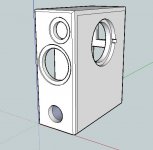
I have build a speaker for that Job that pulls together what I liked best in technical terms about the SLS S8R Monitor, the Dynaudio BM15 Studio Monitor and the Sonus Faber Extrema.

I also wanted an "average" Phonostage, now I might be doing the AA Phono a disservice by calling it average, but in many ways it a simple, workman like design, with decent sonics.

Digging around in my fundus of stuff saved for future projects, samples, leftover parts from modification work and so on I had all I needed.

I'll list details about the practical implementation in another e-mail (it is likely quite interesting), short and sweet, while working up a list of the parts I did not readily have (mainly resistors) to pick them up from the local Maplin (sorta like Radioshack UK) I got to think if I had learned anything since the original AA Phono that could be easily applied.

In addition I wanted a simple AC powered solution and I wanted to pick up on some comments that have rolled in since and various discussions and debates since.

So (drumroll), may I introduce to the genteele reader

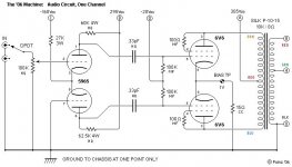
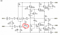
"THE ANALOGUE ADDICTS PHONO STAGE 2006 EDITION"

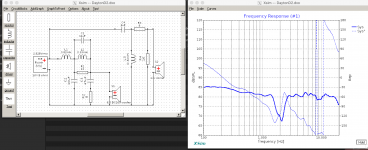
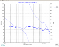
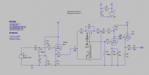
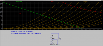
Here the signal circuit schematic:

An externally hosted image should be here but it was not working when we last tested it.


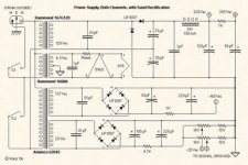
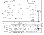
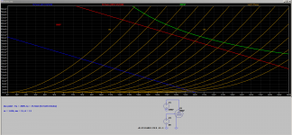
To go with this the powersupply:

An externally hosted image should be here but it was not working when we last tested it.


I'll discuss the differences and my implementation more detail later.

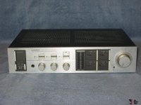
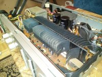
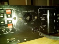
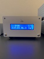
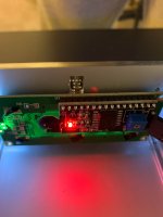
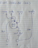
For the case I used once salvaged from an ancient, but very well build Hayes modem like this:

An externally hosted image should be here but it was not working when we last tested it.


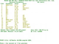
The power supply is another IT Services throwout and once supplied a small HP Jinkjet Printer with 30V/400mA DC, I downgraded this unit to an AC only.

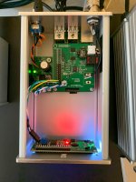
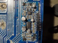
Finally, I have quite a number of Preamp Boards from the Shanling SP-80 Monoblocks which I tend to pull out like rotten teeth during mods. As these have space for four regulators, various rectifiers, capacitors and two Op-Amp's (with the PCB Patters alread offering an OPA627 option) and enough space and holes for the pre-pre section in the place that houses the PGA2311 volume control....

An externally hosted image should be here but it was not working when we last tested it.


An externally hosted image should be here but it was not working when we last tested it.


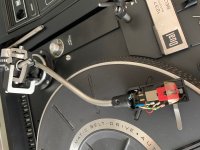
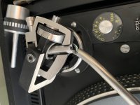
I'd show some photos of the implementation, but it's not overly neat.

I encountered one key problem, as originally the case was not screened (alu parts not connected to ground) the MC setting especially tented to pick up noise. I solved this by using screened wiring for the inputs and thereabouts and I also found a way to connect the Alu case sleeve to the screen. There is still some slight sensitivity to external hum fields, but it's now okay enough.

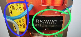
I fitted captive leadouts for the line out and jacks for the inputs. Parts quality is noted on the schematics.

More another day.

Sayonara

500 ohm output?

Hi! I have a Wurlitzer 1400 Jukebox which uses a 514 tube amplifier. In addition to driving the internal 8ohm speaker, there is also a two-screw terminal strip to allow connection of external speakers. This output is labeled “Aux Speakers 500 ohm Line”. There is also a “fader” rotary switch that the manual explains allows the output to be balanced between the internal and aux speakers. The manual explains that the aux speakers should use line transformers to convert from the 500ohms to the individual speaker impedance.

I know that there are constant voltage speakers that are typically rated at 25, 70.7, or 100 volts. But there is no reference in the manual to constant voltage or any of these voltage levels. Does the 500 ohms imply one of these voltages, or is the 500 ohm output something completely different? I can find a lot of info about constant voltage speakers, but no references to 500 ohm outputs.

Thanks for any help!
-Steve.

Potting transformers

I have seen many designs that show potted transformers and have often wondered if their is any sonic benefit to doing it or was it just to make a unit appear more pleasing to the wife/girlfriend. In any case can someone go thru the proper procedure for potting one's own transformers? What is used for potting material? Geez this is starting to sound like a gardening post. At any rate... any information will be appreciated as usual.

Thanks
Joe

Wayne J Dayton 2's crossover in Xsim

So a blast from the past here.. I had to use the wayback machine to get the schematic and writeup:
The Dayton II Project

The writeup specifically calls out using a 2nd order high pass and tweeter with positive polarity, vs testing with a 3rd order and inverted polarity. The thing is, when I model it, nothing seems quite 'right' which might be from drivers and spec data files changing with time? You can see in the attached images the original crossover, my Xsim version of it, and the poor results from the sim. Inverting the tweeter does improve things, but is also not great. (also pictured)

I can obviously tweak this to get different results, but the drivers I have ARE from many years ago and possibly different and better matching the measured results at the wayback link? Or did I make a mistake anyone can spot with the schematic in Xsim ?

Attachments

  • Screen Shot 2020-05-20 at 11.02.49 PM.png
    Screen Shot 2020-05-20 at 11.02.49 PM.png
    243 KB · Views: 124
  • d2xover.gif
    d2xover.gif
    31.1 KB · Views: 122
  • Screen Shot 2020-05-20 at 11.10.51 PM.png
    Screen Shot 2020-05-20 at 11.10.51 PM.png
    88.1 KB · Views: 111

FS: Nice front panel for RPI streamer

I have a nice front panel from FPE. It was made for use with a Raspberry PI based streamer.... unfortunately the cavity on the inside does not fit the VFD I am planning on using.

The panel is 4mm thick.
On the rear side, there is a cavity behind the "Pi" symbol for inserting a IR receiver if wanted.

The panel costs around $65, I will sell it as-is with the LCD and backpack inside for $25 shipped in the US.
It fits Hammond series 1455 cases, which come in varying depths that can fit a Pi project (see pictures for an example)

In my project I used a Digi+ and put a BNC on the rear panel, but you can use a DAC module and put 2 analog RCA's for a complete streamer.

P.S. There are 4 threaded holes on the inside for mounting the LCD. 2 diagonal ones have perfect alignment with standard LCD's, while 2 are offset and cannot be used. None of this really matters as the LCD fits snug in the cavity and does not actually need any screws at all for a secure fit

Attachments

  • 2020-05-20 16.35.20.jpg
    2020-05-20 16.35.20.jpg
    81.2 KB · Views: 307
  • 2020-05-20 16.35.01.jpg
    2020-05-20 16.35.01.jpg
    212 KB · Views: 323
  • 2020-05-20 16.35.48.jpg
    2020-05-20 16.35.48.jpg
    125.2 KB · Views: 307

How can i do v-cut and stam-hole in proteus ?

Hello everyone
I wanted to make pc to a factory in china but they send this messages and made me money refund.
How can i do v-cut and stam-hole in proteus ?
Best regards.

Attachments

  • Screenshot_20200502-121309_Chrome.jpg
    Screenshot_20200502-121309_Chrome.jpg
    340.2 KB · Views: 185
  • Screenshot_20200502-121300_Chrome.jpg
    Screenshot_20200502-121300_Chrome.jpg
    345.3 KB · Views: 194
  • Screenshot_20200502-121253_Chrome.jpg
    Screenshot_20200502-121253_Chrome.jpg
    333.8 KB · Views: 173

STM 32 F4 Discovery and Audioweaver, anyone tried?

Audio weaver supports the cheap STM32 F4 Discovery.
Audio Weaver® - the Only Cross-Platform Audio Design Platform | DSP Concepts
STM32F4DISCOVERY Discovery kit with STM32F407VG MCU - STMicroelectronics

Has anybody tried it out as crossover or FIR filter?

As mentioned in other post:
http://www.diyaudio.com/forums/digital-line-level/195791-open-source-dsp-xos-68.html#post4248409
You need extra ADC or SPDIF in as the card only has mems mic and I2S in.
But in principle one could make a very cheap FIR filter for bass correction or I2S digital 2 way crossover.
I guess with clever downsampling the 12-bit, 2.4 MSPS A/D converters also could be used for audiosignals with only a AFE added. (Especially for bass applications)
SR 2 400 000 Hz
n 10
SR/(2^n) 2343,75 Hz
So about 22 bits at 2k SR.

I know the audio weaver software is very powerful and has quite OK learning curve.

The STM32F407 is 32-bit ARM Cortex-M4F. The F meaning it has extended DSP instructions
http://www.dspconcepts.com/sites/default/files/white-papers/STM32Journal_DSPC.pdf

Regards Torgeir

Poindexter Musical Machine Build: power supply

I am new to builds but have begun the Poindexter 6v6 Musical Machine. Very basic question: How does one connect the Power supply to 2 audio channels?? The schematics show power supply connections to only one channel. Thanks so much for any help.

Attachments

  • Audio circuit 2006.jpg
    Audio circuit 2006.jpg
    49 KB · Views: 485
  • Power circuit 2006.jpg
    Power circuit 2006.jpg
    22.2 KB · Views: 477

PPI 2050AM doesn’t pass audio

Amp has good rails and +/-15v for the opamps is also good. Output stage has a few mv of offset, not objectionable. No output though. Probed around on the TL074 and LM833 hoping they were part of the preamp, but found no signal anywhere when the amp is fed a sine wave. Do these have mute circuits? If not, I’ll need a schematic to chase down where I’m losing the signal. Thanks in advance!

Enclosure design - Exactly what is required?

Hi all and preemptively thanks for all your help!

So I'm dipping my toe into the world of speaker design. I've ordered some books and got a few papers ready to read but in the background I was just hoping to ask some questions here to supplement.

I personally believe most things are easy when broken down into small chunks, I'm an engineer in the aerospace industry and while nobody knows everything about a whole engine, its too complicated, people learn to design small parts of a large assembly and you dont really need to know that much at all in the grand scheme of things.

So the first 'chunk' I wanted to delve into was the enclosure design, as being a mechanical engineer this is the bit I feel most comfortable with.

So my question is really, what is the list of requirements for a cabinet?

So my understanding is as follows:

  • High stiffness - which would be a material with a high Young's modulus and a structure with high 2nd moment of area (or something like that)
  • High damping - the speed in which vibrations in the structure decay in this instance.
  • Low internal reflectivity - which I think is to do with the ratio of acoustic impedances
  • The shape of enclosure itself - this seems to me where it gets difficult, the others are all relatively straightforward. I understand you dont want straight edges in order to remove internal reflections. But say if the nautilus shape is idea, why doesn't everyone use it?
  • Internal pressure - it would seem to me the ideal internal pressure (x area of the driver) would match the force required to overcome the resistive forces of the driver itself minus the force the driver can create itself. Or more realistically isobaric.

I haven't done any dynamics since university so I'm a bit rusty so sorry there's probably loads of mistakes in there.

Would people be able to list what they believe are the main requirements for an enclosure so I start evaluating the best compromises to make.

Class AB Amp Possibilities??

So I have built the Pass AB amp and am pleased with it. The problem is that I'm running maggies and can tell I need a little more power. Can I run a balanced signal +/- into the right and left of the amp input and pull my speaker output from the two positive outputs of the amp? Bridge them in this manner? If so I have other boards that I could build another unit and bridge it also. I understand the load issues that the amp will see and have to take that into consideration. Just thinking out loud.

Replacement Drivers for Height/Atmos

Hey guys. New poster here. Im trying to get some help with updating some old speakers on the cheap.

I know this is going to sound crazy but I think I need to replace my 4" drivers in my JBL n24's that Im using as height speakers. Yes, I said n24 LOL. I picked them many years ago thinking they would match fairly well with the tonality of my JBLS38's. These n24's are "breaking up" at volume which makes me think I need something to handle the power. If I run the same height signal to one of my mains, the sound does not distort. The n24 are only rated to 100 watts. Im thinking I need something better than 150 watts. I tried a speaker rated at 125 but still experienced the distortion. (less at the same receiver volume but still there). Can I get a 4" driver to bring the power rating up of these little speakers? This is a budget system so purchasing SVS, Klipsch, or other purpose made height speaker is not an option.

This is about the only one I could find in a higher wattage.

https://www.parts-express.com/morel-...-ohms--297-002

Thanks

SEAS tweeters Acoustic Energy AE1 Series 11

Not sure if I am in the right place for this! I have a pair of Acoustic Energy AE1 speakers fitted 25 TAFC/W-AE H 617 tweeters which are open circuit. I have carefully dismantled them but cannot see an obvious break in the wire.
Can you obtain replacement diaphragm/ coil assemblies ? Alternatively can they be repaired - if so can anyone in the uk help. If anyone has a pair of SH tweeters please let me know asking price!!

Trying to ID this capacitor

Hi all. Could I please get your help to identify this capacitor type (per attached photo)? I can't find this form factor on any of the color-code charts.

I'm assuming it's a high-voltage poly or maybe paper? It's one of several used as a decoupling cap in a little console tube amp from around 1960, built in Australia (I think). They are all the same color scheme with no other markings. Photo is of the one that looked cleanest!

A couple of these caps show cracks so I'll replace them all. I intend to measure them as I remove them, but any help to find a relevant chart to decode these guys would be appreciated in case they don't measure accurately.

The circuit uses a 12AX7 and 6GW8 (single ended) so I'm trying to dredge up a schematic that might be similar. Based on context, I'm assuming 400/630V rating and a value between about .001 and .1 or thereabouts.

Attachments

  • mystery cap.jpg
    mystery cap.jpg
    382.8 KB · Views: 104

Mark Audio/Fostex... what to choose for new speakers

Hello,
after a friend visited my and listened to my MKII with Fostex 167E he directly offered me to buy them from me... I never thought to sell them, but since my little daughter (10 months old) likes to touch the drivers, and I will not easilly find a replacement, I do play with the idea, to give the speakers away as long as the drivers are not damaged...
So what now, ... I think to build a new couple of speakers, they should outperform the MKII, I was looking a little around, and SEAS exotic, Lowther and Supravox are out of my budget, so I have now two possible manufacturers, Fostex I can say that my current speakers in Bob´s desing are awesome.
Or Mark Audio, that caught my eye for some time already. Tang Band I cancelled from my list...

what would be our opinion? Im looking for a speaker that will have a clarity of the 167E, deliver more bass and top end and overall more detail (althout that is not a easy task)
I play with the idea for the following drivers:

Markaudio Alpair 10.2
Markaudio Alpair 12
Fostex F200A
Fostex FF225WK

The F200A might be the champ, but I´m not certain whether he is as well not out of my budget...

What would be you oppinion?
Any experience with the Alpairs? How much detail do they deliver, when the sensitivity lies below 90 Db?

LIFEPO 26650 3200mAh (for Ian supply), LOK silver spade, Furutech fuses

New newer used, excellent accus LIFEPO4 size 26650 capacity 3200mAh for Ian Battery supply or your own project.
I can also be used for direct supply for dac and other digital parts. No need for any regulator.
For now 10pcs for sale.

Price 5€-1 piece if you order 10pcs
6€-1 piece at single order

Also for sale 8pcs silver plated LOK spades for speaker cable termination.
Screw type no need for soldering
Price 4€ per piece. In set are 8pcs.

Furutech-padis silver fuses 5x20....T6,3A
Price 15€ per piece

Attachments

  • Lifepo.jpeg
    Lifepo.jpeg
    279 KB · Views: 278
  • Lifepo1.jpg
    Lifepo1.jpg
    115 KB · Views: 267
  • lok.jpg
    lok.jpg
    69.6 KB · Views: 264
  • furutech.jpg
    furutech.jpg
    7.3 KB · Views: 268

FS: AudioTechnology 10C77-25-10-SD-KAP + 18H52-06-13-SDKT-WR

Hello.
Its my sad duty to put on sale my beloved Audiotechnology 10C77-25-10-SD-KAP and 18H52-06-13-SDKT-WR

The 18H52 features a titanium voice coil custom made for them and installed in Audiotechnology factory. They are really unique drivers.
The 10C77 are sandwich cone version.
Attached you will find proper TS parameters measured at AudioTechnology factory.

They are really misused because they might have less than 20 hours of playing and no more. I build a nice 3 Way active floorstanders that I couldn't really enjoy and now I need to leave them.
I'm moving and I have to sell my system and reconfigure everything (life, Audio and everything).
Because it will be very difficult to sell the floorstandes itself, i would sell drivers alone.

Regular price for 18H52 (not this titanium VC version) is 275 euro each (550 pair), this version with Titanium Voice coil was 720 euro pair. I’m selling the pair for 450€

Regular price for 10C77 is 695 euro each (1390 pair). I’m selling the pair for 1000€

Not included shipping or ebay fees if apply
I'm based in Malaga (Spain) Please, ask for shipping quotation.
I do have original boxes all of them.


is it okay to ugrade internal wires, binding posts without changing the crossover?

Hello,
Based on some experience with Ikea furniture I have decided to buy the LS3/5A loudspeaker kit from Falcon Acoustics. It is a fun a first project, but I have to say it is more difficult to build it than an Ikea furniture...

I have a naive question:

The speaker kit comes with good quality, buy relatively simple speaker terminals and OFC copper cables. I'm thinking to use better WBT binding posts and silver cables instead.
The additional cost is not that much considering as it is a small speaker.

Does it require to change the crossover when upgrading the internal wiring and/or speaker terminals? (if yes, then I'll probably drop the idea for now)

Help identifying where to tap for pre-outs on Technics 2 channel receiver

Hi all, I know this is fairly simple one for the experts so hopefully someone would be willing to help me locate where to tap into for some pre-outs. I've had this 1991 Technics SA-GX303 since new and I for whatever reason, it just has a really great sound to it and would like to continue using it but need a sub feed.

Anyway, I have the service manual but I'm not educated enough to know where I should tap into for a pre-out to feed a sub. Any help would be greatly appreciated. Thanks!

SM is here:
Technics-SAGX-303-Service-Manual.pdf - Google Drive

Tuning the Qtc in an aperiodic bass by changingthe stuffing

Hi,

My understanding is a sealed cabinet with a Qtc equal or above to 0.8 can lowish its -F3 by increasing the sealed volume. I assume so it's increasing the Qtc, the stifness of the curve below the -F3 and of course the timing factor towards less ideal behavior as less flat low end... anyway the room also adds is own gain.

Assuming it's about tunning an already made sealed box that has already no stuffing but the minimum felt on the walls, can we assume than foaming or stuffing with wool the enclosure will increase the virtual volume seen by the driver and so lowish the -F3 and increase the Qtc ?

What if about the front open load of an aperiodic design : can we also tune the port load chamber in front of the speaker(s) this time to acheive maybe a similar result with less : one can increase the volume up to 20% theorically with full stuffing on a given sealed enclosure volume but we can also play to decrease the volume by putting in it another volume like a brick, bag of sand, sealed bottle...

I surmise it may also move the electrical resonance frequency and the resonance mechanical frequency of the box as well.

How will you process wanting to redue the -F3 by -5 dB for instance with this aperiodic sealed bass cabinet scenario please ? Does such tunning move the band pass widthness of the spl curve and also moves the +F3 according to you ?

sony speakers 1-504-664-11

Today I fried a tweeter in one of my Sony SS-X7 speakers. It was stupid acting with provisional connectors and my prototype amp that somehow caused extreme noise that made my tweeter die.

I don't know whether Sony will support me and sell me a new tweeter for replacement.

On the backside the tweeter reads:
SONY 1-504-664-11
H 720-6ohm
Made in Norway 24/00

Do you have an idea where to get such a tweeter?

Does anyone recognize this tweeter as a brand X model Y one?

Cone diameter is 1 inch (~25mm).
Magnet has 72mm diameter.
Inner screw mounting diameter is 50mm.
Outer mounting screw diameter is approx 94mm.

I liked the sound of the speakers very much.

Does someone know an alternative to use for the case I can't manage to find the original part?

Thanks

problem with tube preamp after output was connected to input

In an accident during a testing session of equipment my cheap chinese preamp had the output connected to the input for a very short time. Now the preamp does not give a lot of signal anymore. When i open the volume maximum there is still a bit signal, clean sounding (not distorted), but very weak. it!s point to point build and used to sound suprisingly good when i bought it so i would like to get it working again. If not possible, i'll do the original plan and use the enclosure with connectors and transformers for an own build (it was that cheap that it was cheaper than buying the parts seperate).

Inside nothing looks broken, no smoke or burning smell was seen during the accident. I tried to replace the tubes, but that does not make a difference. All tubes also look ok, and work in an other device without issue after being in this device. I think it also emits dc on the outpot (i used it with a solid state amp with dc blocking caps on the input to test). Could it be that the output coupling cap is gone? I don't really have test equipment to test it for the moment but a simple multimeter.

Included is the schematic and a picture of the inside in actual state. The tape thing on the side is because i modded the transformer setting from 110V to 220V and needed to fix the cables (i did not want to cut them of)

Attachments

  • 禾田茂电路图.png
    禾田茂电路图.png
    43.4 KB · Views: 217
  • IMG_1968[1].jpg
    IMG_1968[1].jpg
    985 KB · Views: 208

Behringer b3031a auto power on mod?

Hello everyone,
this is my first post here, I'm sorrry to start with a question but I'll try anyway 🙂

The auto power on circuit on these monitors (pretty decent for the price if you ask me), is triggered only when a loud signal is received. So speakers shut down on the quieter passages or if you are listening at low volume.

I'm aware of the Elliot's auto power on circuit (Project 38) and it will be my last restort if I won't be able to modify the circuit.
This is the only schematic I found and it's from the b2031a model but it should be similar
Behringer B2031 Schematic audio, Service Manual, Repair Schematics (I hope it's ok to post this link).
The auto poweron switch is on the top-right area of the schematic.

There are 2 VRs in the schematic but I doubt they have anything to do with the auto-poweron (maybe it's the bias?).

I already have some experience building DIY projects (the bigger one was a 18W guitar tube amp, ampmaker pp-18), but understanding this schematic is way beyon my knowledge.

It would be great if someone could shed some light on this, I'm sure all it needs is changing a couple of resistors! Thanks a lot for your help!!!

Cheers, Luca

Crown CTs2000 and Cts3000 channel 2 clipping on idle

I have 2 amps CTS 3000/2000 that came for repair. The 3000 had a blown smps which I manage to fix finding a couple of vias raised and burnt links and the crowbar scr blown. Connecting the amp to the power source with a current limiter (heating element) the amp came on but channel two started to indicate that there was a signal on the input. Checking the output with a scope I found out that an irregular oscillation was coming out of channel 2. After a short while (5sec) the clipping indicator lights up and the output dies.
Checking the gate drives these where both good and I also interchanged them and the fault still persists on channel 2. I also interchanged the the other two modules which when fitted on the good channel both worked good. I have a schematic which I downloaded. I tried to follow around but could not find anything faulty. The amp was fully dismantled and cleaned and also checked what I could for any apparent fault but could not find any.
Has anyone found a similar fault maybe he or she could highlight me where to look for such a fault? I spent hours looking around and did not come to any conclusion yet.
Is there any service manual available? or maybe a repair guide?

PCL82/ECL82 SE PCB design - thoughts?

I'm planning on making a simple, compact SE PCL82 amp for the kitchen / office. For ease and speed I'll get some PCBs made up using PCBway (10 for $5).

Attached is my attempt at a design featuring:

- pads for GNFB
- pads for shunt (plate to plate / Schade) feedback
- driver stage bias by trim pot or LED
- pads to allow both triode and pentode connected power stage
- alternate B+ chain
- plenty of test points
- should be usable for both ECL82 & PCL82

Initial component values are shown on the schematic (based on PCL82 measured curves taken with a uTracer). I'll have plenty of scope to tweak on test.

The HT and heater supply will come from one of Merlin's regulated power supply boards. OT are old, tiny ones from eBay. PS is a custom toroidy.pl left over from another build.

The kitchen amp will use two boards for stereo, the PS board and an additional PS relay board (to be designed) to give a 5V supply and control the overall power state via a Raspberry Pi Zero.

I hope to use one of the extra boards as a test bed to have a go at tuning the GNFB / square wave response / Schade etc etc.

Can anyone see any issues?

Tristan

Attachments

  • PCL82_schematic.png
    PCL82_schematic.png
    194.2 KB · Views: 1,852
  • PCL82_PCB.png
    PCL82_PCB.png
    178.7 KB · Views: 1,441
  • PCL82-Triode.png
    PCL82-Triode.png
    106.5 KB · Views: 1,200
  • PCL82-Pentode-triode_connected.png
    PCL82-Pentode-triode_connected.png
    139.6 KB · Views: 1,333

FS F6 amplifier

For Sale F6 DIY Amplifier
Got too much stuff and need to get rid of some of it. I have a F6 amp that I have built in a Perreaux amplifier chassis that works great. Asking $300 us which doesn’t cover parts cost buyer pays shipping cost unit weighs around 40 pounds and box would need to be approx. 24in X 24in X 9 or 10 in.
In the past I have run the amp with various single driver speakers and it is an excellent match for speakers at 87db or more, not so much for my Magnepan 1.7. I only have a couple of requests if you purchase it 1. Do not short the outputs, 2. You can pull the top off in fact I recommend, it but please do not adjust the bias and offset until you are satisfied the amplifier works, after that it is yours to do as you wish, as this is DIY. I have used the chassis and transformer for a 200 watt BA2 so the chassis is very versatile and would work for F6 or other Pass amps. The transformer is ANtek 4438 and connected with 240 input wiring to half the 38v/38v windings for the F6. Any questions or for pictures P.M. me.

Active Bax Preamp - review request

I'm looking to build a valve preamp to go in front of a DCPP:

* source selection (DAC, valve phono, line level RCAs)
* volume control (stepped attenuator)
- balance
- tone control (Baxandall)

The 1st two are handled by an available passive module. The output of the module would then flow in to the active section. I concocted this from Merlin's new book and Max Robinson / RCA manual.

The input stage is a fixed bias cathode follower using 1/2 a 12AU7.

The tone stack is an active Baxandall with feedback from the 2nd 12AT7 stage. I included R1 = 22k to keep the output close to 0dB when the controls are at mid points. The output comes from a 12AT7 CF.

Other than wanting to know if this looks a sensible approach, I have the following questions:

1) Is it possible to get, say, 3-6dB gain through the circuit to allow for quieter sources / losses due to attenuator or balance control?
2) Where would a balance control go? (ideally one using a single gang pot in an active fashion)

For (1) I thought of bootstrapping the 2nd stage, but I think that messes the feedback.
For (2) I had hoped I could use the bottom of C16 through a pot to the grounded wiper (with the other channel coming in the other side), but that doesn't seem to work (only giving 0.5dB reduction).

Many thanks,

Tristan

Attachments

  • ActiveBaxPre.png
    ActiveBaxPre.png
    52.1 KB · Views: 536
  • ActiveBaxPre-response.png
    ActiveBaxPre-response.png
    63.6 KB · Views: 519

Quick Dynaco A25 Crossover Advice Needed

Looking for a little guidance trying to resurrect an old pair of Dynaco A25s. These appear to be an intermediate model, ferrite 25F-EW woofer but with the 1.5” H087 tweeter, date on tweeter indicates 1976. These are beat to hell and been in storage for last 25 years, ridden hard and put away wet, but there’s enough there to save. I’d feel bad not trying. One speaker’s intact, other has a badly ripped cone and a dead tweeter. I patched up the cone pretty well, till I find replacement, and found and am waiting on an old H087 from eBay. Speakers belong to a cousin and come paired with a lovely Nikko TRM600 that’s in clean shape and I got running after a spell on a Dim Bulb Limiter and quite a bit of Deoxit.

This A25 pair seems unique, for the XO there’s pot instead of the switch with the resistors. Pot is 50R Linear with a 2.5uF capacitor, pot is set up as a divider, if I understand correctly it’s an L-Pad and same as the more typical resistors and switch set up of 10R and 5X 2.2R. Both pots are completely trashed so I can’t get a reading off them to figure out what the series and parallel resisters would be for flat/normal which should be with the pot centred seeing it's linear. Speakers are all original, I’m the first person to ever crack them open.

I want to replace the pot and cap with a simple in series cap and resistor to give flat response. The cap seems a little weird as it’s very low at 2.5uF instead of the typical 5uF or even 8uF usually seen. Maybe this change was made to accommodate the then new ferrite woofer which from reading on the web had slightly different characteristics than the alnico. Right now I’m running them with 3.3uF / 10R I luckily had in my parts box. I used that combo as it’s what SEAS uses for their A26 kit but I really doubt their modern drivers are exactly like the old Dynacos, or my oddball Dynacos.

Early test sounds pretty good, these have a lot of bass though pretty one note, sounds like college 1978! Hard to judge with one tweeter still out, but tweeter seems a touch forward, bit detached, could be just a bit more integrated.

I need to order up the resistors, caps, and binding posts so any advice how to set these up for flat given the below drawing would be much appreciated. I figure best to set them up as they were originally designed and tweak from there if necessary. I’d prefer to ditch the L-Pad resistor combo for just a single resistor in line with the cap, unless that’s a bad idea. Much appreciate any guidance.

Attachments

  • Dyna A25 XO 25FEW & 087.jpg
    Dyna A25 XO 25FEW & 087.jpg
    346 KB · Views: 291

  • Locked
Wire types for internal wiring??

Hello,

What are the best types of wire to use internally, for woofer/mid/tweeter?
In other words, what gauge and construction for which purpose?

I used to use whatever speaker wire I would use from amp to speaker to each driver, but recently it was mentioned that it's preferable to use wire types which are suited to each driver to achieve a specific purpose..
IE: solid core is best for bass... a thin gauge might be used to drop a slightly loud tweeter rather than add a resistor, or, litz/braid/flat is better for something.... etc. etc.

BTW:
No offence intended... but to those who will almost inevitably chime in to say it all sounds the same and it doesn't make any difference... please refrain from posting.
We've all heard alllllll those arguments, and obviously don't agree with them if we're posting/reading/replying to this..
It gets tedious..... 😛

Thanks in advance!

American manufactured vacuum tubes

I have a tube preamp that is a prefab kit-type manufactured in China somewhere. It runs on one 6Z5P as a rectifier then to three 12AX7B's, all Chinese tubes. I would love to install 12AX7A's to replace them with an American made matched trio. Does anyone have experience with this open faced (no enclosure) pre-amp? It has four Inputs, one Left & one Right Outputs on the back, & a Volume knob & a Source Selector knob on the front on a wooden edged and stainless steel box.
Who makes good 12AX7A's??? American companies?


Let me know...

Sub box pro reliable?

I’m planning on making a ported sub box for my 2 12” DB drive SPW DVC subs. They are 600rms each. I have looked all over to find a prefabbed box that will fit in my camaro but it is hopeless lol. Only 1 I have found and it is tuned too high for what I want. I bought a sealed setup but they aren’t cutting it. Need ported.
I have designed a box on sub box pro that I think will work as long as the program is correct. 30w by 14h by 16 deep. 6” aero port. 18” long. Tuning goal was 35hz. It is the sky high adjustable one. Has anyone used that program before and had good success? My current amp is a pioneer 800rms at 1 ohm. I relize it is a bit low for those but wanted to try it out and go from there. I am using a line out converter. Any input is much appreciated. Will be my first attempt at a box.

tse ii driver tube rolling

Has anyone played with the 5842/417a on their tse? I had originally been running a set of amperex tubes and just a few days ago picked up some WE 417a.

Everything I had read said the WE tubes should have been a big improvement over the Amperex but Im not quite so sure. Is it just a matter of the tse not being overly sensitive to tube changes or did I just get a bad pair of tubes?
They sound fine but no huge, or really any at all, improvement over the old tubes I had been running.

Has anyone else played with different driver tubes and had similar or different experiences?

Prepping to celebrate the National day!

Not sure where to put this, but decided on the Lounge.

Planning to take my new speaker boxes out on the terrace tomorrow, 17th of may is our National day.
And it's really weird that we're supposed to keep distance and stuff like that, so I'm planning to make up for it by putting my setup outside and blast out our National Anthem "Ja, vi elsker (dette landet)" (Yes, we love (this country)) so the whole neighbourhood get's the idea.
Normally all the kids would march on the streets together with marching bands and all the grownups would stand along the sidewalks to cheer them along, afterwards it's tradition (at least for me) to give the kids whatever food they want all day, there is no limit to ice-cream, waffles, cake, hot-dogs, spare ribs or anything else they want. Only hard rule we have is to have a breakfast together with smoked salmon and scrambled eggs.

The city I come from (Aalesund, tried to write the a with the circle over it, but lots of weird symbols came on the preview 🙁) is about 500km away, and although the celebration revolves around the same things like kids having fun, traditional "contests" like the bag races, potato or egg race, lotteries and stuff like that. It could not be more different, in Aalesund every year I would happily be awakened around 07:00-08:00 sometime because a marching band was making noise outside, there was tradition for a specific circus to be there at that day so we had elephants in the streets together with jugglers, clowns and acrobats. So much fun, no stress, everyone has a good time. That time is never coming back, and the place we live now is very quiet. A few years ago we woke up because one of the "Russ" cars was driving around the neighbourhood blasting out a techno variant of the national theme at 07:00 in the morning, that made me so happy because there's never any noise here.

I've been to Oslo a few times to celebrate the day, and it's very "pretty" would be the best way to describe it. I do think it's more stressful and expensive than I like, so the celebration is better enjoyed in a small town IMO, it is a much "closer" (regardless if you know anyone) and enjoyable experience.

Really looking forward to the celebration, but the circumstances makes it very weird.

Strongly considering splurging on a recording (by 2L studio) in 24bit/352.8khz by Forsvarets stabsmusikkorps (Staff Band of the Norwegian Armed Forces). I am never going to be able to hear the difference between the 96khz one and the 352.8khz one, but somehow I feel that the National anthem deserves and demands a bigger space on my harddrive.

So I guess that sums it up, and it seems like I probably just convinced myself to get the huge file-format despite being completely unable to discern any kind of difference in quality... 😀

Here it is on hdtracks in case anyone's interested.
HDtracks

It's the best national anthem of all! 😀

(This post might contain some infinitesimally biased opinions)

Anyone else preparing/having a celebration that they want to brag about are very welcome to do just that. 🙂
All positive vibes and national anthems are welcome!

How to recognize a broken OT?

I took over a Mesa Boogie Fifty / Fity tube amplifier.
This is a stereo tube power amplifier.
However, channel B has a problem (which I knew when purchasing). I will quote a piece from the seller:
"2 years ago a transformer and a tube broke. I then had this checked at NEL (a local fix) and had a new tube inserted. Since I still play mono, I decided not to use the broken transformer. According to the manual, the poweramp can remain perfectly 'on one leg', as long as you turn the volume knob of the unused channel closed. "

I then asked the seller what caused the output transformer to be killed and whether all the tubes were replaced. To this I got the following answer:

"Indeed, an output transformer. There is still sound coming out, only very weak. Earlier whisper level. No idea, at NEL they said it could have multiple causes. One of the four lamps was cracked so that pair was taken out and replaced by a new pair. Channel B now has the old lamps. Channel A new. Furthermore, they have (if I remember correctly) also replaced some diodes and capacitors. There is nothing wrong with that. "

I do not have the amplifier yet, but it should be sent today.
I can order a new OT from TAD but I first want to know whether it is / cannot be something else.
Before I am already gaining information.

Here I have some questions:
- If an OT is broken, does any sound come out at all? Although the volume is very low.
- Is it plausible that an OT is broken. Or is it better to look into surrounding components? Or perhaps solder joints.
- Is there an easy way to measure or check an OT?

Unison smart 845 modifications

Hi,
I have bought two Old unison smart 845
I see that the scheme is quite simple and components not very high-end.
Somebody can tell me which modifications can be applied.
I was thinking to reduce feedback, change coupling condensator, but more than that i cannot do.
I am quite good in electronic DIY, but lack knowledge.
I think that power supply can be well upgraded.

Thanks for help

Wire specs - dummy load

I'm in the process of building a switchable, 4/8 ohm, dummy load device for use in testing audio equipment. My immediate need is to test a set of tube, mono blocks each outputting around 50 watts (20 v into 8 ohm, like 3 amps); but I think I should build the device to accommodate larger units: say tube amps up to 150 watts and SS up to 200 watts.

I have two pairs of 8 ohm and 4 ohm, 100 watt, dummy load type resistors, but I would appreciate advice on what size hook-up wire to use. (I've got some 22 AWG, 600V wire on hand, but I hate to use it up if it would be over-kill.

Thanks.

Dayton Audio DSPB Series Active Crossovers Quality

I'm wondering if anyone has used or heard speakers made with the Dayton DSPB Series electronics as a DSP crossover and if so, how's the sound quality on them, both the options with and without included amplification.

I find the pricing to be very attractive - I've avoided going the DSP route in the past because it's been both more expensive than passive (at lower order XOs) and I don't have enough amplification channels. This product line seems to solve both of those issues, bringing the price basically to about the same level as passive with included amplification (DSPB-250 and KEB-100 for 3-way), or cheaper if you opt for no amplification (DSPB-K and DSPB-KE). I also love how flexible and easy to use it seems.

I hesitate to consider using these in a higher end speaker design though because at that price point I'm skeptical of the quality of the sound from the signal processing and amplification. Personally, I have difficulty hearing the difference between amps as long as one isn't absolute trash (don't think I could identify my class AB NAD C372 over my Onkyo receiver, which uses Op Amps, if using only amplification on each in an A/B test), but I've found that I'm pretty sensitive to different DACs.

So
1. How's the quality of the analog/digital conversion on this?
2. Is it worth using or should I really just go with minidsp or something else instead?
3. Are the amplification channels decent or do they fall into the trash category?

Any information is helpful 🙂

Thanks everyone!

SE amplifier design process

Hey guys. So as you already now I am new in the field and I decided to make the effort and actually go through the design process of SE amplifier. I know there is lots and lots and lots of schematics from experts, but by doing it yourself you are actually learning right?

Simple SE amplifier

I am going to use two double triodes: 6P3N as driver and 6P6N as an output tube. Since placing tubes in parallel should in theory decrease signal to noise ration, I am thinking of using both double triodes for one channel.


Results are obtained from simulated Anode curves


Driver stage

HT will be around 200V, so I am going to use Ra = 10K for 6N3P, this should give Qsc point of Va = 132V, Ia = 7mA (for one triode), if I am going to connect two triodes in parallel I expect that current will double. Is that correct?


MU is around 35 so with two triodes connected in the stage I expect resistance loaded Voltage gain to be around A=20. (Not sure that is enough?)

Also added grid stopper resistor of 1K - cut off freq. above 20kHz - is this value work ok?

Output stage

Maximum anode dissipation for 6n6P both triodes is 8W. Z(out) = 200^2/8 = 5K nearest standard output transformer value is 5.2K (there is a cheap option of 5VA, 5.2k, how do I calculate if VA rating is sufficient for an output transformer?). Do I need to use grid stopper in this stage also?


Qsc point of Va = 200V, Ia = 35.5mA (I am guessing for both triodes?) Mu is 15, so I expect with two triodes connected Voltage gain to be around A=13.


At this point I am trying to simulate stages and full amp with LTSpice


any suggestions, corrections, opinions, advice is very welcome and will be appreciated

Attachments

  • schematics.PNG
    schematics.PNG
    29.8 KB · Views: 494
  • 6N3P.PNG
    6N3P.PNG
    71.7 KB · Views: 484
  • 6N6P.PNG
    6N6P.PNG
    87.2 KB · Views: 481

Harmonics of the Human Cardiovascular System

I'm a college student who is studying to go into the medical profession. I was googling about looking for sources on damping factor, when I stumbled on this article.

Looks like in a parallel world they are talking about damping too... and they also have a (different) Dr. Geddes!

I stumbled upon this gem:
arterial%20waveform%20and%20component%20harmonics%20from%20Hansen%2C%201949.JPG

The original article is here. It's a fun read!

I really wonder what an audio amplifier would sound like with a distortion characteristic similar to the human cardiovascular system. :magnify:

TU-8500 really bassy, probably Rega turntable

I finished assembling my TU-8500. I also got a used Rega P25 with Black Pearl cartridge. The Rega is going into the Phono Pre Amp on the TU-5800 with MM selected. I also have an older Pioneer DP-29F (amazon).
That Pioneer has a phono-amp built in, so I can use Aux1, instead of the Phono-pre-amp, so I can easily do an A B test.


The Rega sounds bass heavy, totally lacking in the treble vs the Pioneer. I'm convinced something ain't right. It's also totally lacking in the treble vs the digital version. (Aux2 is a RaspberryPi with Allo BOSS DAC)


Any ideas? I probably only have 12-20 hours on the pre-amp. Factory tubes. I recall they were these JJ tubes. But I could be mistaken. I did purchase some other matched tubes (TS-12AU7 Tung-Sol 12AU7) that I haven't installed yet.


I need to get this turntable dialed in before the wife says "I told you so."
Help!


Grundig RPC 350 Arm Help

Can anyone help ? My pick up arm on my Grundig RPC 350 is broken, the thin metal tube snapped. I have a new one but need help in how to replace it, how to dismantle the old one to replace the tube on the arm. Please see images below. Need to know which screws to take out and how it comes apart. Thanks.

Attachments

  • IMG_5609.jpg
    IMG_5609.jpg
    702.8 KB · Views: 110
  • IMG_5610.jpg
    IMG_5610.jpg
    527.8 KB · Views: 111

JBL 2446H Measurement interp

For the last year or so I have been building a multi cell mid-bass horn, purchased two, used JBL 2446H drivers, along with putting together a measurement system. The horns are built, and have tested the JBL drivers
and have some data to post to inquire about interpreting some of the graphs. I have a fair driver knowledge, but lack the interpretation skills on the REW graphs

All the graphs are just the JBL driver alone, no horn. I used REW software, with a Mini DSP mic, the mic was positioned 2 inches away from the driver exit. Below are .jpeg graphs and data files

SPL + Phase
SPL + Phase.mdat
Impulse
Spectrograph
Waterfall
Impedance
Impedance.zma
Distortion

My concerns are the spectrograph and impulse graphs, along with the impedance graph with the large second spike at 1300 Hz, as this is in the mid-range being reproduced by .

Does the spectrograph look normal, or is that proof of a damaged diaphragm?

Does the Impulse file look normal, or does the graph show ringing ?

The Impedance rise at 1300Hz will need some suppression?

JBL 2446H Distortion - NO HORN.jpg

JBL 2446H Driver NO Horn Spectrogram.jpg

JBL 2446H Impulse NO HORN.jpg

JBL 2446H Waterfall NO HORN.jpg

JBL 2446h with Multicell horn Impedence 2.jpg


Mid-Bass horns built from this post:

Error 404 - Forum Page Missing cell-horn.html


Any help is appreciated,
Tom in Lafayette

Bicycle Speaker

I'd like some advice.
I am building a new portable bluetooth speaker for my bicycle.

I currently have a 4.7" hammond abs box with 2 monacor sph 30-4 drivers in it. It's fed by an amp6 (tripath TA202) powered by a 4 cell 12.8v LiFePO4 batttery.
Pros of current system: reasonably loud (guessing around 90dB), weighs less than 2#, small form factor, >5hr battery life at high volume.
Cons of current system: stereo sound from 2 drivers sharing same enclosure aint right..but honestly doesn't sound bad to my ears), lacks bass below 150Hz, no bluetooth and I go through a lot of lightning to 3.5mm jacks .

Ways I'd like to improve it: add bluetooth, new amp, new power supply, new drivers, new enclosure....maybe dsp to shape response in less than idea enclosure.

GOALS of new bike speaker: small size, low weight (<5#), more dB, lower bass response, longer battery life.

Current ideas:
-Amp: tpa3116 with bluetooth like a Dayton Audio KAB-250v3. no dsp but other goals met. could add a miniDSP, but would need a buck converter. I could use Dayton Audio DSPB-250 for the dsp and add Sure Electronics AA-AB41136 Bluetooth 4.0 Audio Receiver to get both bluetooth and dsp...but would like to power the amp with 22.2 volts...again necessitating a buck converter for the 12v bluetooth receiver. (extra space and weight)

-Battery: two Dayton Audio LBB-3 connected to a NTE R14-11D10-24 10A 24 VDC DPDT General Purpose Relay and 4 diodes to allow for playback AND charging without removing battery.
My current setup has amp, battery and speakers all in separate enclosures (works well for aerodynamics). I am not against using a similar 3 piece setup but also think it'd be nice to have all components in 1 enclosure to remove from bike and take it to the beach.

-Speaker Enclosure material: mdi and plywood are heavy. Considering using pvc or abs tube(s) or sheets. Tubes would be easier to work with (less edge glue failure potential).

-Speaker Enclosure : restricted by wanting small volume enclosure for mounting on bike. I want to get near 100dB and play from 80Hz - 20k Hz. I've read the boominator thread and understand getting below 80Hz outdoors in a smaller enclosure aint gonna happen. I also understand Hoffman's Iron Law...I'd just like to push that law as much as I can 🙂
Between handle bars above tire (preferred location). 13" x 8" max exterior size (10.7L total). Best idea I've had is using two 8"pvc pipes cut to 5.5" height (4.5L each before subtracting for driver basket(s), port(s), batteries, amp. I would seal off one end and mount speaker and pr both facing outward to allowed sealed ends to butt up against each other and have drivers firing towards sides of bike. side firing drivers allows me to crank up the volume without destroying my own hearing 🙂
Rear rack above tire (hate to add a rack and look like my grandpa doodling down the road). 17" x 11.5" x 6" max external size (19.2L total).

Enclosure type: Likely passive radiator as box likely too small for port...but love the low end extension I could get from a port. I DO NOT UNDERSTAND HOW 1ST PORT RESONANCE WOULD EFFECT A FULL RANGE DRIVER.
dayton ds90-pr seems to model well with most of the drivers I am looking at with a tuned volume of 1.25L for 82Hz fb.

_Speakers: must be efficient to preserve battery life and get near 100dB in enclosure. Would like a single full range driver per side to reduce weight and volume of enclosure. Would like to stay under 4 ohms for amp efficiency and subsequent battery life.
Potential candidates:
dayton nd91-4
dayton dma80-4
dayton tcp 115-4 (heavier)
peerless sLs-85s25cp04-04 (heavier)
faital pro 3fe25-4
faital pro 3fe22-4
fatal pro 3fe22-8 (two drivers per side to stay under 4ohms for efficiency)
peerless 830985
b&c 3.5ndf26 (two drivers per side to stay under 4ohms for efficiency)
lavoce fsn030.71 (two drivers per side to stay under 4ohms for efficiency)
dayton dc130b-4 (heavier)
morel caw 428 (likely require tweeter)
silver flute w14rc25-04 (heavier)
beam 4fr40nd (two drivers per side to stay under 4ohms for efficiency)
18sound 6nd430 (looks excellent, but would be too large and heavy with 4 drivers)
peerless ne180w-04 (heavier)
peerless ne123w-04

Apologies for most choices coming from parts express, but their selection of all components seems good. I use winISD pro to model. I do not own any audio measuring equipment.

ANY advice / wisdom / suggestions would be greatly appreciated. Thanks.

3way active mini towers help

Hi Guys ,
i am making a 3 way active mini tower with side firing subs , using drivers available locally here in india , I dont have the mic to get the frd files needed for them and only viable option currently is to spl trace the drivers can any one help me with the frd & Zma files, please find attached datasheets of the drivers and baffle dimensions & placements

Attachments

Rockola amplifier lacks treble.

Hi audio lovers ! I bought an amplifier from a Rockola 429, the chassis is 41056-A. The tubes I got with were very bad sounding so I got some new output tubes. The problems are the basic hum and the lack of treble. Even if I put the treble at maximum, it is still not enough compared to my other amps. Does someone have some advices for improving the sound, because right now my only option is to sell it. Maybe chage all the caps , they seem to be all original (1965). Or modify the circuit, or use all the transformers and tubes, get a modern schematic and redo it entirely.

Ohm Clone

Has anyone tried a full-range driver mounted upside down with a super tweeter ala the Ohm (Walsh) speakers? It doesn't appear that the ohm drivers are that special based on a casual inspection. Maybe that is why they go to such lengths to hide it in a canister under the top grille.

My idea is to try to clone the Ohm design with a full range driver (Audio Nirvana comes to mind) with an AMT tweeter crossed high around 8K. If it is a failure, I could just mount these drivers on an open baffle and still have good sound.

I like the Ohm sound but I think they are overpriced for the driver quality that you get. And the tweeter is weak IMO.

DIY Step Attenuator: Ground Woeees...

Hey All!

First post here, hope I am in the right place/category!

To tip my toes into the world of audio (coming more from the digital design/embedded systems side of things) I wanted to design a relay step attenuator to sit between dac and amp in my schiit stack 🙂

I have gotten the first PCB revision in and the 127 step attenuator works great.

I am however having a little grounding issue.

I have attached the schematic.

In my design the audio path and digital side of things are fully electrically isolated (relays). Audio side is fully passive (ofc) and the digital side of things is powered from a 9v AC mains transformer/adapter.

My setup right now:

(schiit stack is at home, I am stuck at my parent's ... corona...)

My phone (floating ofc) going into the step attenuator powered from the 9vAC adapter, going into my Dad's Violectric HPA V100 ( * grin * )

I am getting a faint but definetly hum through my headphones. That hum goes away completely if I ground my control circuit (for example by plugging in the programmer for the microcontroller, which is grounded through my PC) or by connecting the digital ground to analog ground (which is grounded through the headphone amp)

I was told that most likely i was getting noise coupling through the transformer, which is then coupling through the traces on the PCB.

I am fairly new to analog circuitry so I am a little unsure of what the best move is here. How would I ground the control circuitry? Is there such a thing as a grounded 9Vac adapter? How does a product like the Schiit Stack deal with this (which is also powered by a 9Vac adapter)?

I really would like to stick with the barrel jack if at all possible.

I will have to spin a second revision of the PCB for other reasons, and will pay closer attention to keeping all things seperated but because of enclosour constraints things will have to cross at some point.

Any Ideas?

Thank you all!

Philipp

Attachments

Dayton Audio DC250-8 - what is i really like?

Hello,

I am gearing up for my first self-build, a mid-subwoofer (45-200 Hz). The design is likely to be a sealed box, though I would ideally want to experiment with a port as well, just to hear which one I like better. From what I could find in theory, I like the sealed box, so it is the primary target.

The budget is limited - it is a first build after all. Not much power is needed, and I was generally thinking 6-8 inches, but suddenly found the Dayton Audio DC250-8 10 inch woofer.

It is cheap, and on paper it is very good for my build. I can put it into a 40 l box which should work great when sealed (F3~=47 Hz) and should also allow experimentation with a port (probably the port pipe would be located externally, to maximize he use of box volume, as the optimal ported box volume is larger).

However, reality can be different from manufacturer-declared parameters.

So I would appreciate if people who have hands-on experience with the Dayton Audio DC250-8 could tell the story. Is it actually good? Is it reliable? Does it sound nice? And, importantly, do the TS parameters match the manufacturer claims?

Specs are here: Dayton Audio DC250-8 10" Classic Woofer . Never mind the "out of stock"; I am in Ireland so will be using European suppliers and a couple of those claim to have this speaker in stock.

TDA7498 Hiss

I've tried 2 of these amps so far, one from SUCCA-audio, the latest is SMSL SA-89e. They both have floor noise problems. The first had a high pitched whine, the SMSL has a loud hiss. Even with no input. Tried multiple power supplies. I'm using infinity R152 speakers (100w 8ohm, 87db). I can't keep spending money trying out new amps.

I've searched for weeks online for a better alternative or a modification to help with this problem, but I've found nothing definitive. At best it seems a TPA3251 based amp, or a dual 3116 may have less noise floor, but I'm not sure. Can anyone here offer any advice? I'm not afraid to open this thing up and solder, either.

Thanks

FS: 2x push-pull output transformers for EL34 50W

SOLD!!!
Up for sale are two used EL34 and similar push-pull output transformers pulled out of an vintage tube amplifier the Xindac MT-3. I measured the DCR of the windings and the secondaries are 0-4 ohms = 0.4 ohms; 0-8 ohms = 0.5 ohms
Primary has 2x 130ohms and a center tape
I assume the nominal primary impedance is around 4-5kohms. They were used for 2x EL34 tubes per channel.

They are big and heavy around 3kg each.
Dimensions are 100mm x 80mm x 5mm

Shipping to EU.

Price: I will accept best offer.
Projects by fanatics, for fanatics
Get answers and advice for everyone wanting to learn the art of audio.
Join the Community
507,748
Members
7,886,520
Messages

Filter

Forum Statistics

Threads
406,156
Messages
7,886,520
Members
507,748
Latest member
ch5588