Hey guys. So as you already now I am new in the field and I decided to make the effort and actually go through the design process of SE amplifier. I know there is lots and lots and lots of schematics from experts, but by doing it yourself you are actually learning right?
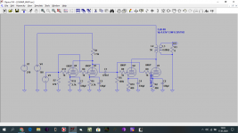
Simple SE amplifier
I am going to use two double triodes: 6P3N as driver and 6P6N as an output tube. Since placing tubes in parallel should in theory decrease signal to noise ration, I am thinking of using both double triodes for one channel.
Results are obtained from simulated Anode curves
Driver stage
HT will be around 200V, so I am going to use Ra = 10K for 6N3P, this should give Qsc point of Va = 132V, Ia = 7mA (for one triode), if I am going to connect two triodes in parallel I expect that current will double. Is that correct?
MU is around 35 so with two triodes connected in the stage I expect resistance loaded Voltage gain to be around A=20. (Not sure that is enough?)
Also added grid stopper resistor of 1K - cut off freq. above 20kHz - is this value work ok?
Output stage
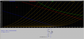
Maximum anode dissipation for 6n6P both triodes is 8W. Z(out) = 200^2/8 = 5K nearest standard output transformer value is 5.2K (there is a cheap option of 5VA, 5.2k, how do I calculate if VA rating is sufficient for an output transformer?). Do I need to use grid stopper in this stage also?
Qsc point of Va = 200V, Ia = 35.5mA (I am guessing for both triodes?) Mu is 15, so I expect with two triodes connected Voltage gain to be around A=13.
At this point I am trying to simulate stages and full amp with LTSpice
any suggestions, corrections, opinions, advice is very welcome and will be appreciated
Simple SE amplifier
I am going to use two double triodes: 6P3N as driver and 6P6N as an output tube. Since placing tubes in parallel should in theory decrease signal to noise ration, I am thinking of using both double triodes for one channel.
Results are obtained from simulated Anode curves
Driver stage
HT will be around 200V, so I am going to use Ra = 10K for 6N3P, this should give Qsc point of Va = 132V, Ia = 7mA (for one triode), if I am going to connect two triodes in parallel I expect that current will double. Is that correct?
MU is around 35 so with two triodes connected in the stage I expect resistance loaded Voltage gain to be around A=20. (Not sure that is enough?)
Also added grid stopper resistor of 1K - cut off freq. above 20kHz - is this value work ok?
Output stage
Maximum anode dissipation for 6n6P both triodes is 8W. Z(out) = 200^2/8 = 5K nearest standard output transformer value is 5.2K (there is a cheap option of 5VA, 5.2k, how do I calculate if VA rating is sufficient for an output transformer?). Do I need to use grid stopper in this stage also?
Qsc point of Va = 200V, Ia = 35.5mA (I am guessing for both triodes?) Mu is 15, so I expect with two triodes connected Voltage gain to be around A=13.
At this point I am trying to simulate stages and full amp with LTSpice
any suggestions, corrections, opinions, advice is very welcome and will be appreciated
Attachments

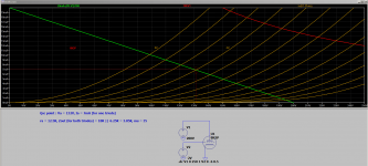
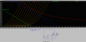
I am ploting loadline at 200V and 5.2k resistance and after that I am moving this line (with the same slope) up until I get to my desired workink point.
Is it a valid approach? But yes I modeled with only one tube so probbaly two tubes in parralel would be better.
Is it a valid approach? But yes I modeled with only one tube so probbaly two tubes in parralel would be better.
Last edited:
Hello.
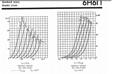
For you, the appearance of a single tube characteristic looks the same as a parallel tube. The slope of the characteristics after double connection of tubes increases twice. For you, for a single tube and for parallel tubes the point is almost the same 200V 36ma -6V. When you look at the original characteristics of a single tube, you can see 200V 35ma -6V. I have 200V 44ma -8V for parallel tubes.
Piotr
Attachments
Hi rplate,
Something is chancy in your design : the two stages share the same power supply. In SE that’s the best way to create the famous “motor boating”.
Solution : filer your B+ with RC filter : you will reduce the first stage power supply ripple, and voltage will become independent from B+ fluctuations. Try 1k8 with 47uF ( less than 10 mS time constant).
Regards,
Jérôme
Hello.
The slope of the characteristics after double connection of tubes increases twice.
Does that mean, that after connecting two tubes in parallel quiescent current will double? That can't be right.
Hello.
When you look at the original characteristics of a single tube, you can see 200V 35ma -6V. I have 200V 44ma -8V for parallel tubes.
Piotr
Could you show me how do you calculate current for parallel tubes
Last edited:
Hello.I have 200V 44ma -8V for parallel tubes.
But it looks like this Qsc point is exceeding maximum anode disipation value?
Hello.
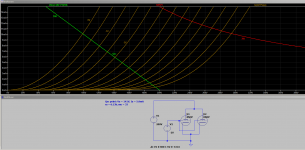
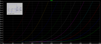
Yes, the power is exceeded but this is just an example that the characteristics of a single tube are different from parallel tubes.
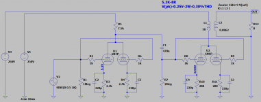
The construction of such an amplifier does not make sense large THD low power, it is better to use other tubes. I made your amplifier design and see for yourself.
Piotr
Yes, the power is exceeded but this is just an example that the characteristics of a single tube are different from parallel tubes.
The construction of such an amplifier does not make sense large THD low power, it is better to use other tubes. I made your amplifier design and see for yourself.
Piotr
Attachments
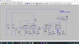
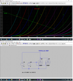
Schematic in Post # 1 has multiple errors.
Schematic connections in Post # 10 are correct.
A. Individual grid stopper resistors
B. Individual self bias resistors and bypass caps (4 and 4) for better balance of the cathode currents. And those individual resistors allows you to measure the currents, and see if a triode is bad (poor current balance).
C. Separate B+ for input stage, and output stage.
I did not check the resistor values for the self bias resistors, plate load resistor, and capacitance values for the coupling cap, and for the self bias bypass caps; nor did I check the operating points of the triodes, and plate dissipation.
But that circuit plan should essentially work, given the right resistor values.
Last edited:
You won't be getting 2W out of 6N6P, especially with 5k OPT
BTW, plate impedance of paralleled 6N6P is around 900 Ohm, so ~2.5K OPT would be much more appropriate if you need decent power at the output (and still that'll give something like 1.2-1.5W)
BTW, plate impedance of paralleled 6N6P is around 900 Ohm, so ~2.5K OPT would be much more appropriate if you need decent power at the output (and still that'll give something like 1.2-1.5W)
Hello,
Pa>6N6P=(250V-8.95V)*(8.95V/280Ohm)=241.35V*0.032A=7.72W (max Pa=4.8W)
Pa>Parallel_6N6P=2*Pa_6N6P=2*7.72W=15.44W (max Pa=8W)
Piotr
Pa>6N6P=(250V-8.95V)*(8.95V/280Ohm)=241.35V*0.032A=7.72W (max Pa=4.8W)
Pa>Parallel_6N6P=2*Pa_6N6P=2*7.72W=15.44W (max Pa=8W)
Piotr
Last edited:
Pa>6N6P=(250V-8.95V)*(8.95V/280Ohm)=241.35V*0.032A=7.72W (max Pa=4.8W)
Pa>Parallel_6N6P=2*Pa_6N6P=2*7.72W=15.45W (max Pa=8W)
Yeah, need to do some more thinking, thanks!
You won't be getting 2W out of 6N6P, especially with 5k OPT
BTW, plate impedance of paralleled 6N6P is around 900 Ohm, so ~2.5K OPT would be much more appropriate if you need decent power at the output (and still that'll give something like 1.2-1.5W)
I could try to use 1,73k OPT, 1.5W will be plenty, when I deal with exceeded power ratings (which I probably could get away with lower HT). Cool thanks!
Hello.
And what do you think about Parallel_ECL86 in triode + Parallel_ECC88?
Piotr
You are against 6N6P aren't you? 😀 Thing is I have these tubes on hand and if I somehow destroy them, I would not mind.
Parallel_ECL86 in triode + Parallel_ECC88 looks very good indeed.
I guess this is the best I could get with 6N6P in this topology. What is the actual power I could expext from it with 5,2k OPT? less that 1W?
Attachments
Last edited:
Hello.
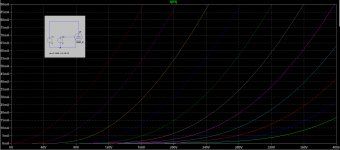
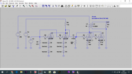
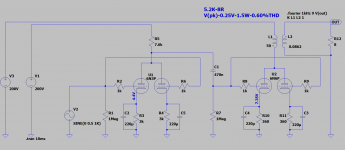
I'm not an opponent of tube 6N6P I have several projects where is the input tube or driver. Only as an output tube it gives little power but if 1.5W is enough for you I modified your design and now the loss power on tubes Parallel_6N6P = 8.2W and the output power is 1.5W at 0.32% THD.
I'm not an opponent of tube 6N6P I have several projects where is the input tube or driver. Only as an output tube it gives little power but if 1.5W is enough for you I modified your design and now the loss power on tubes Parallel_6N6P = 8.2W and the output power is 1.5W at 0.32% THD.
Attachments
Something like 0.4-0.5WWhat is the actual power I could expext from it with 5,2k OPT? less that 1W?
Only as an output tube it gives little power but if 1.5W is enough for you
at this point since this is my first build I don't know how much 1.5W actualy is, I have nothing to compare with.
I modified your design and now the loss power on tubes Parallel_6N6P = 8.2W and the output power is 1.5W at 0.32%THD.
Looks good! With these different supplys do you have to have different winding from power transformer of you can implement potential devider and filter it?
- Home
- Amplifiers
- Tubes / Valves
- SE amplifier design process