Aditional super tweeter to Tannoy DMT15 mk2

Dear all,

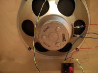
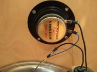
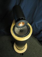
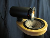
There are some ideas about adding super tweeter on top of cabinet. Yes, Tannoy has some ST models ST-25, ST-50, ST-100 and ST-200, but they are incredible expensive and there is a lack of custom hand made solution, so I will try to do it myself. Cheaper and on my own.

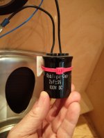
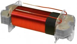
Is there any suggestion for driver, xover network (suppose that network will be only one capacitor or two capacitors and one inductor)....

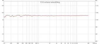
Somewhere I found that for my driver is xover frequency is 16 kHz.

So, at this moment - I have nothing and any suggestion is more than welcome.

If you can, please navigate me.

Thank you all, regards,

Boris

FS: Open Baffle Full range & EL84 SE amplifier

I`m posting the Ads here, there may be interested buyer in the Montreal Area... And since I know that this is the kind of stuff we DIYer like, here it is... A very good price to play with SE amp and open baffle...

See on Canuck: FS: Full Range Open Baffle speakers and tube amplifier system For Sale - Canuck Audio Mart

For Sale complete system (DIY) includes SE Tube amplifier EL-84, with tube rectification and two matching Full range Open-Baffle speakers, all DIY made. System is working fine, part of an Estate sale, and sold as is. Since it is very large and heavy, local sale and pickup in Montreal/Laval Area only.

Amplifier: Very nice built with audiophile parts (Kiwame, Mills resistors, Cerafine & Solen caps, CLC filtering, point-to-point assy. Includes an ALPS volume control. RCA inputs and speaker binding posts. Tube complement: Tube rectifier EH 6CA4-EH, gold pin, 1x ECC81 Telefunken, 2x EH EL84

Speakers: Open baffle design, Full range 12'' 'Zenith' 49CZ903 (Actually selling for 279U$ on ebay...), Super Tweeter: Big-Air Acoustics S-CFM, Super tweeter cap Obbligato Oil, 1.25'' wood front pbaffle, very nice condition.

Driver on ebay: Matched Pair Vintage Zenith 12" Speakers Woofers P/n 49CZ903 1960 Very for sale online | eBay

Would like to sell the kit, and since the price is way under the cost of parts, price is firm at the moment.
That's an excellent price for anyone that woudl like to try or experiment with a nice SE amp and Full range drivers...

Accept Cash on delivery, EMT bank transfer or Paypal (add 3% fee or 'Friend and Family)

Attachments

  • IMG_20200601_122247.jpg
    IMG_20200601_122247.jpg
    367.5 KB · Views: 266
  • IMG_20200601_122134.jpg
    IMG_20200601_122134.jpg
    438.7 KB · Views: 264
  • IMG_20200601_122141.jpg
    IMG_20200601_122141.jpg
    414.1 KB · Views: 266
  • IMG_20200601_121452.jpg
    IMG_20200601_121452.jpg
    502.8 KB · Views: 263
  • IMG_20200601_122333.jpg
    IMG_20200601_122333.jpg
    377.6 KB · Views: 257
  • IMG_20200601_122328.jpg
    IMG_20200601_122328.jpg
    394.6 KB · Views: 105
  • IMG_20200601_122339.jpg
    IMG_20200601_122339.jpg
    678.4 KB · Views: 104

TA2003P radio

Hi everybody!

I tried to make a radio with TA2003P. It works very nice on FM, nothing to say wrong about it. The sound is clear. The only problem could be the ceramic filter (BPF88-108) for the antena, it takes too much of the active signal, but if is replaced by a capacitor of around 15pF or by an LC circuit in "T" the problem is easyly solved.

The big problem is for both TA2003P and its equivalent CD2003GP is that while AM working a good part of the band is occupied by a local or regional powerfull radio transmitter. While is centered, the audition seems to be crowdy and overmodulated, depending on the power of the radio transmitter for that area. I changed the coil oscilator or the capacitor either in series with the variable capacitor or in parallel with it but nothing changed. The only thing I can observe is that while adjusting the red coil for medium waves is that a half of the band is more sensitive or the other one. Does anybody know if there is a small artificial to solve the selectivity on the AM? On a commercial radio I saw two ceramic filters put in series through an 1nF capacitor, but even this solution doesn't work. I also tried to use the IC as an IF stage for AM and taking the signal after the mixer stage fron another radio, but, again the sound is somehow overmodulated and the sensitivity is not so good.

Any SM Pro Audio V-Machine owner here?

Hi all,

I purchased this stand-alone VSTi player some time ago. It worked great, apart from the fan noise, for which I already found a solution.

However, during the modification, I accidentally cut some PCB track. Now I need some help from another owner who could take a close-up photo of the damaged part. I would like to restore the track.

Any help warmly welcome. I understand a lot of units have been sold in Australia. (I suppose there isn't any chance to obtain the schematics, and SM Pro is out of business)

No Really Dear, It Followed Me Home.

I should have started this thread a long time ago, I just stuck my finds in with whatever amp I was working on at the time. I saw this one online for $25, my kind of price. But I have collected enough early era radios, do I need one more? I already let three SS organs with decent speakers go, and they were free. But I just got home, it was listed for an hour.

Butt ugly, but for what I want it for not an issue. I saw a cap can and a tube sticking out, an array of knobs, bass treble, selector, tuning, I was guessing. Messaged and said I'll meet him. Bought it without even looking at it, when he helped me to put it in my car, it wouldn't fit. I have bought a few and somehow squeeze it in, this one no chance. We left it by the house and I got my trailer.

Got it home, started taking the chassis out. It was at the bottom, a 12" speaker in the rear, might have a full range firing forward, the front panel is angled to face splayed outward. Got the chassis unbolted, wires going up to where the speaker is. Oh, did I mention it is -23 C (-10 F for all you disadvantaged on the wrong side of the border) and my fingers were starting to feel it unscrewing stuff. Got the back panel off and... ...a chassis with the power supply and power amp on it.

The bottom chassis was disconnected from the amp chassis and tucked in the top section. And behind the amp chassis facing forward, two more 12's. Well it is truly bizarre. Thought it might have been a home built but the tube layout label beside the amp chassis shows two sections. A VHE-809 RCA, schematic wonderfully available. I see from the service manual how the receiver was suppose to sit, looked like it was jury rigged on the side.

http://pacifictv.ca/schematics/rcavhe809data.pdf

The amp circuit a Cathodyne with a 12AU7 rather than a 12AX7, just one tube short of a Fender 5E3 Deluxe. Or a BF Princeton. I have never picked up an amp that is so ready to convert into a guitar amp. I am going to have to think about what I will do with it. Almost forgot. What good is a thread without a picture?


Vb5qIRs.jpg


And for good measure, the numbers on the speakers which I can find nothing about. 961380-2W 279437 RL111D-1. Silly me, in the service manual, Olson Curvilinear Speaker, the best in hifi by RCA.

PE 300-794 plate sub amp not working

Hello All.


I'm a noob here but a music lover for long time. Recently we moved and one of my subs isn't producing sound now. It's an old Parts Express 300-794 plate amp. The other unit is working fine. I swapped inputs, checked the voice coil etc. The unit seems to power up as it shows a green light.


I pulled both boards off the back of the plate but found no "smoking gun". No burns, no leaky caps.


Any ideas?


Thanks!

Attachments

  • PE300794.jpg
    PE300794.jpg
    124.4 KB · Views: 84
  • 20200601_100052.jpg
    20200601_100052.jpg
    1 MB · Views: 97

Back Loaded Horn Omni Speaker

I have a design for a compact full range speaker cabinet that is based on a cone. The up firing driver reflects sound 360* horizontally off of a supended object, and the back pressure of the driver increases low frequency gain through a folded tractrix horn firing down onto the floor, radiating horizontally. Although sounding complex it is quite simple in concept: as the cone is circular in plan, as are the baffles for the folded tubes of the horn, circles within circles.

Reading of transmission line and quarter wave length tunnels, it seems that for benefits gained, problems of frequency diminishing and booming are rampant causing much effort to stuff the tunnels to assist control of unwanted frequency interference, and thereby diminishing the benefits in turn. As well the architecture of these cabinets can cause much domestic disharmony, the dreaded WAF problem.

Essays by Klipsch and Dinsdale demonstrate the science of horns, where the pressure chamber of the driver (also called coupling and air chamber) has a throat at the beginning end of the horn, and as the sound travels through the length of the horn it increase in volume. This is the goal of the rear loaded horn. As well there is an equilibrium equation linking Volume of the chamber, Area of the throat, and the Cut Off Frequency. The volume and the area can increase or decrease the frequency above which it does not enter the horn for magnification.

I am asking the forum if they have had any experience with rear loaded horns and thr equilibrium equation that would set the cut off frequency. Additionally, the literature on the folding of a horn is not well explained but suggest problems at the bending points, understandably, and I would appreciate advise on what remedies can be applied to make the transitions more fluid and enhancing to,the horn.

With Thanks In Advance,

Dwightay,
Toronto - Anguilla

Pearl 2 - Destroying Pre-amp inputs

A few weeks ago I had to substitute my Pass B1 and Aleph 4 with my trusted Arcam AVR280.

Unfortunately my Pearl 2 instantly destroyed the input ICs on the Arcam.

After a bit of investigation I found that the Pearl 2 outputs briefly swing to almost +24VDC on power on.

The B1 can cope with that.

The Aleph 4 has zeners on its input to protect it.

I'm just replacing my B1 with a P1.7 together with a RCA to XLR convertor, simply to be able to use balanced connectors.

I can't find anything on the THAT340P datasheet to tell me if the new pre-amp can survive the 24V pulse from the Pearl 2 ?

I've got a reverse zener input box that I can use but I'd rather not use it if I don't need it.

There is an error on the schematic for the pre-amp, it is powered with +/-20V not 30V as shown.

Attachments

  • Schematic.jpg
    Schematic.jpg
    180 KB · Views: 483

Potential narrow dispersion/compression driver DIY options?

Upgrading and understanding multichannel and its related acoustic treatment plan has been long and arduous. But I am confident I am versed well enough to move forward and make a sound decision within my budget.

Because my small apartment is fully treated with acoustic panels(reverberation under .2sec) I thought going multichannel might liven up most of the live albums I listen to.

I will upmix using a preamp processor and most of my music will be stereo but as it is live music I want to recreate the original event. And I have chosen multichannel to help with that.

The thing is my speakers are wide dispersion speakers(have no exact info on them) they are the Troel 3WC. I am aware that a 5.1 system should be medium to narrow dispersion speaker.

I also would love to have a narrow dispersion speakers in general that has a large 12 inch or 15 inch with a compression driver as I love fast attack, immediate, dynamic and transient speakers, The problem is that I already have the Troel 3WC.

If go for a centre 3WC and a matching ScanSpeak rear speakers I am looking at around $1000.

I am considering choosing a controlled directivity speaker with compression mid from about 600hz. This way I can have great stereo system for my studio and techno recordings and use a 5.1 arrangement with the same speakers for my multichannel system.

What options do I have with controlled directivity speakers which would be on par with Troel's design have a compresssion driver with descent crossover taking into consideration most design parameters? What I mean is that most PA type speakers have simple crossovers and are really just plain PA, I would like descent PA speakers for home use, really no point upgrading if the new speakers are nothing special. I am happy to go with speakers for the rear for now if I can find something for about 1k for 3 speakers for the front that match these needs. Can anyone recommend me some proven designs?

Please remember I will DIY everything I need a proven design that has descent drivers. This should bring down the cost and with American drivers I might have a chance.

My second question is does anyone know how wide dispersion speakers will fair in a multichannel set up and perhaps how it will go against a PA version(mentioned above) in a 5.1 system...?

Reckhorn DSP-6 users opinions

Hi Guys

I came across this great looking device. Has anyone used it yet, what do you think?

DSP- 6 digital speaker crossover pre amp + power amp | Reckhorn

I would like a device that took the high resolution digital output from a CD\DVD\BluRay and performed all processing in the digital domain converting the outputs to analog once. Could this be it?

What else might be better?

Thanks!!

Scott

FS: Scanspeak 18W/4531G00 (New, Pair)

For Sale, pair of brand new, never used Scanspeak 18W/4531G00, 4 ohms

Part of an Estate sale. Drivers are brand new, never used, still in their original box.

They sale for 287$CAN ea form Solen in Canada, or 209U$ from Madisond in the US

Asking 300U$ for the pair, a great price! + shipping + 3%Paypal

Thanks for looking
SB

Attachments

  • IMG_20200526_105006.jpg
    IMG_20200526_105006.jpg
    394.4 KB · Views: 268
  • IMG_20200526_105014.jpg
    IMG_20200526_105014.jpg
    381.2 KB · Views: 268
  • IMG_20200526_105036.jpg
    IMG_20200526_105036.jpg
    365.6 KB · Views: 265

Brook 12A Mono blocks

A very long gestation period for these as I started accumulating tubes almost 10 years ago-good thing as they're much more dear now. As for the particulars, outputs are 6A5G's, subbing for the 2A3's in the original. The input is 6F8G, an obscure and great-sounding 6SN7. Power transformer is custom wound by Heyboer, OPT's are Electra Print. I had to add a choke in the power supply as hum was unbearable without it in spite of increased capacitance. They sound wonderful, like listening to all my music for the first time. Many thanks to some of you who answered my queries concerning this build and especially to Briney who has built the same, although more true to the original.
http://www.diyaudio.com/forums/attachment.php?attachmentid=547561&stc=1&d=1462561142
http://www.diyaudio.com/forums/attachment.php?attachmentid=547562&stc=1&d=1462561142

Attachments

  • IMG_0882.jpg
    IMG_0882.jpg
    974.7 KB · Views: 1,094
  • IMG_5763.jpg
    IMG_5763.jpg
    997.3 KB · Views: 997

POWER FOR SSD

Pchifi, power supply is a key point, the thousands of dollars of data line of SATA is played, but it is still the main power supply for hard disk power.

No matter mechanical or SSD, the 2.5-inch hard disk only uses a set of 5V power supply. In this scheme, 12V voltage from the power supply line is used for secondary processing, and power is supplied to the hard disk after noise reduction and voltage stabilization.

In the output stage, tps7a8300 with noise as low as 6uv is used, which enables the hard disk to escape from the complex ripple environment on the host

Inductor value

Hi everybody.

I have an iron core inductor that currently has a value of 1.8 mh.

I need to change it to 3 mh. The supplier has none in stock and the part would be back ordered til who knows when.

Would it be possible to change the value of this by adding windings or would I be better off to buy another?

I have a DATS v3, so I can test and fine tune.

If this is something anybody has done please tell me what and how.

Thanks!

Attachments

  • superq.jpg
    superq.jpg
    187.7 KB · Views: 166

Cathodyne tube line pre

Hello,
want to build a Cathodyne tube line pre.
Could this schemo be a good starting point for the design?
Is a single ended 15K:600 Ohm output trannie of any use for this circuit?

Or will the output resistance of the circuit be too high and a different tranie must be used?

Many thanks for checking the schemo.

Attachments

  • 159567_2_En_10_Fig11_HTML.gif
    159567_2_En_10_Fig11_HTML.gif
    52.9 KB · Views: 354

LX mini quest

Would like to share my recent toys with all of you.

Speakers are based entirely on Mr. S.Linkwitz LXmini speakers design and all royalty's belong to him.

Reading on a web a god bunch energetically charged reviews and even leaving Don Keele`s masterpiece in a dust .

I decided to build a pair of LX mini`s and take a look closer to that original Mr. Linkwitz design.
The first build of LXmini`s was with in mine opinion improved drivers - woofer is Dayton Audio 6" reference paper woofer RS150P4 and full range is Markaudio Alpair 5.

Don't get me wrong it is a huge amount of beautiful things about that design and most of them way above average, but…..6 inch woofer just can't do it ...it is just not enough space in those drivers for musical instruments. Real woofers with such driver configuration is just a must.

Second version was more grown up ...woofer - Philips AD8066-W4-8 inch and speakers pipe volume has changed from 8 liters to 25 liters, full range driver is Markaudio Alpair 7A Gen. 3A.

And what a difference it was !!! Sound became relaxed and natural, sound stage huge, live recordings became a live, no one was “raping” violins and cellos any more .

It is enough bass to shake glass in windows frame.

It is possible to live with such speaker configuration happily ever after but….. It is a lots to ask from one driver to behave nicely and in civilised manner from 30 Hz to 700 Hz alone.

Attachments

  • IMG_0138.JPG
    IMG_0138.JPG
    876.8 KB · Views: 1,762
  • IMG_0147.JPG
    IMG_0147.JPG
    850.8 KB · Views: 1,742
  • Rew.jpg
    Rew.jpg
    41.4 KB · Views: 1,693
  • IMG_0153.jpg
    IMG_0153.jpg
    203.9 KB · Views: 1,751
  • IMG_0156.JPG
    IMG_0156.JPG
    905.3 KB · Views: 1,632
  • Rew1.jpg
    Rew1.jpg
    41.8 KB · Views: 669

Why did my TOA3255 blow up!?

Why did my TPA3255 blow up!?

Just wanted to get some pointers on my TPA3255 build. This is what happened:

1. Assembled the PCB, measured all key resistances, all within expected ranges, not shorts anywhere.

2. Power up on the bench PSU 21V for PVDD and 12V for GVDD. There was a very brief 1A draw on the 21V, I initially thought this was the capacitors charging but it might not have been.

3. I measure the DVDD and AVDD outputs - all good 3.30V and 7.77V.

4. Then I measure the output voltages expecting around 10V but nothing. Well, nearly nothing. All the outputs measured around 300mV to GND. I now notice the 21V current draw is below 10mA.

5. I now turn the PSU off and leave the circuit for a while reading the datasheet.

6. About an hour later (enough time for the caps to fully discharge) I turn the PSU back on then I get some magic smoke and full CC mode on both the 21V and 12V. 2.5A for 21V and 0.5A for 12V.

I'm baffled. My circuit looks good and everything went together well. Does anyone have any ideas or can spot any mistakes in my schematic before I go burning through more ICs?

Thanks
Boscoe

PS. If the circuit turns out to be fine, I can donate some PCBs to whoever can help!

Attachments

Marshall Modefour MF350

Hi


I am working on these amp which had its fuse keep blowing. I noted that one of the 4 power ICs has cracked open. I have checked all the resistors, elect caps, diodes and transistors on the main board and they are OK. I noticed some bad joints, so I resoldered the whole board. Now I have put in 4 new power IC modules, and replaced the two 47uf caps on each power board. I have not powered the amp yet. I plan to use a variac, without plugging in any signal and any load, I intend to connect a DMM at the speaker output and bring up the variac slowly while monitoring for any DC offset. If no DC offset, then turn off the amp, plug in a signal and speaker and then turn the amp back on while bringging up the variac slowly. What I want to know is, Is it safe to turn ON the amp without plugging in any load. Will it damage the power ICs. Please advice.


Thanks

Attachments

Universal HV boards

Ive designed and ordered these universal HV rectification boards. They are designed to suit the majority of power supply applications below 500VDC.


The boards measure 51x150mm and have M4 mounting holes 5mm from the corners and in the center of the board 5mm from the edge. Due to its size it should mount conveniently against the wooden chassis of most amplifiers.


The electrolytic footprint is for a 35mm snap-in capacitor. and will accept the majority of twin pole electrolytics.


See the attached schematic, the board is made to be used with either solid state rectification or tube rectification if D1 and D2 are jumpered and D3, D4 left out.

The first capacitor is either a 35mm diameter snap-in (c3 ) or one or two 37.5mm pitch Wima MKP4 4.7uF 630VDC caps for tube rectification.


Filter options are CRCRC or CLCRC, there are external connections for a choke.


The boards are tin plated and ROHS conform.

Aksing €8 per board ex postage.

Attachments

  • Universal HV board JLC.png
    Universal HV board JLC.png
    75.4 KB · Views: 110
  • UniversalHV Board.png
    UniversalHV Board.png
    49.6 KB · Views: 110
  • UniversalHV schematic.png
    UniversalHV schematic.png
    38.8 KB · Views: 110

Adcom 555ii rebuild

I started this thread not because there aren't others but because these are mine and I am going to approach them probably a little differently than others and I know I will probably get into a bind and need some help,

I picked up these two amps that are in excellent condition inside and out and it doesn't appear to have any cap problems yet so I decided to do it myself rather than go thru the pain of shipping them again.

So far I have replaced C806,7,8 & 9. I have a 50a at 600v bridge for a replacement and some 4.7K ohm AT 7watt bleeders that I am waiting for. I need 4 .o1uf at 400v or so X2 long lead that are hard to find if anyone knows of a source let me know.

Attachments

  • 20160213_165757.jpg
    20160213_165757.jpg
    59 KB · Views: 389
  • 20160213_165802.jpg
    20160213_165802.jpg
    59.6 KB · Views: 383

Looking to restore pair of AR3s

Hi all. Looking for recommendations on who can restore a pair of AR3 speakers. I live in Tucson AZ and I'm not really a DIYer, but thought I could get some useful advice. Tweeters, mid-range and woofers all work, and in spite of their age the foam on the woofers have no visible cracks and still seem pliable (one woofer was replaced about 25 years ago). Some pitches seem to jump out almost as if they were triggering a sympathetic vibration somewhere, especially in the octave just below middle c. I'm sure the speakers are far out of spec after all these years because the sound is muddy and in general not what it used to be.

RVILS

Bluetooth + amixer volume control

Hi,

I'm using the following .asoundrc file:
Code:
pcm.!default {
  type plug
  slave.pcm plugequal;
}
ctl.!default {
  type hw card 0
}
ctl.equal {
  type equal;
}
pcm.plugequal {
  type equal;
  slave.pcm bt
}
pcm.equal {
  type plug;
  slave.pcm plugequal;
}
pcm.bt {
    type plug
    slave.pcm {
        type bluealsa
        device "32:00:00:02:84:BD"
        profile "a2dp"
        delay -20000
    }
}
I cannot change the volume in the Bluetooth device using amixer. I tried:
amixer sset PCM 0% -M
amixer -D default sset PCM 0% -M
amixer -D bt sset PCM 0% -M
The volume doesn't change.

Thanks!

Hello from Blackburn area UK

I blame the present lock down for getting me back into tube/valve technology. Having stopped work and being stuck in the house meant I needed to do something that used my time and I hate gardening.

I picked up an old PYE valve radio prior to the restrictions so had some fun cleaning and repairing the case for that. Next I ordered some old military cold war gear from Ebay and was lucky enough to get that before the seller shut shop for a time. It contained sub miniature 6021 and 5840 wired valves, so had a look on the web for circuits, came across a couple of small guitar amps using the 6021. So also learning to use Kicad I did a board design with some negative feedback and had 5 boards made and built me some small amps.

The first one used a Hammond 125B output transformer, The next one used a small home made PP output transformer from recycled laminations but lacking frequencies under 200Hz, so with slightly larger transformer wound a couple more to make a simple milliwatt stereo amp.
At this stage the bug seems to be with me, I have some EL84's from Ukraine on the way, but also fancy making an amp with some TT15 valves. I am lucky in that I can make a basic aluminium/steel chassis in the garage if required having a few machine tools.

It is strange that I have not listened to as much music as I have recently on my small amp, typical as my hearing is getting worse with age.

Adrian

Attachments

  • amp8.jpg
    amp8.jpg
    94.6 KB · Views: 107
  • amp9.jpg
    amp9.jpg
    45.5 KB · Views: 103

diy repair newb from florida, need help with a boston hps 10se

Hey, my name is Zach. I have a Boston hps 10se subwoofer with built-in amp that has stopped working. It is able to turn on, however no power goes to the speaker. I tested the speaker with a different amp and the speaker works. I did a good ol' smell test and noticed a slight odder around the caps caps in the first pic. The cap being pointed to in the pic is getting very hot as well. I also noticed that when I put the switch into auto mode the amp doesn't go into standby even when nothing is connected to the inputs.

update: After letting the system sit powered for a bit, both of the caps in the first picture are getting hot.
As soon as I finish unpacking and finding my tools I am going to further disassemble the amp and take some more pictures for you guys.
Although, if anyone has any ideas for what could be wrong and or if its just those caps that are bad, please let me know before I have to start ripping off that nasty glue that most of the boards are smothered in.
Also some background info on the unit, my neighbor was bringing it outside to throw out and I took it off their hands, it recently stopped working and they just decided to get a new one rather than have it repaired.

Attachments

  • IMG_1271.jpg
    IMG_1271.jpg
    755.8 KB · Views: 1,185
  • IMG_1272.jpg
    IMG_1272.jpg
    861.5 KB · Views: 445
  • IMG_1277.jpg
    IMG_1277.jpg
    593.6 KB · Views: 456
  • IMG_1278.jpg
    IMG_1278.jpg
    547.6 KB · Views: 409
  • IMG_1280.jpg
    IMG_1280.jpg
    609.1 KB · Views: 451

Boston Subwoofer HPS 10se humming

Hi I am new here and am in need of some help. My subwoofer jsut recently started making a humming noise(60hz) and disconnect it from the home theater and it continues to him with power. The unit when connected receives bass and plays but with the humming. I’ve taken it apart and checked the capacitors and they seem good but haven’t tested them. Also I have moved it to another room to see if it was ground interference but still has a the hum. It becomes louder when polarity is flipped 180. Any help on diagnosis would be much appreciated.

DIY amp completed - part I : PGDlx and PGJ.

OK Guys - I may have posted some pictures about them many years ago, but since I reworked these amps recently and also because my previous picture hoster collapsed... I repost... 😱😉

(Just click on the pics to see them with correct proportions, and then real size with clicking the icon at the left bottom of the pic 🙂 )

The Paul GUILHEM Deluxe (lower) and Paul GUILHEM Junior (upper) :

z7I9Ib-P1050677.jpg


w7I9Ib-P1050678.jpg


The PGDlx offers some extra facilities from now on :

qX4FJb-PGDlx-Fav-Far-31-05-2020.jpg


- A FSWable booster (below the input jack).
- A Fixed/Cathode bias operation SW (HIGH/LOW).
- A rectifier mode SW (Valve/Diodes).
- A feedback SW (Tight/Loose).
- 14 to 24W RMS clean power output, depending on the power stage and PSU modes selected.

The PGJ offers less - due to its compact size :

tX4FJb-PGJ-Fav-Far-31-05-2020.jpg


- A FSWable booster (at the back).
- A Presence rotary switch.
- A Triode/Pentode mode SW (HI/LO).
- 5 or 23WRMS clean power, depending on the power stage mode selected.

But none of them are lightweight... 23.5Kg for the biggest, 14.5kg for the smallest... 😱

A new version - even more compact - of the PGJ :

AQJtJb-PGM-int-01-04-2020.jpg


Size comparison :

imGDJb-P1090564.jpg


TN2uJb-P1090592.jpg


And still heavy... 🙄

A+!

Dolby atmos speaker replacement/upgrade

Hi all, I am currently looking to replace just the speakers in my upfiring modules. I bought the Onkyo SKH-410 knowing they are not the best but mainly to check the effects work in my room, which surprisingly they do very, very well.

So although the effects are really good and sound appears to come from my ceiling, I can tell the sound quality is not that great. So what I am looking to do, is just replace the actual speaker, leaving in the cabinet the circuit board that deals with the special frequency response. I have taken the grill off and the speaker is just screwed in so nice and easy to change.

Having done some research, I am looking to replace them with some Faital audio pro speakers

I would like to keep the cabinets as they fit nicely where they are. Can anyone see any reason why this would not work?

My first build: need help on porting and enclosure design

Hi guys,
I am a total newbie when it comes to speakers. I just got into it after my grandpa passed away and I got their stereo receiver. The stereo receiver can take 4 speakers, 2 channels A + B, with the minimum of 12 ohms per speaker if channels A + B are going. If it is A OR B, 2 speakers, the speakers are a minimum of 6 ohms each. These speakers are running in parallel, so the stereo system can handle a minimum of 3 ohm total. Stereo receiver is a Yamaha RX-395, where the manual says 45W + 45W RMS output power. For some reason, I want to have 4 speakers (really only using for my TV, like video games, and music, nothing crazy), so I started doing more research and looking on Facebook market if I could find some 12 ohm speakers. No luck. I looked into wiring and discovered I could wire 2 6 ohm speakers in series to make a 12 ohm box. That is when I took on creating my own speaker boxes. I have decided to make 4 speaker boxes, with 2 6 ohm speakers in each box, wired in series.
I watched some YouTube videos and decided to go with a full-range driver. I got 8 Dynavox LY401F 4" Full-Range Driver which is 6 ohms and has a decent frequency response. I started researching on designing a box after the drivers arrived and from a calculation I made, it appears I would need a ported box for more base. From this site, Speaker Box Enclosure Designer / Calculator, it is saying I need 1" diameter and 4.76in in length. These calculations are based on 1 speaker in a box, I plan on doubling everything (so two ports for one box). Wanted to check if that is accurate or not in the first place? Secondly, based on what I have looked at, I would like this port, Speaker Cabinet Port Tube 1" ID x 4" L Flared, but it is only 4 inches long. There is this other one, Speaker Cabinet Port Tube 1-1/8" ID x 6-1/2" L Flared, but it has a larger diameter. Which one would you get? I want the shorter one in length, but I am not sure, which measurement is more important?
I may be overkilling it with 4 speakers, but I am having fun with it, and that is all that matters. Curious what tips, tricks, and suggestions you guys have. Thanks for reading and helping!

Hello everyone.Back again and anxious to start soldering!

Hello everyone. Back after a long time. Have been listening to music through asus
Essence stx on my computer. Very happy with quality but thinking about class a with discrete components. Lots of heat sinks lying around. I have several good headphones BD 990, HD800, AKG 271, etc. Looking for clinical yet creamy sound. I know creamy usually means tubes but would like to try solid state for now. Any schematic suggestions? Not a pro but pretty good with schematics and soldering, etc. Any advice greatly appreciated. Thank you.

v3 power supply testing

hi - i am about to test my F5. I am planning the following steps

1)test the softboard unconnected

2) connect softboard -> transformer (unconnected secondary)

3) transformer -> v3 PSU. not connected to the F5 board. The question is if it is unconnected, how would the PSU discharge itself?

4) test L and R channel separately.

Would this strategy work? i got a light bulb tester widget.

thanks alot

Philip

Bridged topology with common-mode control

Inspired by brilliant shine of Blowtorch four-quadrant self-biased input stage and trying to build something bridged we need to control output common mode.


This is the one more or less simple approach, based on the current summing of two nodes. First loop are controlled by input signal, while second are controlled by output common mode.

Attachments

  • Bridged with common mode control.png
    Bridged with common mode control.png
    42.6 KB · Views: 422

BuffaloPRO build thread

Let's see your BuffaloPRO builds here! Here is mine in preliminary form:
BuufPRO.prelim.JPG
BuffaloPRO (9038)/Mercury/Hermes-Amanero-Cronus (with a single 45.1584 XO)/DIY supply for digital/old Placid HD(temporary) for analog.
I plan to extend the aluminum angle stock acting as a heatsink here such that it can shield the AC input from the DAC section, and I will build some new supply for the analog section-I used the old Placid 'cause it was around for initial testing.

P-Audio BM15CX38 in MLTL cabinets

Dear fellow diy:ers,

Just wanted to post some photos of the MLTL cabinet I just finished for the P-Audio BM15CX38 coaxial drivers. The cabinet is designed by 'GM', who helpfully calculated the dimensions for me when I was inquiring at the yahoo MLTL group, if anyone had built such cabinets for those specific drivers. Many many thanks to GM!!
First impressions is that bass continues to improve after some
10 hours play time. The bass is now very powerful, and I can still hear improvements after each session. Big and dynamic soundstage from the coaxials. All in all, I am VERY impressed with GM's design and the MLTL type of enclosure. What I have to do now is build a proper crossover; I only use a 2.2uF capacitor for the tweeter right now.

Hans in Sweden.

New to this world, beginner help for wifi streaming

Hi I'm a casual-fi low-effort DIYer. I'm on the hunt for a nice solution to play spotify, airplay, and similar things through my existing amp & speakers.

I'd love for this to be as plug&play as possible but I know how to boot a linux kernel or solder a circuit board component if absolutely needed. One of the biggest things I'm after is an easy/seamless interface. I DO NOT want to have to go to a web browser in order to adjust the audio stream.

Most of our computers are Mac, our phones are a mix of Android and Apple.

I saw that there's an up2stream board available on amazon for $50 that almost fits the bill with airplay and an app for mobile devices, BUT it's 2.4ghz wifi only and we use 5ghz.

I'm only somewhat concerned about audio fidelity. Ease of use and total cost are much higher priorities to me.

Is a raspberryPi able to meet this need? Do I need to shell out for a Sonos Connect or similar non-DIY solution? Is there a competitor to up2stream that has 5ghz wifi modules? Did I miss a sticky thread that all beginners should read to understand the lay of the land?

I probably have lots of other questions, but any intro help that can be given would be lovely.

Is this SMPS schematic plausible?

Hi all,

I am trying to build a car audio line driver and need a bipolar power supply for the Op Amps.

I had a Boss AVA1210 Equaliser, which is terrible, but seems to have a tidy and compact dual rail power supply.

I have traced the circuit out and have come up with the schematic below, the idea being that if the circuit is plausible I will integrate it into the line driver PCB.

Does the circuit look ok, I will be reusing the original parts from the current PCB if possible.

I had wondered about increasing the size of the capacitors to bring down the ripple a bit but wondered whether the oscillation of the circuit depends on their values?

Attachments

  • SMPS v1.jpg
    SMPS v1.jpg
    712.5 KB · Views: 176

Bi amping proel tflv152p4

Hello guys

I bought a pair of used proel tflv152p4 but the driver were not working
i checked the wiring and seems that crossover was missing because the wires go from woofer/driver directly to speakon imput, but i since i'm a big noob i sent them to rapair.
Got them back on friday and at the shop they were working perfectly, so bought new amplifer and 4 poles speakon cables as suggested from the rapiar guy but still they were now working, so i check and wiring and nothing changed, still no crossover and direct wires
so at this point, if i just buy a new amplifer and external crossover for the drivers and the just weld the driver wires to output speakon will it work?
sorry if the post may be a big mess but i'm a big noob
also attached the pic of the actual wiring
fN5e6Gq.jpg

UcD desing notes wanted

Hello,
Lately, I have been reading about Class D amplifiers and have designed some of my own based around the Triangle Wave + Audio feed into a comparator. While reading more I found there was a lot more on the subject than it looked on the surface, reading this forum I discovered UcD which seems to be a nice technology and I would like to experiment with it. I am therefore asking for application note, whitepapers or anything which can give me a high level and also in-depth working of this topology.

I have searched for whitepaper and application notes on Mr. Google and found some from Hypex and Bruno, but there must be more to read.

I appreciate any good papers you know, or anyplace where I can find them.

Would like to stress that I'm not looking for your designs to make an amp, I want to learn how to make my own of course if you think they will help I appreciate but don't call me a design stealer

Thanks in advance 🙂

Using Car Amp at home (McIntosh Mcc404m)

[special=[special=50D11458-DFE4-427C-AC09-F17206A9A510.jpeg

5A8B3073-0399-42B7-87B5-2C8573CE7AA9.jpeg]%[/special]]%[/special]

Hello,

Hope everyone is well at those times

I’m stripping MCC404m from my car, I won’t be doing car audio anymore.
I thought of repurposing this amp as home amp.

1) Do you think it will be an upgrade over my current amp Adcom GFA-535?
On paper, MCC404 is more powerful 200w@8ohm bridged vs. 60w@8ohm.
But, MCC has lower S\N ratio 105db vs 110db.
MCC THD 0.007 bridged @ 4ohm. Any guess what it could be at 8ohm load? (Does it matter/audible in real life?)

Attached spec sheet for both amps. (MCC manual, Adcom from web)

2) I will need a power supply for MCC. From what I gathered I can use a PC PSU.
MCC is rated at 12v 70A (100W ??? This one I don’t understand - 12v*70A=840w...anyway, I believe I should get at least 1200w PSU - Corsair XH1200 or something along those lines).
Please correct me if I’m wrong, any input would be appreciated

3) my concerns:
- will PC PSU introduce noise into the system? In theory i can add a capacitor in the chain, the same one i used in a car.
- is PC PSU a safe option? Do they have build in protection? (Basically, will this setup be a hazard, even in case I’ll do everything else right - securely connected wires, insulated, all that)

4) other reasons not to do that?
I thought of doing it because I thought it might be an upgrade over Adcom,
MCC has some EQ capabilities which may come in handy (well, depends on how quality it is, EQ on my pre-amp that i used (also Adcom) definitely introduced some artifacts in higher frequencies, so idk),
Lastly, generally I think its just cool idea, and a fun project.

Thank you

Help to get started in audio electronics repair.

Dear knowledgable members,
I am at home during this crazy time with nothing but time and decided to expand my knowledge of trouble shooting and testing vintage amplifiers. This is something

I have repaired and spent a great deal of time building some amplifier kits, replacing caps in speakers, amps etc. This has all been done with much help from you guys in the past. Thank you.

My next step is to get a better understanding of electronics so I am not muddling my way through the process before I invest in test equipment, Oscilloscope, signal generator etc. I would like to be confident in my repair approach and I would love to be able to see how my amps are performing, watts rms for instance.

I am obviously a beginner and feel what I need is to have a greater understanding of the following.

1. How to read amplifier schematics

2. Oscilloscope grounding - floating ground - This really has me spooked even after watching many different videos on the subject, none of which has given me the confidence. I understand that most of my vintage gear is floating as they only have 2 pin plugs, but do I still need to hook my gear under test to an Isolation Transformer?

I am not necessarily looking for answers here, although that would be nice, but rather if anyone can direct me to decent resources that can help me.
One resource that I have found on Youtube is "xraytonyb". He does many videos on vintage repair/restoration and have found him to me very informative. The one thing which I find in all of these types of videos is the presenter does not show the exact locations of where they are hooking up test probes and leads.

Thanks you so much for any assistance any of you can give me.

Clive

Need Help with Luxman Tuner Repair

Hello All,

Once again I would appreciate some guidance from the many experts on the forum.

Back in 1989 I bought two Luxman T-117 tuners. One has been in daily use ever since. The second has been in a closet for at least 10 years. I recently thought I would set up the second one for use in my office. When powered up, no display showing signal strength or frequency selected. The unit appeared to be able to be tuned, but the sound was very distorted.

I opened the unit up, and visual inspection indicated two electrolytics with signs of leakage. One capacitor C001 (1000 µF/25VDC ) was the main power supply smoothing capacitor feeding a IC voltage regulator (L79N). I have the Service Manual for the T-117, which indicated this is a +12 V device. I measured the output and got 10.7VDC. I replaced C001 with the closest matching device I had on hand (1000µF / 50 VDC). This brought the main power supply back to 12 VDC, and now I had normal sound, and tuning control, but still no display.

The second problematic capacitor C007 (18mF / 5.5VDC) associated with a circuit block identified as “5V for memory back up.” I have replaced it with the closest thing I had available (3,300µF / 50VDC). Still no display.

The Service Manual is 24Mb, typical for the Japanese of that era, very detailed and complete, but too large to put on the forum. I have copied the schematic for the power supply and marked (with arrows) the two capacitors just discussed.

I measured the emitter voltage on Q1001 at 2.6VDC, the manual says it should be 4.17VDC, the schematic indicates this to be a +5V rail. So, I am unsure how to proceed, I could just start replacing the larger electrolytic caps, for example C008, even though I do not understand what the circuit block it is associated with is supposed to do. The connector CB001 connects to the circuit card containing the LCD display.

Any guidance would be greatly appreciated.

Cheers,

ceulrich

Which Midrange with Dayton RS225?

Hi Everyone, I just ordered 4x Dayton RS225-8 since they're on a good sale at parts express right now. I want to build a 3 way with them covering the low end, 2x in parallel for a ~4ohm load, 92.8 dB sensitivity 2.83V/1m. I might try building with the Dayton DSPB series DSP and amplification to make them active - always done passive before, so I thought it'd be a fun new thing to try.

I'm wondering what all of your thoughts are with respect to a couple midrange options I'm considering. I'm probably going to use the Fountek NeoCD3.5H as the tweeter.

The first option is 2x RS125-8 in parallel, running it as an MTMWW. I like this option because the voicing will match the woofers very well, their sensitivity is the same as the RS225-8, and it's only $30ish per driver. Downside is that it's 2 drivers, not 1, so I'd thinking imaging might not turn out quite as good (would TMMWW be better?)

The other option I find intriguing is 1x Satori MR16P-4. Pros here are that it's a single driver, so no vertical lobing to worry about, it's supposed to be an amazing mid range and it's 92.5 dB 2.83V/1m so it's a good match there for the 2x RS225-8. Downsides, it costs $100 more than a pair of RS125, and it's not an aluminum cone, which I imagine will result in worse timbre matching with the woofers and aluminum ribbon tweeter. I do usually like paper mids though.

Do these options sound like they'll pair well with the tweeter? Is either one significantly better than the other? Are there more options I should consider? I wouldn't want to go more expensive than the 2x Satori @ $300 total for midranges.

Thanks in advance for putting all your collective wisdom to work helping me out!

Adcom GTP-500ii popping while changing inputs

Hi, I just acquired a used and “working well” GTP 500ii tuner/preamp off from the bay. Truth is it’s not working well...

Problem is that it pops (considerably loud) when changing input sources, or when pressing the tone in button.

Volume knob has a scratchy-like behavior but more a breathing sound than a scratch.

Cleaned and lubed all front panel pots and buttons to no avail.

I’m inclined to thinking there’s an issue with a shunt capacitor somewhere. Sort of like having a DC current surge not going straight to ground but leaking into the signal path. But that’s just an idea.

Hopefully someone with experience in these units can chime in with informed ideas.

Thanks,
Luis

Control of BBB-based audio appliances

Thanks largely to the persistence of Miero and his work on Botic, the capabilities of BBB-based music players are steadily expanding. However, it is unreasonable to expect Miero to anticipate the preferences or needs of every builder. This thread is intended as a place to share our individual solutions to various control and integration scenarios - from the routine to very specialized. I hope you will consider showing off what you have done with your own hardware and software. I will do the same with my very basic efforts as progress is made. I'm keeping it as simple as possible using bash and python. Be forewarned, my approach here will be as a beginner whose knowledge is gained from trial-and-error with heavy emphasis on the error! 😀

To start, let me go 'pie in the sky' and present a couple of possibilities for controllers that I am thinking about but with which i have zero experience. The ideas and possibilities seem really transformative - really worth learning about. These control methods use mobile device apps (iOS and Android) that allow one to construct their own "remote controls" for lots of different kinds of devices. (Who doesn't have a retired smartphone that could be put into service?) Here, I'm thinking of controlling things like system inputs and outputs (e.g., a TPA OttoII), volume, other play parameters, etc. This can be done from a SSH command line, but these controller programs are truly multifunctional. I don't want to duplicate the many excellent controllers for MPD or Squeezelite, but how about controlling other equipment or room lighting from the same hand-held device? The internet of things is arriving. 🙄

NetIO is a fairly well-developed platform with an online design application for configuring controllers. A variety of widgets can be incorporated into the controls, like buttons, switches, sliders, displays, etc. Advanced controllers can be multi-page and programmed to change pages as the functions require. If I'm not mistaken, the control panel can also display information gathered from the 'slave' device. The interface between the mobile control device and the slave device is limited. Quoting the developer:
Code:
NetIO does not support SSH connections. It is only TCP sockets , UDP or HTTP and 
HTTPS.  
However, there is a project from simi-chan http://netioapp.com/de/projects/681 
that enables the execution of bash commands via NetIO without a special 
self-programmed server.
@kushal_mehta51 hostnames work, so if you have a dyndns address and the router 
configured correctly, you can just use the dyndns address to connect from the 
internet.

Blynk is the other DIY controller App. This is less expensive and is perhaps more broadly applicable, being employed in "lower-level" device control tasks as well as at the level of Linux development boards. If I'm not mistaken, there is javascript server code that runs on Rpi but that has not been ported to BBB. Both NetIO and Blynk host user forums, and it seems the level of discussion is more technical with Blynk. The Q/A is harder for me to understand. So I don't know which of the two systems would be easier to use after gaining working knowledge.

Are any readers experienced with either of these two systems? What is your advice?

Because my BBB is wired and not wifi, opening a TCP port doesn't worry me. So I will probably try NetIO using TCP enabled by Python scripts. I will report back when I know more. I will also share the interrupt and control scripts that are now about 50% done - along with photos, of course!

...looking forward to your thoughts and ideas... :idea:

Audio Note Conqueror problem

Hello,

I have a problem with AN Conqueror and I can not deal with it. It is quite old unit and I have change electrolyte caps to Audio Note Kaisai and standard. After this the resistor marked on the diagram has burned out. I have changed it and it burned out again. The voltage measured at this resistor with both 300b installed is 40V. With only one 35V. The 6sn7 heater voltage is 5,9V. The 300b filament voltage is 4,9V. What can be wrong with my amp and what else should I check?

P.S. In my unit there are two more resistors that are not on the diagram. First one is 10W 1R2 between 6sn7 heater and bridge rectifier. Second one is 2W 6k8 at the positive wire that connects B+ to board with 300b and 6sn7 tubes.

conqueror_100r.png

Broken headphones (Sennheiser HD202II)

Hello all! I've had these headphones (Sennheiser HD202II) for ten years and I love them. I've fixed (re soldered the wires) a bunch of times, but this time I think they're broken beyond repair. Unfortunately I don't have money to buy another ones so I'm hoping someone can help me figure this out.

The "plaque" (sorry, I don't know the term), that the wires are soldered to, came off. But what I can't figure out is that it is not connected in any way to the main speaker. It looks like there is a brownish transparent glue (which I can't imagine it being conductive). As far as I can see, it was glued to the black plastic (the "case" of the headphone).

Please, any comment or suggestion on what to do is much appreciated. There are pictures attached, but I can take more if needed.

Sennheiser HD202II - Album on Imgur

new to fullrange

hi- im new to full range but want to get a first hand experience in the subject-

i have small cabs- made from plywood- they have 10mm of bitumen and 50mm foam-
27cm x43cm x 19cm- my amp is dynaco sca-35

can you suggest a driver - i dont min putting a new front panel and port if required

price is not a huge issue as i can sell on if i dont like them

sp 001.jpg

Static from both speakers

I am having an issue where I am getting a static sound in both mid/bass drivers in my speaker build. This is the second time I am producing the same speakers and no static in the first pair.

It is a two way design with a second order crossover. The problem drivers are Eton Arcosia 6” drivers with the phase plug.

I have taken apart the speakers and resoldered them. I have checked the crossovers and no obvious issue there. I have tried 5 amplifiers in three locations. Happens in each location.

99% of the time the sound is fine. It is only on ultra deep bass notes that the static happens. The easiest way for me to trigger it is Three Wishes from Roger Waters. The Djini’s voice does it. Volume is loud, but not crazy. Maybe 80 to 85dB.

Any ideas?

Pioneer PL-560 Direct Drive Turntable: A Conundrum!

I have opened up on my bench a circa 1978 Pioneer PL-560 turntable. Here are the key details:

1. This has a direct drive motor. In at least one Pioneer service bulletin I found, there is a strong warning not to power on the motor without the platter installed.

2. This table does not have a dedicated "On" or "Power" switch. The only way that the various boards inside see any juice is when the "Start" button is pressed. This also starts the motor.

3. All of the boards and most of the adjustment pots are only accessible through the top of the plinth (see photo), which, of course, is blocked by the platter. . . . The bottom is not removable--it's what everything is mounted to.

My conundrum: How do I check voltages on the boards or carry out adjustments that require access to the pots (see attached example) if the table only sees power when Start is pressed, which can only happen with the platter on?

In theory, I need to isolate the switch for the motor itself and disable just that before pressing Start. (This assumes that the power for the rest of the table doesn't also feed through that same switch.) But if that were the case, you'd kinda think the Service Manual would mention something about that important detail.

Attachments

  • Wiring 1.jpg
    Wiring 1.jpg
    433.9 KB · Views: 966
  • Meter Adjustment.jpg
    Meter Adjustment.jpg
    62.1 KB · Views: 345
  • Schematic.jpg
    Schematic.jpg
    140.4 KB · Views: 368

ESD/EOS Filter for ADC Input?

Hello,

I'm designing a TLV320ADC6140 module that will be used as the ADC for 2 microphone inputs and a stereo "line level" pair.

The device has "anti-aliasing filters associated with the decimation stage, dedicated high-pass, and then programmable biquads..." and "the only required external components to evaluate the product is the AC coupling cap (which can be shorted out for DC coupled operation)." - TI

I plan on connected dynamic professional microphones such as an SM58 connected to an XLR jack, over a balanced XLR cable. On the other two inputs I plan on connecting a 3.5mm jack which will accept line level signal from devices such as phones, tablets, computers, etc.

I checked with TI and they said that i should consider adding "system level ESD or IEC type transient protection." and said that maybe "add a TVS diode in parallel with a ~100-470pF capacitor". So this is the circuit I have drawn.

attachment.php


We have the following parts:
  1. ES1 and ES2 are a TVS Diode with part number TPD1E10B06QDPYRQ1
  2. C11 and C25 are a CAP CER 100PF 50V C0G/NP0 0402 with part number C0402C101J5GAC7411

Is this a decent ESD/EOS Filter? We'll be using the microphones in the public with people passing them around and being rough with them in a karaoke environment. The line inputs will be phones, and tablets, plugged and unplugged frequently. Do you think this is a good circuit as an input for our ADC?

Thank you!
Jay

Attachments

  • ESD-EOS Filter for ADC Input.png
    ESD-EOS Filter for ADC Input.png
    10.8 KB · Views: 231

Optimus, Pioneer CD player TWINS?

I'm seeking an Optimus CD player with a Pioneer twin. The Opti CD-7250 has a Pioneer twin, likely PD-M403. Great, except they're 6 disc mag. players...not for me. The Opti CD-1660 (circa 1990-1992) looks like a good choice with 8x oversampling. If I could find a Pioneer 'twin' I would know where to look for spares when needed. Any ideas? Thank You, Randy.
Projects by fanatics, for fanatics
Get answers and advice for everyone wanting to learn the art of audio.
Join the Community
507,739
Members
7,886,256
Messages

Filter

Forum Statistics

Threads
406,144
Messages
7,886,256
Members
507,739
Latest member
c.gbarke2005