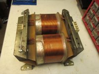
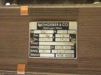
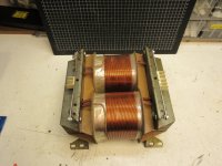
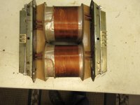
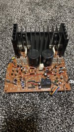
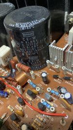
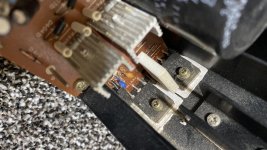
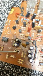
Toroidal transformer, where is the GND?

Hello guys,

I do soldering for years and I'm still missing some basics. GND is part of it. 😱

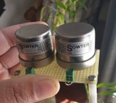
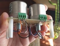
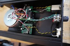
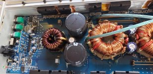
I have few strong toroidal transformers, but non has V-GND-V. I have two wires AC primary and two wires AC secondary. How I can make missing ground?

I know that some custom made toroidal has leaded wire from the middle of secondary wiring, I suppose it should be the ground...

Well I would like to make some GND on toroidal transformers, because I will need V+ GND V- for my amps. Any idea? 🙄

Thanks for help!

Milan

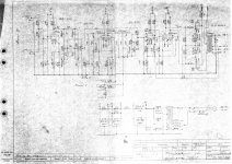
EL84 SE mixing mystery box

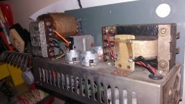
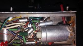
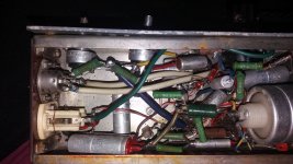
This is a mistery box I bought a few months back. Came with the output tube broken, whick turned out to be an EL84. It was impossible to even try to recap it as is, but I messed up while drawing back the grid/feedback line of the end tube.

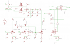
So far i have figured it to be a mixing amp with a single ended output.

These are the best pics to show the machine itself, but already into disassemly. 1970-80s balkan DIY technology at its finest.

Here is my drawing too, any input is appreciated about any part of it and thanks already!

Attachments

  • 20200302_162035.jpg
    20200302_162035.jpg
    846.9 KB · Views: 304
  • 20200302_162044.jpg
    20200302_162044.jpg
    833.1 KB · Views: 284
  • 20200302_162138.jpg
    20200302_162138.jpg
    874.1 KB · Views: 271
  • 20200302_162143.jpg
    20200302_162143.jpg
    893.6 KB · Views: 264
  • schema.png
    schema.png
    79.7 KB · Views: 335

FS: Paradise Phono PCB Set

Hi. For Sale a complete kit of PCB to build the Paradise Phono. Kit includes 2 paradise phone pcb (one per channel), the pre-reg power supply with CLC pre-filter and the CRC capacitor filter banks. This is my own pcb design based on the official Paradise design. I know it works because I built it! The Pre-reg pcb contains the dual transformers, dual discrete rectifiers and clc filter (one for both channel), then this raw +/- voltage goes to the CRC filter pcb, and then to each Paradise pcb. The Paradise pcb has built-in fancy discrete shunt regulator. Check my own phono preamp built.

Kit will comes with schematics and detailled BOM. Take note that you need to match a lot of transistors for the Paradise and this kit is not for beginners.

Total 85U$, set of 4 pcb with complete schematics and BOM...
Send me an email if interested...

Thanks for looking.
SB

Attachments

  • Paradise PCB kit.jpg
    Paradise PCB kit.jpg
    956.3 KB · Views: 1,807
  • Paradise.JPG
    Paradise.JPG
    159.4 KB · Views: 1,831

Output tube plate to driver cathode feedback

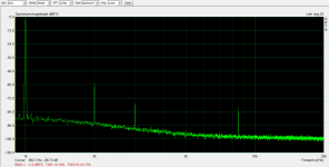
In another thread, I started investigating feedback from output tube plate to driver cathode in an SE amp. It seems to work extremely well. I'm getting 0.14% distortion at 1W, harmonics above 3rd are more than 100dB down, buried in the noise. Zout is 0.8 Ohm. I've only been able to find 1 SE amp online with better distortion at 1W (Pete Millett PL-177).

I'm happy with how this is going, but I'm not going to be satisfied until I fully investigate whether there are any easy ways to make it significantly better. My plan is to substitute a high-mu transmitting triode as the output tube for this amp in the final design, so I'm going to lose some gain and feedback when I do that.

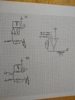
The overall approach is series-applied voltage feedback and I like to think of it like a big op-amp in series-feedback configuration with a large voltage offset at output (output tube plate) and a lower input impedance on the inverting input (see graphic). There are also undesirable AC currents that flow out of the inverting input, which is the driver tube cathode.

The question I've been asking myself lately is if there is a simple way to eliminate these undesirable AC currents that flow into the feedback network. It would also be nice if the inverting input were high-z.

I think I've come up with a couple of simple ways to accomplish this. Of course, I'm always soliciting other ideas.

A) is probably what I'll try first. It is simple to implement and the feedback of the op-amp will just make sure that the voltage at the cathode of the driver will follow the voltage at the feedback network node, no matter what the instantaneous current flow through the tube is.

B) will appeal more to those that are averse to op-amps. Diode provides a fixed bias and the p-channel fet buffers the feedback network. This one would require fine tuning the bias by adjusting screen voltage, I think. I think it will work almost as well as A)

I'm trying to avoid extra time constants as much as possible in both of these solutions.

Simplified schematic of the test amp and baseline distortion result are attached.

I expect the results of testing A) to tell me whether B) is even worth pursuing.

Attachments

  • IMG_20200706_114138207.jpg
    IMG_20200706_114138207.jpg
    731.7 KB · Views: 715
  • IMG_20200706_114120361.jpg
    IMG_20200706_114120361.jpg
    1 MB · Views: 741
  • 1W6BN11.png
    1W6BN11.png
    104 KB · Views: 744
  • Like
Reactions: Bas Horneman

US source for metric screws (alternative to McMaster-Carr)

I usually point my customers to McMaster-Carr for various hardware bits, but recently learned that they don't ship to individuals. Grr! Time to register Vandelay Industries, anyone? 🙂

Does any of you have a suggestion for a vendor, preferably in North America, who will sell metric machine screws, standoffs, nuts, etc. to individuals?

In WA, I'd point people to Tacoma Screw. Locally, I'd go to Bolt Supply. It would be nice with a "Digi-Key of hardware", though.

Tom

Anodized aluminum push button material

I am looking for a way to make a nice custom push button power switch for my recent F5 build (and upcoming preamp build):

49878934811_00a5e9ef34_b.jpg


My goal is something similar to the Krell KAV-150:

e13286ae6d4de5c40a8277abb0d8f180.jpeg


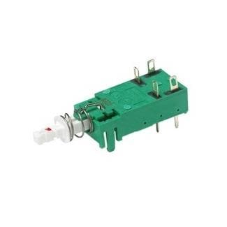
with a latching switch underneath, something like one of these:

ne18_series_new_SPL.jpg


I'm having a hard time finding the button part. I'm thinking of something like a 10mm diameter aluminum cylinder, maybe 15mm long, chamfered at one end and anodized black or clear. But I'm coming up empty handed -- all I can seem to find are all in one panel mount switches.

Is this something I should be able to find online?

BTW, adapting the button to the switch shouldn't be a problem since I have a nice 3D printer and know how to make nice parts with it.

I've considered going down the MacGyver route and buying things like modern drawer pulls and cutting them up to make what I want, but I have a feeling what I want is already out there. I just don't know what to search for.

Any ideas?

Regulated PS for Single Ended?

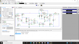
A friend of mine led me onto a PS that i thought was innovative, and pretty bullet proof, it was basically a traditional zener stabilized supply, with the exception of a CCS feeding the zener string with an interesting low pass filter which fed the pass device, a Darlington pair, the output noise figure i obtained in spice was around 1nV/sq.rt.Hz at 50Hz! could that be??? So I decided to use the same arrangement using a feedback design, and came up with similar results. Please ignore component values, Im also using a 6080 instead of a 6L6GC, I will reveal those later if this thread goes anywhere.

Attachments

  • Screenshot (28).png
    Screenshot (28).png
    120.4 KB · Views: 207
  • Screenshot (29).png
    Screenshot (29).png
    177.6 KB · Views: 201

PCB socket heat clearance

I am currently building a small tube amplifier for headphones using PCB socket mounted 6AS7 and 6SN7 tubes. my question is, how much clearance should i have to nearby components in order for them not to be affected too much by the heat from the tubes?
The sockets are ceramic and the tubes themselves will be on the outside of the amplifier chassis, and the PCB is standard 1.6mm 4 layer FR4.

300B BIAS

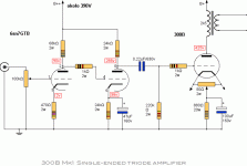
I am working on the Walton 300B amplifier. I want to change over to fixed bias. I have constructed the power supply and control but have seen the negative voltage hooked up to the 220k resistor. The resistor is disconnected from ground. I have also seen the negative voltage is applied directly to the screen. Any suggestions would be appreciated.

Attachments

  • post-10133-0-70233800-1340985286.gif
    post-10133-0-70233800-1340985286.gif
    18.2 KB · Views: 781

Kolinummi concept for reducing crossover distortion implemented on Blameless

Kolinummi concept for reducing crossover distortion implementable on Blameless

I decided to create a new thread to specifically discuss the Kolinummi error correcting output stage reviewed in this thread. The second page of the thread references Kolinummi and the Benchmark amplifier. Kolinummi provides references all the way back from the 1980s on amplifiers with error correcting output stages, so Benchmark may have a new implementation but it is not a new idea.

Kolinummi proposes taking the difference between the center of the drivers and the center of the output stage voltage and superimposing the opposite voltage on the input. The mechanism they use is to feed this back as a current through the VAS, but they use a somewhat unconventional VAS stage.

I first simulated this concept by imposing constraints in LTSpice and it was promising, so I went on to figure out how to practically implement it in a "Blameless" style amplifier. The implementation I developed was to take the error using a long tailed pair, and then inject the error current into the inverting input of a VBE multiplying voltage reference. The VBE multiplier is nominally at 2V, and can swing +/-1V to support error cancellation. The method works beautifully.

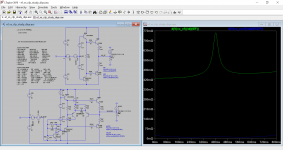
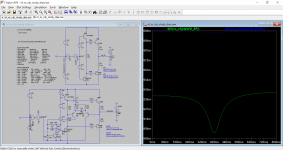
Attached is an LTSpice simulation comparing an emitter follower stage biased to 20mA and an error cancelling emitter follower stage. For the first plot, I made a current injection of -3A to +3A over 1 second to find the apparent output impedance versus current. For the second plot, I swept the input voltage from -10V to 10V over 1 second to find the voltage dependent gain.

I made similar analyses (not shown) for CFP and Renardson output stages, and they are not as attractive.

I hope this is useful to some. Let me know what you think. I added a capacitor across the LTP and the VBE multiplier to better control the inverting error amplifier impedance at high frequencies, but I don't normally see these elsewhere. I also used a CFP style VBE multiplier to improve its gain linearity, but a simple one may also be suitable with a slight change in resistance to adjust the gain.

Attachments

  • ef_vs_cfp_study_diya.asc
    ef_vs_cfp_study_diya.asc
    8.9 KB · Views: 141
  • vo_i.png
    vo_i.png
    108.3 KB · Views: 1,085
  • vo_vi.png
    vo_vi.png
    93.9 KB · Views: 1,101

About to take the ESL plunge

Hi,

I am a somewhat experienced speaker builder, building/designing several sets of conventional loudspeakers (including my most recent set that uses an active crossover).

Been getting the speaker building itch again and decided I would like to try a set of ESL's.

Just started doing my research on this and as such been reading Ken Seibert's and Jazzman's sites on their projects.

I'm looking to do the wire stator version. I would like build a full range version (or at the least get good, flat response down to 80hz) but not sure what size panels I would need to achieve that.

Just wondering if anyone has any advice for me as a newbie to ESL's?

How flat is flat enough? Frequency response SPL

Hello guys,

This is my first post so feel free to give advise.

I'm working on my first project where I'm building a bluetooth speaker but I have some questions about vituix and my frequency response. I've been thinkering with this for a few days now but I don't know how flat the responce should be. Some people say it shouldn't be actually and that you need some sort of happy smile in your midrange. So if possible I'd like some advice on this. And another thing was that I'm not sure how to implement my enclosure in vituixcad. I recon the enclosure dimension and volume will have an impact on how the speaker sounds. In the picture below you can see my designed crossover. I am looking at the Dayton Audio TD20F-4 as a tweeter and the Dayton Audio DSA215-8 as a midbase. My goal is to achieve a 100watt-ish setup (Im thinking of getting the TDA7498 amplifier)
spl.png - Google Drive

Hopefully I've given enough and not too much info.
Kind regards

A note about ARTA audio analysis software

I've been looking for a good spectrum analysis tool that wouldn't break the bank. I found ARTA (Google it). Its demo mode is very complete and its cost is also quite low, especially considering it phenomenally rich set of capabilities.

I've been looking at oscillators and THD. ARTA can compute THD as the actual RMS value of the spectral multiples of the input signal, and also can compute RMS THD+noise, which includes everything. ARTA's precision and set-up choices are just wonderful, with support for up to 192kHz sampling and whatever the amplitude resolution of the ADC is. Of course it also has a very complete suite of generators for doing THD and IMD -- these I haven't tried yet.

I used a first-generation Griffin iMic so that I could get the ADC close to the DUT -- my computer is across the room from the test bench and I didn't want hum from long cable runs. I set a couple of breadboarded oscillators to 1kHz as read by the frequency counter in my HP 3458 DMM. Then I measured the THD only with ARTA. The readings were over 10X more than I expected. I was really unhappy with the result. Then I decided to change the frequency of one of the oscillators. ARTA immediately showed that the iMic was putting out spikes at exact 1kHz intervals -- and at 3.8kHz out, the breadboard oscillator measured around 0.005% THD, about the limit of the iMic's capability.

When I hooked up a long shielded cable to the oscillator and my on-board Intel HD Audio line-in connection, the THD dropped to 0.0018% with a 400Hz HP filter enabled in ARTA. That's good enough for my purposes for now.

I really like the aRTA suite of measurements -- I just wish it would run on the Mac side of my Hackintosh instead of the PC side.

BGW8000 amp any comments?

Hi All

I am looking for some comments advice on a recently acquired BGW8000 power amp.
I am looking to use it as a sub woofer amp in the near future.
In short its supposedly abt 225w per channel into 8ohms
and I believe was more aligned to PA type use in the past.

Looking at a couple of issues:
1. It works and works fine...

2. Turn off thump (not turn on) - at turn off there is a loud pop from one channel only - I am looking to hopefully find the cause. (it may be part of the trait of the amp - I dont know)

the pop is immediately at turn off and is loud enough to cause concern as well as illuminate the "overload" LED on the front panel 1 channel only.

I wonder if it may be some arcing of the power switch..? causing the issue

I have reviewed the schematics and see that in the German version there is a cap across the transformer primary - being down under I assume that this cap may not have been installed ..


I have not yet opened the amp to confirm.

I notice that there appears to be essentially nothing on the forum on BGW amps...?

I am also looking to replace the rather noisy cooling fan..no dramas there.

I also notice ton the schematic that there are no fuses on the supply rails ....
I wonder if some should be installed...? Didt he old PA amps have supply rail fuses generally or were they avoided so as to not have a amp failure during live concerts- i- built tough...

So in short :

Any ideas ?

Why the pop? and why only one channel ???

My old Phase Linear 400 from lifetime ago used to have a bad case of flatulence as the caps powered down (i also had an outboard capacity bank on the Phase 400 to the tube of apprx 80KuF)

I've been trying it out on some of B&W DM4's - and it essentially sounds fine - though playing Stevie Ray Vaughn's "Tin Pan Alley" at a useful level (not what I would call excessively loud at all) causes some stress on some of the explosive guitar transients. the amp was not sounding like it was clipping but rather the speakers were saying to turn it down a little.


Last time i heard a BGW was a 750 model probably in mid 1980's and it was unsuccessfully trying to destroy a large pair of JBL studio Monitors at a HiFI show

The SPL meter they had on hand was reading up to 115dB from memory...


All comments and suggestions gratefully received.


Cheers from down under

Not quite HiFi-Radio Transmitter Modulator.

Working on the audio portion of my new amateur radio transmitter, it's basically a 70W class AB1 audio amplifier so I figure I'll let the audio guys have a look and see what improvements I can make. Radio guys are generally very securely in the "that's good enough" range of audio, but many times it just isn't and causes problems later.

That said-this is not a hi-fi design! Once the basic concept is established as not immediately going to melt into slag (the circuit presented here does not and actually works OK at the 45 watt power levels I've tested at) I need to limit the frequency response. I don't have a big enough 10K ohm resistor to properly load the secondary winding beyond 45W for more than a few seconds at a time.

gF8zgp1.png


Now, even though the desired frequency response is 100hz-10Khz, I've made little attempt at limiting the bandwidth so far. I am very open to suggestions on:

How to limit the bandwith, restricting it to 100hz-10Khz range
How to best apply some negative feedback around the whole amplifier. I've never been particularly good at making this decision.

Now, for the details:

The 807's are running 600V anode and 300V on the screens, and -32v fixed bias on the grids. They can provide a maximum of 72W of power to the modulation transformer primary, and operate in class AB1...lots of class B but still AB1. Plate dissipation is not being violated at the idle conditions, and short of a key-down single tone test for tens of minutes (not realistic) they'll be fine.

The modulation transformer will provide between 8.4K to 9.1K plate-to-plate load for the 807's. It was actually designed for a military transmitter that used 807's as the modulator tubes. The operating point was taken from the original schematic and backed off a bit.

The 6BL8 input circuit is a very nice low-distortion design modified from an RCA 50W audio amplifier but it was designed for a 25v output swing. I have not gone through and checked the distortion at the 32 volt output level nor made allowances for the increased drive needed.

The modulation transformer is as follows:

807's drive a 8.4K centertapped primary winding

The secondary winding is a 10K winding designed to carry 130mA of standing RF current.

The tertiary winding is a 1000 ohm centertapped winding that provides modulated screen supply voltage from the centertap to one leg, for the RF final. The other half of this winding could be used as a negative feedback source, but it will be biased at +250 to 300v, with a voltage swing of 206 volts peak-to-peak.

Thanks any suggestions!
Quick question about diode symbol on PCB

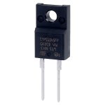
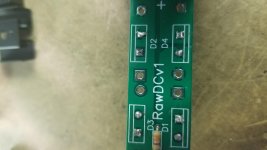
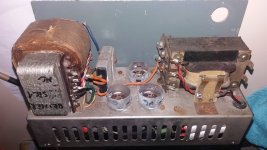
Hi all. I am populating a PCB today and ran into a problem. I have to mount 4 on these on this PCB but don't know how to read the symbol to ensure the right direction. I've spent an hour looking on Google with no luck. It is 101 degrees out and I'm working in the garage so I don't mind the break.

Attachments

  • s47-3662p01wl.jpg
    s47-3662p01wl.jpg
    22.4 KB · Views: 142
  • 20200719_171401.jpg
    20200719_171401.jpg
    440.5 KB · Views: 149

WTB Emotiva UMC1 parts

Hi ,


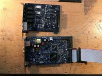
A couple of weeks ago my beloved UMC1 died .Everything functions , but no sound . I took it apart and narrowed the problem down to the audio board .
I bought a Denon AVR-X3500H .sound wise comparable , but I miss the flexibility . I would love to repair the old Emotiva , so if anyone has a spare audio board or a broken one with other problems please let me know , so we can work something out .


Thanks @ Cheers,


Rens

Isobaric "push-pull" 4 x 8" for guitar/bass

Just for a fun DIY project I am going to build a 4 x 8" cabinet to use with guitar, and maybe even bass. I have four cheap 8" drivers laying around. My goal is to get the four speakers into a relatively small space, and get as much in the 40-80hz zone out of them as I can. I guess I should have two of them facing out for better hi-mids, since it's not strictly a sub.

Could someone recommend which isobaric arrangement of the drivers might be a good way to go, for a simple design? Input appreciated.

Buffer Power amp.

Anyone know of a simple enough circuit that acts as a power amp for a power amp? i.e. A load buffer (current dumper?)

i.e. What i want is a power amp that has 1x to 2x voltage gain that it accepts 10v to 80v inputs form other power amplifer and drives the load (basically acts as a load buffer for the signal amp).

In other words lets say I have an integrated amp which sounds awesome at 8 ohm loads but like crap on 4 or 2 ohm loads... that I connect it to this supposed buffer amp that drives the load using the integrated amp as it's pre-amp....

It will basically be an output stage with 1 or 2x voltage gain (no need for input diff/ VA stages hopefully)...

Any ideas?

Anyone recognize this old amplifier Kit?

I got a couple of these 15 yrs back from eBay .... I now have some time to work on them. Wondering if they are worth it.

Recall them being sold as 80/wpc (8ohms)

I hooked up some wires and they work, but they have 3 IC’s near the front end, one of which looks like a protection IC that will not allow the relay to engage. I’d prefer to use that circuit, but it might need a separate psu... I cant tell.

Some pics to help identify.

The output’s are c2581/A1106, just a single pair... seems a stretch for 80wpc.... I tested with 63vdc rails and it played all the way till clipping without a mishap....

Attachments

  • 924499A9-3457-42B1-997E-0C9F69D213CB.jpg
    924499A9-3457-42B1-997E-0C9F69D213CB.jpg
    931.2 KB · Views: 400
  • 3B848F46-C962-473A-9424-311517B03CC2.jpg
    3B848F46-C962-473A-9424-311517B03CC2.jpg
    485 KB · Views: 380
  • 7DCFAFB4-38BD-4388-8343-EE773CE1E75E.jpg
    7DCFAFB4-38BD-4388-8343-EE773CE1E75E.jpg
    524.1 KB · Views: 369
  • 8CE48009-0EAB-4AE6-9A3F-5349F2425912.jpeg
    8CE48009-0EAB-4AE6-9A3F-5349F2425912.jpeg
    915.8 KB · Views: 367
  • 2E315720-2F64-4085-A173-520A3D2D5A58.jpg
    2E315720-2F64-4085-A173-520A3D2D5A58.jpg
    589 KB · Views: 365

How to get started in DIY amps?

I am just starting to get into building amps. I don't know much of the terminology, and how different components affect the sound, and I would like to understand more of the material I am reading. If anyone could recommend some resources to learn more about amps and how they work it would be greatly appreciated. Resources on how to get started designing amps would also be very useful. Thank you for reading!

Digitech AA-0481

Hi Everyone,

I have a Digitech AA-0481 amplifier (originally sold by Jaycar (New Zealand and Australia). It's rated at 300W into 8 ohms (no mention of 4 ohm support). It has quite a hefty output stage (6 x 2SA1943, 6 x 2SC5200).

Anyone know if a service manual (or just schematic) is available for this or something else equivalent?

Please note; this Digitech is not the same as the DigiTech guitar effects people.

Many thanks

Andrew

Looking for some free WAV to FLAC Batch Conversion Software

I originally ripped my CD's to WAV for storage and to MP3 for playing on portable players.
But I now realize I should have also ripped them into FLAC as for playing in my house.

The WAV files are in directories (Artist\Album\Song) so I would like
some software that will pick up the path and use it to tag the FLAC file.

The alternative it to re-rip them but I would like to convert them if possible.

I'm looking for something fairly simple since I should only need to
do this one time since going forward I will be ripping FLAC as well.

Thank you

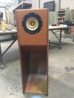
Pics New Lowther "Alfredo" horn using CNC'd Birch Ply

Looking forward to starting this exciting new project, modernising the Alfredo design. (Alf Lepp (RIP) was the designer, and the plans are in the public domain.)

The unit is approx 1150mm tall x 580mm deep.

It should be weighty given the solid sections of CNC'd ply.

Cues taken from recent Tang Band BLF project with exposed ply....plus my C-Horn.

I'll also be including a new Lowther baffle 'ring' which is machined in MDF, which was tricky to create as Lowther uses an off-circle shape.

Driver of choice, PM7A (Alnico).

Andrew

Attachments

Kitchen Cabinet Speaker

We have a Pure Evoke 1 DAB/FM radio in the kitchen and the sound from the the built in speaker is not up to much.
The radio lives near a tall larder unit made of 18mm faced chipboard with slide out wire baskets and containing dried and tinned foods. For a quick and easy solution I was thinking about cutting a hole in the side of the cabinet and fitting a HiVi M3N or similar and driven by a class D amp.
Is this likely to work?

Lance

Newbie Gainclone Problems (LM3875)

This is my first post. I apologize in advance for my extreme ignorance.
I recently bought an amp that I thought might be a shortcut to gainclone fun. See first picture. It cost less than a bare toroidal from partsexpress.
My goal is to build something like what's in the second picture.
I don't yet read circuit block diagrams well, so I hoped that by starting with a complete amp, I could just connect up an eBay input selector and be done (in a new chassis).

However, this amp has some hiss, and when I check the voltage at the amplifier, I read 45.7 volts. Am I right that this is too much power? The transformer has 30 volt secondaries.

If I'm right, should I try to modify the psu to drop the voltage? Or buy new amplifier boards? (e.g. ebay mx50se)?

Thanks for your help, and my apologies if asking questions like this straight off is not ok.

Attachments

  • DSC00252.jpg
    DSC00252.jpg
    783.8 KB · Views: 546
  • DAL3886INT_6T__46364.1426966809.1280.1280.jpg
    DAL3886INT_6T__46364.1426966809.1280.1280.jpg
    46 KB · Views: 515

Wrong transformer

In my limited electronics design experience, I've been doing digital for decades. I've just acquired an interest in tube amplifiers, and analog circuits in general. As all of you know this is far more intricate than digital.

One easy thing for someone like me is to forget about PP vs RMS. I ordered a Hammond transformer from Digikey that, with a CLC without load outputs around 530Vdc.

I was originally modelling around 375Vdc for B+.

I was planning on working with some 12AX7s and KT88s. I know the KTs can handle it, but definitely not the 12AX7s.

I've bought Merlin's and Morgan's books and understand the predicament I'm in, particularly around the DC load line and if the cathodes aren't heated up, and voltage drops that come with that. The KT88s should be fine but the 12AX7 would not appreciate a 530Vdc potential.

I'm also using silicon diodes as a rectifiers, so there is no heat up delay.

I basically bought the wrong transformer, I meant to get one at a much lesser volt.

I realize there are many ways I can approach this, including just buying another PT, setting up a delay circuit, etc.

In my mind, based on what I've learned, I'm already screwed. A 12AX7 has a max plate voltage of 300V, assuming no current flow. With the PS I have I'm far in excess of that, no matter what I do.

I'm just wondering if anyone can suggest the most economical and safe way to move forward, just to get by, while I refine my schematic, without buying a new PT. I've already learned(re-learned) a few lessons, which is why I'm asking for more knowledge.

Bottom line - how can I continue testing with this circuit and guarantee that I won't overvoltage my 12AX7? Did I blow it with my ill transformer choice or is there a way around it?

FS: DIYINHK AK4497 DAC Boards

I have realised that I am not going to get around to assemble this dual mono DAC that I had planned so I am putting these up for sale.
These are 2 no PCB's as per the link below that I build a little while ago.
768kHz/32Bit AK4497EQ DAC, I2S/DSD input - DIYINHK
Selling both boards together for half new price at £99 excluding PayPal fees if appropriate and postage.
6E479551-90FD-4A20-9705-BC60A6114231 by themystical2012, on Flickr
996D75FA-3BE0-474D-AE7A-C7641E5A6B51 by themystical2012, on Flickr

3 way with TC9FD as mid -suggestions

Have been reading a lot of good reviews about Peerless TC9FD as a mid and about how the voicing is perfect and response is flat .
I am interested in a 3 way with TC9FD as a mid with a minimum of 8-10 or at the max a 12 inch woofer in a relatively small enclosure . Can some one point out any plans or builds which I might have missed ?
I did read a 5.5 inch tangband sub build , but the goal is to have an all rounder with a decent spec woofer and a tweeter implementation . The target cost would be under 300 USD for the drivers .
I am not good with speakers and crossover design so I am at this point of time looking for open source builds .

Any suggestions ?

Questions regarding designing a parafeed line stage and the LL1930 transformer

Hi, I am new to the hobby and have been working my way through books and articles and learning to use LTSPice.

I am interested in designing, simulating, and building a parafeed line stage and have been looking at the Lundahl LL1930 transformer for parafeed line stage applications. I was wondering if anyone has built a line stage using this transformer.

The transformer has two primary windings and two secondary windings with a 5.1 : 1 or 11.6 : 1 turns ratio and. Static resistance of each primary is listed as 610 ohms and the static resistance of each secondary is listed as 16 ohms.

I do not see a listing for the primary impedance however, and I am wondering what tubes are recommended for use with this transformer.

More generally, I would also be interested to learn about the thought process you use when designing a new amplifier/preamplifier from a systems perspective. Do you begin with a circuit topology and then pick a transformer and work through the circuit backwards optimizing as you go, or start from the source and work towards the output, or use another strategy altogether. Many thanks, Martin.

Ian's Ultracapacitor Explore PLUS - build thread

This thread is for the owners of Ian's excess PCBs from post 163 of his original thread Develop ultra capacitor power supply and LiFePO4 battery power supply.

The schematics were shared in post 187.

I started a Project in Mouser: Ian Ultracap PSU v1. I chose the smaller-capacity alternative as the ESR was lower too and I'm not sure I'd need that much capacity anyway. Please adjust the project accordingly, if you need the higher-capacity alternative.

The outstanding part is the LT3042 board. I will update this post when we agree which one to use. So far, there a few ready-made eBay alternatives (though with LT3045 instead and Ian warned me that we should make sure the current is limited to 200mA) and some PCBs were designed by diyaudio.com members and can be ordered from PCB manufacturers.

The list will grow here:
1. PCB: LT3042 LDO Regulator - PCBWay.
2. PCB: Ultra Low Noise Linear Power Supply, using LT3042 - OSH Park.
3. LT3045-78xx Ultralow-noise (0.8µVrms) linear regulator 0V-15V, 0.5A, 78xx Layout - eBay
4. This one is also pin-compatible, but it doesn't look as good as the one before it: LT3045 3.3V 500mA 0.8uVrms Ultra Low Noise Linear Voltage Regulator Replace 7833 - eBay

Technics SE- A900S no speaker relay click

I have been asked to have a look at a friends amp
the amp powers on and the vu meters light up but no relay click
the operation light is not lit
you can hear the big power relay click on and off
the main power supply is working both caps test ok
i have had the board out and checked all the caps replaced two which where out of spec
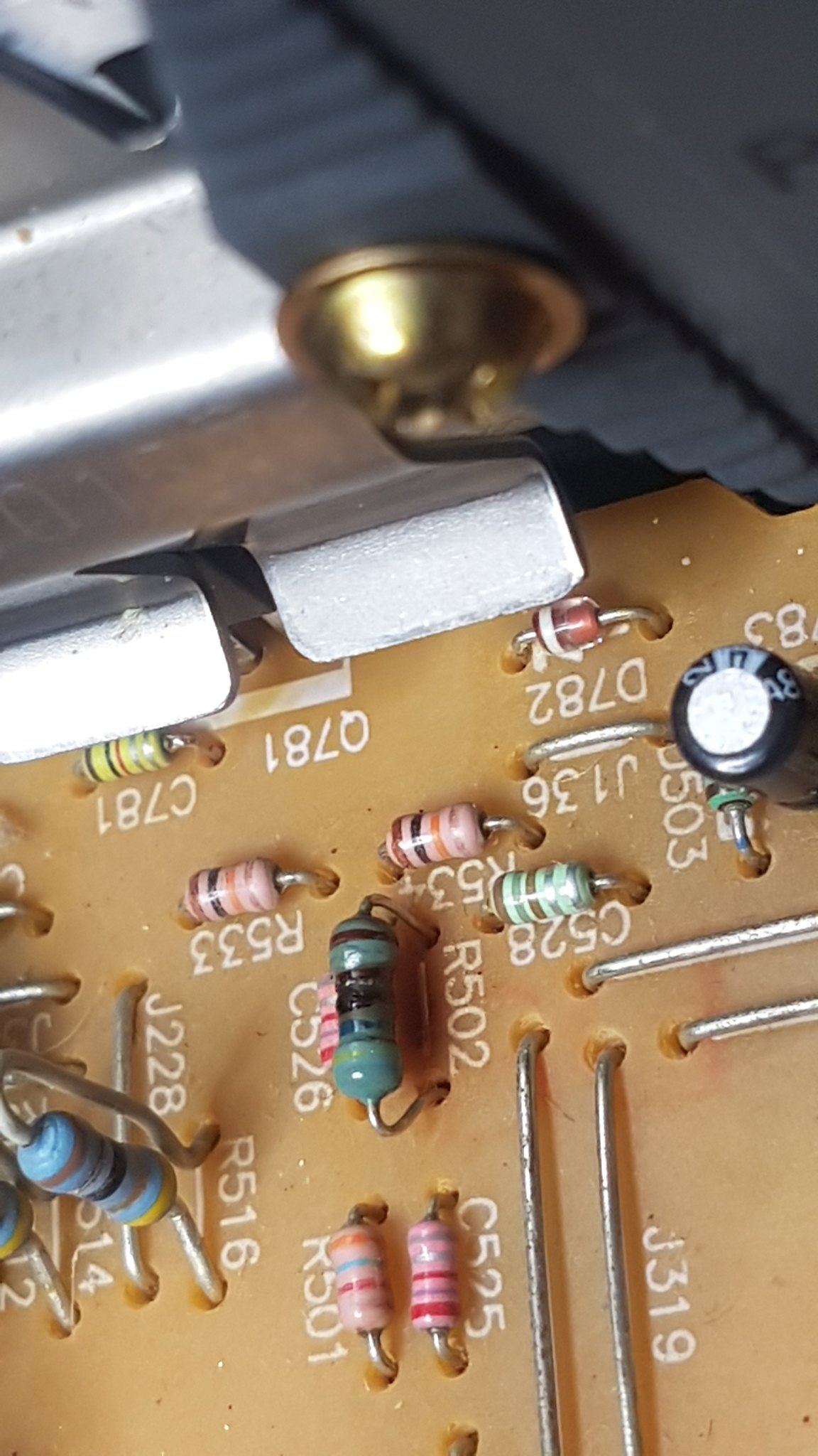
replaced caps C502 / C504 100uf 6.3v and R502 which was burnt
put it back together and still the same but when switched on R502 gets very hot
i have included the manual
TECHNICS SE-A900S SERVICE MANUAL Pdf Download | ManualsLib

20200718_153233 by glenn jarrett, on Flickr20200716_152600 by glenn jarrett, on Flickr

MLSSA on linux?

Are there loudspeaker measurement systems based on MLSSA principles around? For measuring inside it might be better then swept sine.

I had something like that running on DOS with an interface connected to the printer port years ago. But I guess now using the sound card might be a better option 🙂 I'm happy if I can do frequency response, impulse response and waterfall.

Hello from Germany


Hi, I'm new to the Hi-Fi world and I love to learn things. I've been considering investing in a Hi-Fi system for my desktop and my living room alike. I figured: why not do everything by myself? I have time, am patient and unequivocally wish to enjoy the process of searching for the right parts, understanding how it all works etc.

Any advice for a neophyte like me ? 🙂


I only have a pair of Focal Spirit One S Headphones on my desk... hopefully it'll soon change with your recommendations (i.e. DAC, AMP, Speakers...): I'm open to any suggestion. Where should I start ?


Thank you for reading this!
light up tubes without signal

I know this might sound strange, but I want to power tubes only to light up, I don't need to amplify any signal.


I have two cheap EL34, from the datasheet

Filament Voltage 6.3V
Filament Current 1.5A


A) I presume that in order to power both of them I need a transformer with 6.3V secondary and 3A in total. Am I correct?

B) Is AC ok? Or, do I need to provide DC voltage?

C) I have been told that doing this way the tubes won't last that much? Is this True? How long they can survive?


I know this is kind of strange, but I need this to make a terrible joke to a bunch of bad audio-friends.

DIY Amp Guidance

I am very new to the idea of building an AMP. I have an old metal toolbox from my Grandfather that the electrical union gave him with a nameplate. I just can’t bring myself to throw it away. So I have this idea of making an amp out of it. The tool box is roughly 18x8x9 in size and is a metal Craftsman.

I found a MOD 102 5 watt amplifier kit on Amazon. I would like to add 3” or 3.5” speakers to the front of the tool box, I may be able to get 4” in but it would be tight, and start detracting from trying to keep a more nostalgic look.

I have no idea what I am getting ready to step into. I am very handy and the project itself does not scare me. I just haven’t done audio before with such a specific purpose/outcome. Success would be a unique conversation piece that I could plug into and get a decent sound out of to strum around with an electric or acoustic-like a little practice amp.

All guidance and direction appreciated. Thanks in advance

Jordan Eikona as a mid

Just curious, anyone used the Jordan Eikona as a mid in a 3 way. This lauded as one of the best full rangers and can dig to 40hz in the right box and touted to have “holographic imaging qualities” (puts the BS Dictionary away!).

Looks like it could do 150hz to 5khz in a 5l sealed box supported by a 10” (sub) woofer (e.g. SB29NRX75-6, Scanspeak 23w4557, Dayton RSS265HF-4, L26ROY) And a small ribbon, 0.75” tweeter Or Fostex Supertweeter (e.g. Neo CD1.0, OW1, T90a).

However, not seen any off axis measurements so a bit of an unknown.

Thoughts?

Speaker for analogue synth

I'm playing around with analogue synths and I'm considering whether or not to build a dedicated speaker (or two). I figure there have got to be a few people here who have done similar things.

I have a few requirements. If im going to go to the trouble then it should be able to handle practice volume with other musicians. It should be able to reproduce low notes in the range of 20hz (give or take depending on whats realistic), and it needs to be able to reveal the appealing timbres and complexity of a genuine analogue synth. I'd like to keep this under apx $200/speaker but thats a ballpark.

Id prefer not to build a horn but I'm open to suggestions.

Amplification will be some sort of off the shelf thing like a behringer or similar. Active is an option or I can design a xo. I have measurement gear.

Left to my own devices I would likely look at Eminence's 12" pa drivers and a compression horn but I was wondering if anyone has used something like this that they were super pleased with.

DIY full range speaker

Hi i am trying to get the knowledge and build a simple full range speaker floor standing, something very easy (no spl metering , no crossover designs etc) . I don't have any wood work skills or a friend so i will go to a wood work shop with the dimension of my floor standing dimension from a cabinet speaker calculator for the specific Full range driver .

Is there any links related to a such a simple project ? Because every link i found was to complicated for what i am trying to do .

For example i want to buy a Tang Band or seas or scanspeak driver hook it up to a floor standing sealed cabinet (made by the wood worker) with the right VAS lts , damp the box with dumping material and then connected the speaker to a Amp and play some music .
I currently have speaker, POLK AUDIO T50, so i will have some reference of the sound .

Could a such simple project end up with a good sounding experience overall ?

Need assistance on this resistors found in KAV-300IL

I bought and old KAV-300IL. Open up the amp and found this repairs done. Its 2 x Dale 5ohm resistors soldered across the 10ohm AMD resistor. I don't quite understand whats it for. Because 10ohm dale and 10ohm SMD resistor in parallel would become 5ohms. Found it across 3 10ohm SMD resistors....


would need some assistance on whats it for??

Attachments

  • resistor.jpg
    resistor.jpg
    488.3 KB · Views: 184

Do Brands of Capacitors Matter alot for Power Capacitors?

I am planning to replace the 8 x 6800uf 63V capacitors on my amp as they are 20yrs old.....


I am curious if brands of capacitors matter. The original ones are nichicon ones. But if I use brands like cornell dubilier, Kemet, united chemicon, will there be any significant difference in the audio?


I do understand mundorf is good but its very costly so I am looking for alternatives.

miniDIGI Jumper config for 1 miniDIGI + 2x miniDSP

Hello.
I don't know if this is the proper forum, but let's try:

I do have a stack with 1 miniDIGI board + 2 MminiDSP balanced connected following the Application Note "Configuration of 1 miniDIGI + 2 miniDSP" to buils a 4 way crossover

What I need to confirm is the Jumper Chart for 1 miniDIGI + 2x miniDSP stack because i think thet the one ath miniDSP web is wrong or, at least not the proper one for my application.

this is what I did:

Minidsp 1 (left CH) SLAVE
Minidsp 2 (right CH) SLAVE
Minidigi MASTER

Does I have to setup J1 at miniDIGI like a 2 way setup??

An externally hosted image should be here but it was not working when we last tested it.


Picture might not be cclear, but the miniDIGI setup is like MASTER

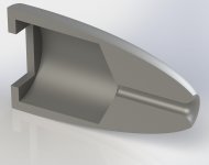
Bullet-shaped BR

I was CAD doodling yesterday and came up with a rather sleek-looking bass reflex for the Tectonic TEBM36S12 that can be printed in a single piece (though it will need splitting up to fit out). The part I can't quite figure out is where to put the connectors and what form the stand should take. For the stand, a profile that joins on at the front would allow it to be printed with the speaker without using supports. I would really appreciate examples of anything similar which I could s̶t̶e̶a̶l̶ adapt for this design. The only thing slightly similar which I could find is the top half of the B&W Nautilus.

On the driver front, could anyone suggest a decent sub-£100/pair driver that's less than 100mm outer diameter? I'm not set on using the Tectonics, I just had them to hand for another project and had the parameters plugged into Transmission Line.


Thank you.

Attachments

  • BRSq CS.JPG
    BRSq CS.JPG
    222.5 KB · Views: 242

Arcam AV50 Receiver red power LED

Hi everyone, i have a AV50 prologic receiver which just powers on and the power led goes from amber to solid red, there's no flashing red. There is nothing on the LCD display. I've also tried to press different buttons to "wake it" but no response.

Is there someone who knows what this solid RED led means? I've emailed ARCAM and they actually said they don't have a specific fault for this. I'm requested a service manual from them.

Unforuntately i don't have the remote anymore, so can't do any troubleshooting with that.

Thanks in advance.

Guitar amp with 2 x EL86 push-pull

For some time now time i've been planning to make a guitar amp with 2 x EL86 (= 6CW5) push-pull.

I looked at the schematic of the Hagström 620, which has 2 x EL86 in push-pull but i do not trust the schematic i could find on the internet. The screengrids are being fed straight out of the rectifier section, while the anodes are being fed from a point after a fuse and a resistor. I can hardly believe this to be right. If that fuse would blow, it would probably take the EL86's with it.

Because i allready have built a guitar amp with EF86 + 2 x ECL86 pp which is based on the clean channel of the VOX AC15, i now want to build a similar amp with EL86's, so i can hook the two amps up in stereo.

According to Philips datasheets, two EL86's in pp can produce 18,5 Watt at 4,5 % distortion, with Vba = 250 V and Vbg2 = 200 V.

Because the current for the screengrids varies a lot between no signal (2 x 2 mA) and full signal (2 x 13 mA) i plan to stabilize the screenvoltage with 2 ZZ1040 voltage stabilizer tubes.

I want to use the E92CC as the phase inverter because of the chassis i plan to use. The schematic for the phase inverter comes out of a Philips datasheet for the ECC40. Not exactly the same tubes but i am pretty sure it will work with an E92CC.

So here is my plan. I am a bit unsure about the 100K resistor that is connected to the point where the two ZZ1040 are connected to each other. I think this resistor is necessary for making sure that both ZZ1040's will start up.

Any suggestions?

Attachments

  • Hagström 620.jpg
    Hagström 620.jpg
    192.3 KB · Views: 525
  • Schematic.png
    Schematic.png
    30.7 KB · Views: 539

Suggestions for complete newb - PC/desktop speakers?

Hi all,
I've done a fair bit of searching and reading, and all this sounds more like algebra than English to me, so I hope this isn't a lost cause.
I'm trying to get some help to repair my old Logitech Z-5500 PC speakers in another thread, and something someone said kicked off a curiosity bug in my head about speaker building.
So I started researching and now I really want to build myself a set of small deskop speakers to replace the Bose bookshelfs that I'm using now.

I really like the Needles, I just don't have the room for them in my office, and they will need to sit on my desk, not on the floor.
I have a decent workshop, so the actual box construction shouldn't be too hard, and I can usually solder without burning down the house.
My problem is that I have not a single clue where to start in regards to driver selection or enclosure design, plus I'm cheap (read: poor) and don't have a ton of extra time for a lengthy build.
Where should I start? I'm looking for something that will sound as good or better than my Z-5500s with these Bose bookshelf speakers (sorry, can't find a model number) serving as the left/right channels. I'd also like them to be smaller than my current boxes, which are about 15"tall x 10"wide x 7"deep.
I'm driving all this off the Z-5500 amp and sub, which I plan to keep unless there's a compelling reason not to?

Any advice appreciated!
-Mike

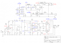
As simple as possible, no simpler?

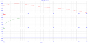
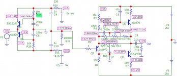
I'm fishing about for something to build with the parts i've collected and need a decent MC phono amp. After some research, i'm interested in this. Thanks to Richard Lee for the front end and an unknown Sony engineer for the back. Any comments? Improvements?

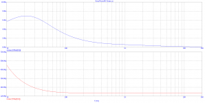
SonyPhonoMC-noise.png

SonyPhonoMC-raw_response.png
If i simulate an inverse RIAA circuit on the front, i get a mild bump around 30Hz and rolloff below and a very small rise at 20kHz, otherwise flat.

TIA, Rex

Attachments

  • SonyPhonoMC-Noise.JPG
    SonyPhonoMC-Noise.JPG
    126.9 KB · Views: 173

Yamaha P3200 - IC replacement

Hello! I'm looking for a suitable replacement (or upgrade) for M5238A input op amps in my Yamaha P3200 that I recently bought. It seem that both of them are fried. Will OPA2134PA work?
The amp will be used in my studio to power my main monitors (Tannoys), so if there is a possible upgrade I am into that!

I've attached the P3200 schematic if needed.

Attachments

XLR low pass filter between prepro and power amp

I'm not sure if this is possible (I'm a complete beginner) but is it possible to filter out frequencies above approximately 30khz between a preamp/prepro and power amp?

The prepro is listed as 560 Ohm at the XLR output
The power amp is listed as 47 KOhm at the XLR Input

This looks useful but I'm unsure which resistance to use or if it is even suitable:
Low Pass Filter Calculator
Projects by fanatics, for fanatics
Get answers and advice for everyone wanting to learn the art of audio.
Join the Community
507,921
Members
7,893,724
Messages

Filter

Forum Statistics

Threads
406,492
Messages
7,893,724
Members
507,921
Latest member
bedomes