Troels Gravesen SBA-941 Build

Hello everyone! So I have started to build Troels's SBA-941 (SBA-941). I have cabinets almost done and now I'm ready to order drivers and crossover parts.

Now the hard part is to decide how far up I want to go with crossover and driver options (SBA-941).

What are your opinions on how big improvements there are when moving to better caps etc? This is my first diy build so I have no idea how big differences in sound we are talking here because price goes up quite steep with these upgrades. I have the cash to layout for these if it's significant improvement.

1. SBA 941 - 3-Way Classic - TW29RN-B - Alumen Z - Silver Z + Drivers 1654 €
2. SBA 941 - 3-Way Classic - TW29BN-B - Beryllium - Alumen Z - Silver Z + Drivers 2079 € (+425 € to base version)
3. SBA 941 - 3-Way Classic - TW29BN-B - Beryllium - Ultimate version + Drivers 2659 € (+1005 € to base version)


Second question is what kind of equipment I should be looking to get most out of these. I'm aiming for music first but I'm also going to get surround channels for movies/tv. Currently I'm thinking of getting some AVR with preouts and suitable amp for SBA941.

And question number two leads us to my next build project. Any recommendations for center? For surrounds I'm probably going with some commercial speakers.

Worth it to remove damaged dust cap when "replacing" them?

I found a very dirty pair of NHT VT1.2's at the local goodwill type store for $50. I picked them up and had to replace a couple of crossover capacitors to get them sounding wonderful again! I was really shocked how good they still sound. All four 4" woofers appear to have had their 1.5" paper dust caps "fingered" and pulled back out multiple times. They are not ripped but look horrible with permanent wrinkles/divots. They can't be "fixed. So I ordered new 1.5" paper caps. I started removing the old caps with a fine tipped razor knife. The caps' paper fibers are very loose from all the in/out abuse they've received. The loose fibers mean the caps aren't gonna come off cleanly. There is a remaining fibrous ring where it was glued to the cone. The weight/mass of the paper cap that I removed was very, very light. I'm concerned that some of the fibers from cutting these old caps out will get into the exposed magnet gap/voice coil. Due to the caps' low weight/mass would it be safer to just glue the new caps over the old damaged ones? The other option would be to give that remaining fibrous ring a coating of something like dust cap glue to solidify the fibers, but wouldn't that add as much weight/mass as just leaving the old caps under the new caps. Btw, not replacing the caps is not an option. I want these to look like new again. Luckily the tweeters look perfect and the cabinet cleaned up very well!

DAC muting function doesn't work as it should issue

Hi All,


I have 2 DACs with the same issue, Orelle DA-180 and Maverick audio Tubemagic D1, when I use the optical or coaxial inputs and switch between tracks in my audio streamer I get a "hiss" noise in my speakers.
While using the Orelle DAC there is this noise then 3 seconds silence and then I can hear the muting relay clicks and then music, in the Maverick audio DAC there is this noise then relay click and music, there is no silence like in the Orelle.
There is no noise when I'm using the USB input in the Maverick audio DAC or using an external USB to toslink/spdif converter.
Unfortunately I don't have the DACs schematics and cannot find one.
Does anyone have an idea what can be the cause for it or what components on the PCB controls the muting relay response speed? it feels like the relay doesn't respond fast enough to the muting signal.


Thanks

DS18 PRO-FR9000.1 in protection

When I got the amp the first thing I found was a film cap burned apart at I think C112 which is connected between the two speaker terminals. I have replaced it with a temporary cap until I troubleshoot it a little more.

When I attempt to power the amp up through current limiting resistors, the only thing I find out of place on the 494 is pin 4 is above 3.5V and of course pin 9 and 10 are off.

If I adjust my power supply up a bit to ~14.8V to ~15.1V the amp will bounce in and out of protection. The amplifier's power supply will run enough to charge the rail caps to +/- 103V, but it never stays on long enough to get the +/- 15V on the ICs.

I only find a 10K ohm resistor between pin 4 and ground. I decided to take pin to ground bypassing the resistor. Upon powering it up, amp is still in protect, but pin 16 is now at 4.9V and pin 13, 14, 15 are now at 1.5V.

So something is dragging the 5V regulator down now before jumping the resistor it was 5V.

I think the 494 is damaged or is it still something else because pin 16 is now so high? It was ~2.9V before jumping pin 4 to ground.

Attachments

  • DS18 PS Driver Board.jpg
    DS18 PS Driver Board.jpg
    693 KB · Views: 137

New computer speakers (Tabaq TL)

So,

I'm a Dreamer, thinker and engineer. A theorycrafter if you will.
I like thinking about things, figuring them out into every detail.

Late last year I ran out of projects to fettle with and stumbled upon the Tabaq TL thread.
I read through it a few times. it was interesting how many different drivers that could be used.
it was interesting seeing the Tabaq TL design develop over time and how many people built it.

I liked how easy it was to build, and how well recieved it was and the performance/price ratio.

AFter some careful thinking I started looking at a design based on the Faital Pro 4FE32 8ohm version.
Since it was a 4" driver the design did not need the updated port.

After some fettling I realized that I could fit 4 normal Tabaq TL and one folded on a single sheet of 2440x1220x12mm


See image #1

I contacted a firm which makes furniture and they would cut out my design on their CNC mill. The mill head was 4mm he informed me.
He qouted me the price of 2200SEK to do it using Birch Plywood of BB/B quality. Which he stated was the best quality available. Any subsequent run will probably be cheaper. I can hand out contact details to the company if the original designer approves of it.

Right before I left on my vacation (about a month ago), I got a call to pick up the pieces. They looked good. one or two splinters on the edges.

Me and my dad made them in his workshop. Same workshop where we made the the Frugal Horns MK3.

I've now had them for a a few weeks, trying to break them in using a Volt +D amp.
I've decided on keeping them natural with the only treatment being some sanding using rediculous grit sand paper and a layer of matte uncolored vax oil.

I am rather pleased with both the sound and the the way the look.

Finally, I'd like to thank the creator and all of the people who contributed to the design.


PS, I apologize for the cable hell around my computer. : DS

Attachments

  • sheet_plan_5.png
    sheet_plan_5.png
    26.4 KB · Views: 162
  • WhatsApp Image 2020-08-08 at 19.41.40(3).jpeg
    WhatsApp Image 2020-08-08 at 19.41.40(3).jpeg
    117.8 KB · Views: 156
  • WhatsApp Image 2020-08-08 at 19.41.40(2).jpeg
    WhatsApp Image 2020-08-08 at 19.41.40(2).jpeg
    132.4 KB · Views: 161
  • WhatsApp Image 2020-08-08 at 19.41.40(1).jpeg
    WhatsApp Image 2020-08-08 at 19.41.40(1).jpeg
    105.2 KB · Views: 155
  • WhatsApp Image 2020-08-08 at 19.41.40.jpeg
    WhatsApp Image 2020-08-08 at 19.41.40.jpeg
    81.6 KB · Views: 161

New ideas for K-55 and PD-5V compression drivers

Radian, what you are arguing here has nothing to do with what we "discussed" together above, which was only focused on midbass compression driver, and how a 2" Atlas compression driver could be better in this range than a 4" or 8" more modern (and costly, and with far more R&D behind it) compression driver.

No this was the battle field you created. You just brought in the JBL 2482
wich neither is better than the modified K55 and is way more expensive to
obtain. What use was this for the discussion at hand.
The reason I introduced the K55 was that many people who have heard the
WE555 on the big WE horns report excellent sonics in the low region which
tells us that this driver is just very good for this kind of application.
I have yet to see any post that rave about the how excellent the JBL does
in the lower than 250hz region.
Dietmar did not specify the input to the modified K55. What he said is that
the the Line Magnetics 555 was not any better on paper, and that he has
cranked the volume up and he did not percieve any distortion or ill effect.
He has probably heard and set up more big horn systems than most dedicated horn lovers.

Here is a pic of the modified K55. Just a Peavey magnet structure glued
on with a little felt cavity attached to the vent hole.
Before is black and after the mod blue line:

Attachments

  • K55-mod-1.png
    K55-mod-1.png
    328.2 KB · Views: 1,454
  • K55 mod vs stock.png
    K55 mod vs stock.png
    221.6 KB · Views: 1,409

Pioneer SA-606

After 40+ years my 1,978 Pioneer component amplifier blew up a power supply thyristor along with 2 resistors a couple of weeks ago.

My amp was still using its original pieces so I decided to replace the blown parts, and since I was working on it, I decided to recap the whole circuit with Nichicon Audio grade caps for electrolitics, also I replaced high wattage resistors (1/2, 1 and 2 watts) with Vishay/Dale metal film resistors and also ceramic caps, some of Polypropylene dielectric (the ones I could find) and the rest with c0g/np0 dielectric.

Is there something else you guys recommend doing or replace on my amp? Any suggestions are well appreciated. Thanks for taking the time to read.

Have a great day.


SkyWay

Crossover REW Measurement for Urei 813C

I got some pretty emblematic studio speakers some time ago but never hooked them up. So first they needed some love, cleaning and such. They are 3-way, massive speakers, Urei 813C. So before connecting them to the Bryston 4B NPB, I decided to check the crossovers, look for leaky caps and such. I certainly did not find any clear offender by inspection or individual component testing, so decided to fire them up. The sound was pretty midrangy. The manual did say that the speakers are really sensitive to installation position, that is something to have in mind.

So decided to run a REW test, with the speakers connected, to see what type of curves they have. I am just tapping into the speaker terminals with a sweep. The results are attached. Some wacky curves going on. Tested the second one. Almost the exact same curves.

So questions have arisen: (bear in mind I am just starting to learn about speakers)

First, I suspect my measurement procedure is terribly flawed but,
If not that bad, then:

Are maybe those bumps trying to correct speakers?
Are those bumps normal if a crossover is measured like that?
Maybe crossover health is not that good?

Attached are pics and manuals.

Thank you all!

Attachments

  • 813C-L,R.pdf
    813C-L,R.pdf
    113.9 KB · Views: 221
  • IMG_20200728_020206813.jpg
    IMG_20200728_020206813.jpg
    390.3 KB · Views: 600
  • IMG_20200728_020152749.jpg
    IMG_20200728_020152749.jpg
    422.6 KB · Views: 525
  • IMG_20200728_020143950.jpg
    IMG_20200728_020143950.jpg
    585.1 KB · Views: 464
  • Rew 813C Cv.jpg
    Rew 813C Cv.jpg
    131.6 KB · Views: 502
  • UREI811C_813C_815C.pdf
    UREI811C_813C_815C.pdf
    1.7 MB · Views: 319

beginner crossover design

View attachment 862898Hi all
This is the second crossover I have designed and I think I'm having some trouble. Could someone take a look at my design and give me some advice. Ill also leave the manufacturer frd. and zma. files if you would like to give it a shot. I'm just a beginner and am not looking for really Hi-Fi sound just something to make it sound good. Thanks.

Attachments

TQWT with a Fostex FF165wk?

Hi there guys,

I want to build this TWQT. However, as it seems quite difficult to find a pair of Fostex FE 166e, I was asking myself whether the new FF165wk might work here:


I have set myself on a TQWT sporting a 6" drivers due to WAF and space-related issues. Not a very original reason to come up with, I know. I'll be driving them with a 2a3 SE amp. I don't want them to end up stored in the attic next to all my previous building DIY-efforts, so that's why I'm asking you now.

Any suggestions, mods or alternatives very much welcome!

A winter project :deer:

Regards,

Vincula

X bosoz boards

I have 4 sets of x bosoz boards partly populated. I had gotten them from another member and never tested or used them.

$20.00 usd plus shipping
Thanks,
Evan

Attachments

  • A66DB0F6-71D8-47E6-85F3-E26876F4DA82.jpeg
    A66DB0F6-71D8-47E6-85F3-E26876F4DA82.jpeg
    948.5 KB · Views: 191
  • E0C0A4A4-82B0-4070-A693-23F3A388C87E.jpg
    E0C0A4A4-82B0-4070-A693-23F3A388C87E.jpg
    831.2 KB · Views: 210
  • 7AC3322C-6938-470C-B50F-4745DAF8EE41.jpg
    7AC3322C-6938-470C-B50F-4745DAF8EE41.jpg
    999.3 KB · Views: 185

Denon DRA 685 receiver stuck in protection mode.

Hi. New to this great website and new to audio electronics.

I have a Denon DRA 685 receiver that won't get out of protection mode. After I push the power switch, the protection light blinks 8 times and then stays on. I also hear a click which I believer is the power relay. Thats it - no display, no sound,nothing.
Following the recommendation of another website Denon DRA-685, I replaced 2 resistors on the main board (R105 & R106), but that didn't solve the problem.
I am not getting the required "+15V" and "-15V" at test point CN1. I am getting .137V and .567V respectively. This is the same reading I am getting at the power regulator transistors IC1 and IC2.
I am getting the required 6 volts at IC 4.
To make matters worse, the service manual schematics that I downloaded from HiFi Engine are very blurry, thus I can't read the required voltages at different test points.
I am stumped.
Any help would be much appreciated.

Thanks

Crossover question - pre build crossovers?

Hi guys and girls

I'm working on my first project and have come to the speaker build ( going great ) - but have come to a dead stop.

Crossover!

As I have 10 thumbs and I'm not really happy about beginning to build a crossover from scratch - too much can go wrong when I'm doing it.

People are really good at showing why 2 and 3 way pre-build crossovers are crap, and I get it.

But if we look at a simple straight forward oneway crossover, what can go wrong?

https://www.soundimports.eu/en/dayton-audio-6000-lpf-4.html

Can they be used ?
Can you just wire them in series so they will split for bass, mid and tweeter?

My logic says

Crossover 1 splits the signal 2 ways
Crossover 2 takes signal from the first crossover and splits it 2 ways

Crossover1: bass
Crossover 2: Signal to mid and to tweeter

Or is my logic failing me yet again ?

Zenith Allegro 3000 - Specs? - Cabinet Suggestions?

Hi All - I recently came across a pair of Zenith Allegro 3000 speakers at a thrift store. They have (supposedly Fostex) 16 ohm, 10" Alnico woofers and a horn tweeter. I'd read on a few forums that these are very efficient and they ARE much more efficient than my Advents. Does anyone have any specs for these or actually measured them. I'm guessing they might be 96-98 db/w/m. Is that close? I took the backs off, as someone suggested, but I'm wondering if anyone has tried these in a different enclosure. If so what design and dimensions? I'm thinking of eventually building something that's simple (since I'm not much of a carpenter) and is efficient enough for my DIY "budget Bugle" 45 SET that I recently completed. Any info or suggestions would be greatly appreciated . . . Charlie

Dyn Audio MW172 8-inch Mid/Woofer Review

Hey, guys. I have no idea what other sub-forum to post this to but I hope you will forgive me my transgressions if this isn't the right place.

I test loudspeakers and raw drive units. I recently tested a Dyn MW172 8 inch mid/woofer. It's car audio marketed but with this group being so technical I thought you might still appreciate seeing the data/results.

My full review can be found here:
Dyn Audio MW172 Drive Unit Review


And if you're in to watching YouTube videos, I am trying my hand at those as well and this is the review for the Dyn:
Dyn Audio MW172 8-inch Mid/Woofer Review - YouTube


Anyway, just thought I'd share. It's cool stuff for us audio nerds to bug out on. 🙂

- Erin

BA3 boards

Sold

I have two sets of ba3 boards. The front end and bias boards are populated and Had been working. The output boards are unpopulated.
$50.00 plus shipping or local pu.
Thanks for looking,
Evan

Attachments

  • 9C2B6A2D-37BC-488E-BB9F-2500DD02941A.jpeg
    9C2B6A2D-37BC-488E-BB9F-2500DD02941A.jpeg
    856.8 KB · Views: 201
  • DB1C9486-51E7-4C98-9474-4B12F574B375.jpeg
    DB1C9486-51E7-4C98-9474-4B12F574B375.jpeg
    594.1 KB · Views: 192

Help to Identify this Component

Hello Everyone,

I'm going through some of my old boxes and found a pair of old Naim phono board left behind after I sold my NAC62.

Found this component which is unknown to me, can someone help to educate me if this is a capacitor and if so what type?

An externally hosted image should be here but it was not working when we last tested it.


Strange Component | What is this component? | Roy Browne | Flickr

Thank you.

Putting subwoofer in furniture to save space

I'm interested in seeing what other people have done to incorporate subwoofers or large speakers into furniture for saving space. I just built my 1st enclosure yesterday for a 12" sub. Being a beginner, it's sealed and pretty big, 38 x 48 x 61cm to get a flatter response. The XED12V2 has Qts=0.55, and needs a 153 liter enclosure to get 0.707 Qtc. It sounds loud even with a small 100W TPA3116 amp.

Being a huge fan of making things multipurpose, it occurred to me I could've just bought and modified a storage cabinet, which would allow storage in addition to being a table.

I looked at the offerings on hidemysubwoofer.com but none of them allow storage. I'm trying to think what type of gasket you can use to seal the doors and what other issues you'll encounter.

Attachments

  • DSC02053.jpg
    DSC02053.jpg
    713.2 KB · Views: 394

DIY LCD Projector FAQ

Here is a basic faq I typed up. If you have any suggestions or parts to add on please do.


DIY LCD PROJECTOR FAQ


General Questions
Q: Isn't this the 100" TV thing I tried and the quality was horrible?

A: No, this is a completely concept the most common type people build use an overhead projector and a LCD panel.

Q: Why haven't the projector companies done this if it is so cheap?

A: They used to make these panels for several thousand dollars but people wanted portability so they started to make compact projection units. The ones that retail today for several thousand.


Q: How much is this going to cost to build?

A: It all depends on how much you want to spend but for a majority of people $200 is about the limit.


Q: How good is the quality on these projectors??

A: Depending on how you build it and parts used it can be as good as a rear projection TV or better.


Q: Right... are there any pictures of projections??

A: Here is one page that shows some ok projections it is hard to take pictures of projections.
http://www.justexportcontrols.co.uk/andrew/projector.htm

Q: So I can do HDTV??

A: No, panels that can do HDTV are still several thousand dollars.


Q: Can I hook my computer up to this?

A: Yes, many panels have computer input. Awesome for gaming. 🙂


Q: How dark does the room have to be?

A: The darker the room the better the image although with higher lumen projectors mild lighting can be used.


Q: How big of a picture can I project?

A: There are many variables here but lots of people project at 80" or more.


Q: What can I project my image onto?

A: Walls,bed sheets are some of the common screens but a real screen is quite a bit better.


Q: Can you give me the plans and tell me what to do so I can have a big screen projector?

A: Unfortunately it's not that simple peoples building level,funds,vicinity on deals and parts all vary from person to person. There is no master plan. But there are plenty of people on the forums that will help you out the best they can.

Q: Can I make my own DLP,laser,CRT,D-ila or other technology projector?

A: These types of projectors require much more work,knowledge,money,and time. We are simply making LCD projectors because they are the simplest to make.


LCD PANELS


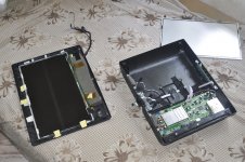
Q: What is a projection panel?

A: A projection panel is much like a normal LCD panel that you see in a laptop with small changes that allow it to be projected. Such as the cables being moved out of the way and fans. This allows it to be put on top of an overhead and projected.

Q: Where can I get these projection panels?

A: The most common and most expensive place is on ebay. Others include normal auctions,universities or offices that are getting rid of them.

Q: How much does a projection panel cost?

A: You can get a decent panel for $100. More features will cost you more money. The best panels generally go for around $300.

Q: What makes one projection panel different from the next?

A: There are several factors involved:

Resolution: This is how many actual pixels are on the panel measured the same way a standard computer monitor is. Higher resolution will yield a better looking image while costing more. Typical resolutions are : 640*480,800*600,1024*768. There are some panels that offer resolutions higher then the "native resolution" this is sometimes called scaling or compression it is not as good as a panel that normally runs at that resolution.

Colors : Colors are the amount of color a panel can display. Generally measured in millions of colors or bits. More colors create a much better looking image. More colors will cost more.

Contrast ratio: This is a big one. This is how much range there is between a pixel on the panel being completely on or completely off. The higher the contrast ratio the better the image especially for white scenes and dark scenes.

Inputs: This is what kind of sources the panel takes. Most panels take VGA input while some have VGA and other connectors such as composite video and S-video. Composite and S-video are used for hooking a DVD player or other video source directly to the panel without the need for a computer.

For reviews on panels check the good panel / bad panel thread here


Q: Can I use a laptop panel??

A: Unfortunately laptops use proprietary connectors and pin outs. You are not
going to find a pinout and hook it up directly to your desktop computer. Driver boards for these panels that allow connection for a regular computer range up into several hundred dollars.

Q: What about a desktop panel?

A: Most desktop panels are 14" unfortunately most projector beds are not this big. Desktop panels also have special ribbon cables which are very very fragile and some are not long enough to allow the panel to be used for projection. The only panel that we know of that allows is the viewsonic vg150 but even then several people have had serious problems with this panel's cable breaking from being flexed one too many times.


Overhead projectors

Q:What is an overhead projector?

A: Commonly seen in schools an overhead projector is a projector that takes a transparency and projects it onto a screen. The LCD is semi transparent which allows it to be projected.

Q: Where can you buy overhead projectors?

A: You can buy overhead projectors from thrift stores,garage sales,office stores (expensive) and ebay.

Q: What is the difference between models of overheads?

A:


Projection type: There are two different types of overhead projectors transmissive and reflective. Reflective type overheads will not work for LCD projection.

Lumens : Lumens is probably the biggest factor in buying an overhead 4 thousand lumens is generally considered the minimum lumens for a overhead more lumens means a brighter image and having more ambient light allowed.

Bulb : Most cheaper overhead projectors use halogen bulbs these are somewhat bright but do not produce the lumens or color tempature that metal halides do. Plus halogens run very hot. Premium overhead projectors use metal halide bulbs these bulbs run cooler,produce better color tempature, more lumens and last longer then halogens. But they also cost more per bulb and require a ballast to run. Some metal halide projectors produce as much as 10,000 lumens!

India again -HD LCD projector .

let the pics speak first.

this happens to be my third attempt and worth to share.🙂

this time with 13.3inch ,1280x850p ( hd) lcd .

work in progress.....🙂

Attachments

  • _DSC0615.jpg
    _DSC0615.jpg
    389.5 KB · Views: 780
  • _DSC0613.jpg
    _DSC0613.jpg
    362.1 KB · Views: 692
  • _DSC0612.jpg
    _DSC0612.jpg
    347.6 KB · Views: 658
  • _DSC0611.jpg
    _DSC0611.jpg
    366.7 KB · Views: 673
  • _DSC0609.jpg
    _DSC0609.jpg
    331.8 KB · Views: 649
  • _DSC0607.jpg
    _DSC0607.jpg
    415.7 KB · Views: 436

Phono Preamp to replace Bottlehead Seduction.

A while ago I purchased a Soundsmith Zephyr MK III cartridge used on Ebay instead of sending my Denon 103R to Soundsmith for an upgrade. What I didn't realize was that the Seduction preamp does not have enough gain for the Zephyr which is a Moving Iron cartridge and requires 38 - 44 dB of gain.
I do love the sound of the cartridge and am looking to keep it in my system.
I purchased a Schiit Mani as a temporary - possibly permanent solution, but after listening to it the first day I think I may need to go back to a tube preamp. I am willing to build one from a kit as I did that with the foreplay. The new phono preamp from Bottlehead the Eros starts at $750. I was hoping to get the kind of performance I want for less than that but if it is the best option I might be willing to spend the money.
I am looking for some guidance and suggestions from the community before I make a decision.
Any help would be greatly appreciated.

Mark Levinson 383 schematics?

Hi,


I am trying to fix my ML383 because it is making a loud pop when you turn it on and sometimes (getting progressivly worse) it makes noise from the right channel.
It sounds like a noisy transistor but the weird thing is the noise is independent of volume or input.
I have been searching the web for 2 days and I'm unable to find any schematics for the amp.

I have opened it up and took out the VG boards and they are quite complex, so
very hard to figure out without a schematic.
Also I found that the left and right boards are basically the same but are a different layout, which I find a bit strange. I would think the left and right channels would be exactly the same but okay because of the construction of the digital control they had to mirror the boards and in doing so they had move things around and also screwwed up on one side because 2 transistors that need to be thermally together they forgot to put next to eachother and botched them on the underside of the board:bigeyes:


I also found that the PCB on the front the selector knob is on a seperate PCB which they did not break from the main PCB and because of that is now deformed. Is that normal? does anybody else have that?


So if anybody can help me with schematics or any other input that would be greatly appreciated.


Thank you.

Lansing heritage forum

I have searched but didn't find anything.

Its been like 4 attempts now to try and register with audioheritage forum. i always get an email that my registration does NOT fulfill some condition...I didn't find anything in the registration form that states some conditions.
Whats up with this group of people?
Anybody knows what is that secret condition? Donating $1000 to the admin?

Honestly, Im not even that keen anymore to be a part of such group. Its just bugging me.

Danny

Stereo Amp/Speaker kit into one pair of speakers

I'm a beginner so please be kind and straightforward.
Building a Bluetooth Speaker from a kit but only using one Woofer and Tweeter.
The kit is a C-Note bookshelf speaker (stereo) and the Amp is a Dayton Audio KAB250v3. So the amp has 2 sets of speaker leads, but I will only be using one tweeter and woofer. I have built the crossovers, but want to know how to wire the speaker from the Amp without causing any amp damage. Should I just pair the -ves together and do the same with the +ves or do I need to build a stereo/mono converter? thanks! Tom

rosin for slipping idler (maybe belts, too)

I had a lumpy idler on my Garrard Lab 80 so I threw on a different one that I had trued and cleaned with CaiKleen RBR. The thing slipped so much it almost would not drive the platter at all: slow start up and slow final speed. Tried cleaning and recleaning and minor roughing with 320 emery cloth - negligible difference. I took some solid rock rosin and smashed it between two aluminum plates until it was as fine as talcum powder, rolled the idler's edge in the powder and brushed off the excess. The result was instant startup to perfect speed, and great resistance to slowing from finger drag on platter edge. Dramatic, instant and complete cure. No idea about whether this might help belt drives, too, or about long term issues, but for now, it's incredible. YMMV

Center project

Greetings,
I am embarking on a center LS project.
I have not found a great deal in the diy sector on the subject so I'm hoping to get some pointer in the right direction here.
This will (eventually )integrate into a 5/6.1 system.
Should it match acoustically with all speakers; my preference leans toword this.
Or is there focus on reproducing vocals?
Generally there are two woofers and one tweeter, are two woofers(in parallel)nessesary? I could guess this helps directionality.
I would like the cabinet to be very long, as to blend in with other aesthetics. Small speakers seem to me to be obtrusive and don't fit in anywhere.

Thoughts and suggestion?
Thanks

Mono Class D Guitar Power Amp

Hi all,

My next project (as an amateur "premade module connector") is a guitar power amplifer designed to take a signal from a preamp or a chain of pedals etc.

These are becoming ever more popular as more and more people are using modelling preamps etc to get their sound, and then just need a compact no frills power amp to power the speakers.

So, my idea is to connect one of these:

DC 24V Universal Regulated Switching Power Supply LED Strip for Printer CCTV | eBay

... to one of these:

60W TPA3118 Digital Amplifier Board AMP DC 10&24V Module PBTL Mono VVP ul | eBay

... and also use one of these:

Male Power Socket Fused Rocker Switch IEC320 C14 Inlet Useful #NP | eBay

Can anyone see any potential issues so far?

If not, my only question is how to add a passive volume control to the input of the amplifier (or to adjust the gain of the circuit?), so that there's some adjustment if the devices connected before it are too loud, and to give a "soft start" on powerup to avoid any unwanted bangs. I'll be mounting it all in an aluminium stomp box type enclosure.

I welcome your comments!

Cheers,

Jim

Tannoy D500 Series 2 refoaming problem

I own a pair of Tannoy D500 Series 2 for nearly 20 years now. Still sound great, lately collaborating with a newly revised Quad 303.

Now my Tannoys need a refoaming, see pics. First action: have a look inside to learn what's inside, and what to order. My problem: I can't get the speakers off the front panel. All four screws were removed easily, but both concentric and bass unit won't move a bit.

Accessing it from the bottom plate or the crossover panel failed, because the damping material (foam) cannot be removed from there.

Any ideas how to proceed?

Attachments

  • DSC05808_sm.jpg
    DSC05808_sm.jpg
    794.7 KB · Views: 251
  • DSC05805_sm.jpg
    DSC05805_sm.jpg
    869.4 KB · Views: 253

When building a ported box does the f3 need to match the fb?

Hello Everyone. I hope everyone is doing well? I had a engineer person I know tell me that the F3 has to match the FB in the design program. I am using the Tang Band 3W-2141 and its cut off is 75hz. I have it at - 2.48 DB at 75 hz. Does this sound right? A lot of speaker company's do minis or plus 3 DB. I thought you would want the curve as flat and even as possible? So here's a example. The Dynaudio Confidence 20 is 155hz at 6 ohms and goes down to 42hz and up to 22khz at + 3 DB. So where is that plus or minis 3 DB in the frequency response?
Am guessing the curved line is not as flat as mine but, maybe am to anal about this box building? Can you please help me out here. Thanks Jeff

TPA3116D2 - Protection

I want to shake my walls. Want louder sound with more BASS.My speakers are 4 ohms

1.Can this little 2.1 subwoofer board can do this?
2.What is the correct power supply to use?
3.Do I need a speaker protection ? Will it burn my expensive speakers when output stage falls?

Going to buy this..!!
WAVGAT New Amplifier Board TPA3116D2 50Wx2+100W 2.1 Channel Digital Subwoofer Power 12~24V|Amplifier| - AliExpress

suggeted kit for simple power amp build?- has to power electrostatic speakers

I'm having my first go at building an amplifier I'd like to build a power amplifier-I take it thats easier if anything than an integrated amp? Its to power a pair of older Acoustat electrostrostatic speakers that suck power like nothing else😀 so I was looking for recomendations for a simple kit or plan of a kit where I can buy the bits that has enough power to power the electrostatics

I Need to Network

Hello,

My question is: What is the best method to add networking capabilities to my non-networking DAC?

Current setup:

Internet -> Workstation USB port -> USB Cable -> USB Port of SMSL SU-8 DAC -> Receiver

I would like to eliminate the USB cable piece of the above setup and replace it with some sort of wireless solution. My first thought was that possibly some wireless USB solution exists. Does anyone have experience with such and what specific device would you recommend?

Is there a better method of adding networking capabilities than wireless USB? the unit also has optical and coaxial ports. If so, what would you recommend?

I am moving my office to another room and the new setup does not allow to run a USB cable from computer to where the DAC would be located. I also use my workstation as a CD player.

Thanks in advance.

Best

Alien

Lab12c + 4" Precision Port - optimum cabinet volume?

My goal is to hit 105 dB @ 30 Hz/1m, before reaching Xmax. This will be for a 3 way studio monitor, crossed over @ ~200 Hz to a Beyma 8CX300Fe coaxial. I will use the Eminence Lab12c as it is (luckily) available here in India at a price that makes sense. I want to use a 4" Precision port kit because of it's off the shelf availability. I would like to limit box width and depth to 19" and 17" respectively, height can be anything up to 36". Response below 30 Hz can be compromised. It will be driven by a Hypex FA253 if 250W is enough to accomplish what I have in mind. If not I will opt for the 500W version.

With these things in mind and my half baked knowledge of the stuff, I have been chasing my tail with WinISD and other tools... flummoxed with finding a solution with optimum Qtc, port length, port resonance, group delay etc., and I realize that there is too much I do not know...

I'm hoping it is a simple thing for you experienced people to chime in with an optimum cabinet volume and port length and equalization settings (the Hypex has 15 "biquads" available), given the above design goals.

Please be kind and let this noob climb on to your collective massive shoulders.

bhFkY7oH1Dw3y9ZU1rEogBzBYSyzlM-taWxbjgOxBBWtYG8_EBwusvnsD5P6dvahLedEg6ev61H0IqeoC5d9_B5TTDMVGRdXIRTJV9ymPENgZGnyJWOE5ej1kC9OuJt0qbhaByVCwA=w2400

I fixed buzz in Sonigistix Monsoon planar magnetic drivers

I just discovered this manufacturing problem in the main panels: There is a plating on the bar magnets which partially peels loose and causes a buzz.
A couple of days ago, I persuaded a friend to sell me his MM-1000, and while dusting and running a 200-300Hz tone through them heard an annoying buzz from both. (I had heard the buzz earlier while playing music: Israel Kamakawiwo'ole's 'It's a Beautiful World' is perfect for exciting this buzz.) Wondering if it was a track that had come loose from the diaphragm or something, I began poking through the rear slots (with the rounded end of a small plastic tie wrap so that I didn't damage the diaphragm) and discovered that the magnets have a plating which had begun to peel and separate from the magnets, and this partially loose piece of plating was now vibrating in the gap. Each unit oddly had only one area which was separating, and it was actually visible through the slots in the rear once I realized what I was looking at. (You can't see anything from the front as there's a sheet of black felt between the diaphragm and stators.) With a lot of patience and some bent wire ties of different sizes (I bent the end of the wire ties into an L, so that I could actually scrape the far side of the magnet facing the diaphragm.) and a pair of tweezers I was able to push, scrape, drag, and pull out the offending pieces of plating, and now the speakers sound good again.

Earphone Cable Question

I am using Canare L-2B2AT wire, it has one +, one -, and one ground. 3.2mm total diameter. My dad's kind enough to solder it together for me, but he asked a question I don't know how to answer.

For a 3.5mm MMCX cable, for this Canare wire, do I have to double up the wire for it to work? Meaning, for example, 2x1.3m?

Help would be appreciated.

Thanks alot,
Kasper

Parallel vs Series

I have two pairs of woofers that are dual voice coils. Each voice coil is 4 Ohms. I want to install them dual-woofer floor-standing speakers and need 4 Ohms per cabinet. So, what should I wire between?

A) series wiring dual voice coils together to make each driver 8 Ohms, then, parallel two drivers to make the system 4 Ohms.
B) parallel wiring dual voice coils together to make each driver 2 Ohms, then, series two drivers to make the system 4 Ohms.

Thank you

Elekit tube set options

ELROG 300B + Telefunken ECC83X 1 + ECC82 X 2 $1,950
ELROG 300B + Telefunken ECC83X 1 + Seimens ECC82 X2 $1,650
ACME 300B + Telefunken ECC83 X 1 + Seimens ECC82 X2 $1,200
ACME 300B + WE5755 + RCA 12AU7 X 2 (clear Top) $875
Psavne WE300B + Telefunken ECC83 X 1 + Seimens ECC82 X2 $975
Psavne WE300B + WE5755 + RCA 12AU7 X 2 (clear Top) $750
LINLAI/COSSOR Black Plate 300B (MADE BY LINLAI)+ WE5755 + RCA 12AU7 X 2 (clear Top) $285.
LINLAI WE300B (MADE BY LINLAI) WE5755 + RCA 12AU7 X 2 (clear Top) $625

ACME 300B, PSAVNE WE300 & NS WE300B

Individual Tube
300B Tube per pair
ELROG 300B/$1,475.00
ACME 300B/$ 875.00
Psvane WE300B/$775.00
COSSOR Black Plate 300B/$195 (MADE BY LINLAI))
COSSOR WE300B/$495 (MADE BY LINLAI)
WE5755 with Adapter $45 (with getter)
WE5775 + RCA Clear TOP
RCA clear top 12AU7 $45
Gold Lion (B749 X 2 + B759 X 1) $100
EH Gold ECC83 X 1 + ECC82X 2 $60

Coupling Caps
Mundorf EVO Supreme Silver Gold 0.1 X 4 $150
V-Cap ODAM (Oil Damped Advanced Metalized) 0.1 X 4 $200
V-Cap CuTF Copper Foil and Fluoropolymer Film 0.1 x 4 $380

Carbon Resistor
Takman 2% $65

Volume Pot
TKD 2CP601S with conversion Kit $65

Lundahl LL2785 fix

I received my new 8600SVK. Upon opening one of the LL2785s, I noted that a number of the solder pins had been bent. In partucular, a solder pin on the primary had been flattened against the board. Despite carefully trying to straighten the pin, it of course seperated at the board level. 🙁

There looks to be just enough remaining copper lead to pull through to establish a new joint. It also appears the lead is held in place by resin? Presumedly, i would have to apply some heat and carefully push / pull through the remaining copper lead and then build up a layer of solder? I also presume that soldering will melt the insulation?

Has anyone tried this repair with success? (solder temps etc.)

Attachments

  • LL2785_1.jpg
    LL2785_1.jpg
    381.7 KB · Views: 190

Questions About This Local NFB Scheme

I'd like to hear some comments on the local NFB scheme in this schematic I found.

I'm also wondering about its use of a 1N4007 in both the B+ and G2 supply. What is their purpose? Would there be a problem if they are omitted?

I have a SE VM that originally had the preamp section connected with an umbilical. The amp section only has a 5Y3 and a pair of 6BQ5s. I want to drive it with either a stand-alone tube pre I built or a SS pre. So I won't be using global NFB like the one that went to the stock preamp through the umbilical.

My amp does NOT have an UL tap like the one in the schematic. I want to get as much power out of it as I can so I want to stick with pentode instead of converting it to triode.

So it's either pentode with no FB or some type of local FB. Are there other local FB methods that I should consider?

Attachments

  • Local NFB Scheme.png
    Local NFB Scheme.png
    20.9 KB · Views: 524

Amp Camp 1.6 Boards w/ TungstenAudio Mods & Cap Multiplier Boards

I am about to move and will not be able to complete my Amp Camp Build that includes Tungstenaudio's modifications and stuffed Cap Multiplier boards.

The ACA Boards include Nichicon Super Through Caps (C2), Organic Polymers (C4), and Nichicon Gold Tune Filter Caps (C1). I used mostly Vishay/Dale resistors and MPC71 Futaba resistors for R1/R2. I made the resistor changes to R3, R4, R11, and R12 according to the new schematic and added a 10pf silver Mica across R12. Mosfets are IRFP140s and rubber pads used for heat dissipation. Both boards were tested and biased perfectly to 12V.

The Power supplies were designed by Rudi Rozek based on Jason Kuetemann's Cap Multiplier. I have used this design on all of my amp camps with an Antek AS-2222 Torroidal Transformer and way prefer it over the Meanwell Power Block.

The heatsinks were cut from a 8Hx9Dx3W heatsinks. I cut them in have to measure 4Hx9Dx3W(fins). The heatsinks had some pre-drilled holes but they are not noticeable.

To finish the amp, build a nice chassis, add the rca/speaker posts, and buy the transformer.

For all 4 boards and the heatsinks I am asking $165 SHIPPED in the CONUS only please.

Attachments

  • IMG_1303.jpg
    IMG_1303.jpg
    889.6 KB · Views: 298
  • IMG_1302.jpg
    IMG_1302.jpg
    844 KB · Views: 292
  • IMG_1301.jpg
    IMG_1301.jpg
    775 KB · Views: 284
  • IMG_1300.jpg
    IMG_1300.jpg
    869.9 KB · Views: 296
  • IMG_1299.jpg
    IMG_1299.jpg
    441.1 KB · Views: 265

3 pins capacitor

Hello.
I would like to have some help with those capacitor in the pictures (negative side on the right).
Anybody knows what if the third pin is just for stability or is this a shield?
Also how can I test them. They are probably 20 years old and I would like to be certain I will not blow anything if I use them.
Thank you very much.

Attachments

  • WP_20200806_20_10_14_Pro.jpg
    WP_20200806_20_10_14_Pro.jpg
    935.7 KB · Views: 271
  • WP_20200806_20_10_40_Pro.jpg
    WP_20200806_20_10_40_Pro.jpg
    888.6 KB · Views: 251

unknown power transformer

Can someone help me to identify this tube amp power transformer?
There are no markings whatsoever but I have verified that it is good. The lead insulation is braided cloth. I'd like to try and get the ampere ratings for the windings.

The core size is EI-96 80mm x 96mm (3-1/8" x 3-3/4")
The core thickness is 41mm (1-5/8")
Weight: 5 lbs., 5 oz.

The primary measures 3.5 ohms
The HV secondary measures 168 ohms total

Here is what I measured:
BLK - 120V input
BLK - 120V input

RED - 380V
WHT/RED - CT
RED - 380V

GRN - 3.2V
WHT/GRN - CT
GRN - 3.2V

WHT - 5V
WHT - 5V

Thanks.

Attachments

  • IMG_20200812_092424.jpg
    IMG_20200812_092424.jpg
    286.4 KB · Views: 143
  • IMG_20200812_092509.jpg
    IMG_20200812_092509.jpg
    280.1 KB · Views: 152

USB noise issue has gotten more bizarre

I thought I had fixed my noisy USB port issues when I added the iFi iDefender+ (powered from a separate USB charger) between my computer & my DAC. However a new noise has recently started coming through my speakers, this time a continuous high pitch (maybe ~1KHz?) rather than the previous noise that was related to mouse movement/screen activity. After a lot of frustrating troubleshooting I have discovered where I think the problem lies & could do with a fresh set of eyes trying to come up with a solution!

My DAC has RCA outputs on the back, which are connected to my amplifier for my speakers. The DAC also has a 1/4" TRS headphone output on the front. Both outputs are volume controlled via the knob on the front.

I noticed that the new high pitched noise was only playing through my speakers, not my headphones. So as an experiment, I connected both the RCA output & the heaphone output of the DAC to a small passive mixer (eg no power supply connected), so that I could easily listen to each output in turn through the speakers. This is the first picture; on the mixer, output is going to my amplifier, ch 3 input is coming from the DAC's RCA output on its rear, ch2 input is coming from the DAC's headphone output on its front. To my surprise, there was absolutely no trace of the high pitched noise in the speakers when listening to either input.

After some more experimenting, I discovered that the high pitched noise in the RCA output disappeared as long as the ground of the headphone output was connected to the ground of the mixer. When I disconnected the headphone output, as in the second picture, the high pitch noise came back through the speakers.

I did some more experiments. Just touching the ground of the headphone output to the ground of an input on the mixer was sufficient to remove the high pitch noise (third picture), likewise when just touching the ground of the headphone output to the RCA connector going to the amplifier (fourth picture).

However, when I removed the mixer, connected the DAC's RCA output directly to the amplifier & then touched the ground of the headphone output to the RCA output (fifth & sixth pictures) this did not remove the high pitch noise.

So, what exactly is happening when joining the grounds in the mixer (remembering that this is a passive mixer with no power supply), which isn't happening when joining the grounds at the DAC? With no cables connected there is continuity between all ground connections on the mixer. I even opened up the mixer (final two photos) looking for hints, but couldn't make heads or tails of it.

Essentially, why is the result of the fourth photo different to the result of the fifth/sixth photos?

Any ideas, please enlighten me - it's late & I'm thoroughly confused!

Attachments

  • IMG_20200809_221457.jpg
    IMG_20200809_221457.jpg
    289 KB · Views: 206
  • IMG_20200809_221515.jpg
    IMG_20200809_221515.jpg
    259.7 KB · Views: 211
  • IMG_20200809_221535.jpg
    IMG_20200809_221535.jpg
    254.6 KB · Views: 206
  • IMG_20200809_221603.jpg
    IMG_20200809_221603.jpg
    253.8 KB · Views: 201
  • IMG_20200809_221723.jpg
    IMG_20200809_221723.jpg
    145 KB · Views: 209
  • IMG_20200809_221751.jpg
    IMG_20200809_221751.jpg
    305.4 KB · Views: 91
  • DSC04789.jpg
    DSC04789.jpg
    591.2 KB · Views: 104
  • DSC04790.jpg
    DSC04790.jpg
    440.1 KB · Views: 105

NAD 3240 short

Firstly thank you to the folks on here who have introduced me to the dim bulb tester. If only I'd found this earlier I would have saved my self from quite a few pyrotechnic episodes!

So to the point of this post, my faulty 3240. Being a newbie to electronics I'm on a steep learning curve. I purchased this amp with a silent left channel, however, as I intend to keep this one for my own use in my study for a while, I decided to go to town on it, expecting to locate the faulty component(s) along the way.

So, I replaced all the electrolytic caps, testing as I went. All still measured to spec, so this is purely for quality upgrade, not fault fix. The main power caps I up'd to 10,000uF from DNM.

I also removed all of the transistors and tested them using the voltage drop on my diode tester. Again, all measured okay. The power transistors were replaced from a reliable source, not eBay(!) with like for like.

I fitted an external IEC power socket to get rid of the original NAD mains cable in favour of one from Lapp. Finally, I added new speaker binding posts in solid copper with 14 gauge wire running directly from the underside of the board from the speaker connection points for speakers A. This bypasses the horrid originals and the truly nasty four way plug on the speaker post board.

I also hard wired the preamp out to the power amp in, eliminating the need for external links going through RCA sockets on the rear panel.

So to the issue. I connected the amp to the mains using my freshly built dim bulb circuit and switched it on. The lamp came on and stayed on. This seems to me to be indicating a short.

I carried out a quick visual inspection and found a horrific error in my wiring. I had reversed live and neutral on the socket. A complete brain fade on building it. I put it down to being made redundant by C-19!

Anyway, I rewired the socket and went for it a second time, ensuring the DBT was safely in place. Unfortunately it failed to bring the amp back to life and the DBT shines brightly.

I now need to diagnose the issue and I would welcome any suggestions.

Behold the circuit that destroyed my preconception on capacitor induced distortions

It happened 10 years ago when i made a mod to my newly refurbished Realistic STA 2250 .Although the power amp was completely up to date-nichicon muse, ultra low noise and high ft transistors, the eq had way too many electrolitic capacitors in the signal path, actually 11(eleven) 40 years old capacitor , so before changing them i thought of rewiring the tape- monitor switches to be able to bypass the entire tone stack.After doing so and leveling the input output signals, my complete and utter surprise was that i wasn't able to hear anything wrong with the tone eq in.There was somewhat of a different sound, but the differences weren't in favour of removing the tone stack...they were completely irrelevant, like 0.5... 1db out of tune circuit, but nothing to criticise .From that point on to these days i simply disregarded any claim of a better sound due to dc coupling.

Attachments

  • realistic.png
    realistic.png
    631.5 KB · Views: 529

Recommendation for a Newbie

Hello DIYers!

I’d like to start playing with my first DIY Amplifier, I know they’re outdated and there are more efficient packages out there but I love the looks of TO-3 power transistors.

So with that being said I’m wondering if you knew about a design that could work with low voltage high current transistors that I may modify the output stage a bit to make it work, it could be Class A or Class AB either Complementary or Quasi.

I want to use it as a learning experience and if possible, and that’s why I mentioned low voltage high current transistors, I’d like to use the transistors I have 2N5302, and I have a TON!!!, my understanding is that its complementary is the 2N4399.

And please if you think those transistors just won’t work I’d understand but please provide details about why, remember I'm trying to learn 🙂...

Thanks in Advance!

B78685EE-A5FF-4F0E-9A76-AB9A4101FB37.jpg

6SN7's for experimenting

Hi there, I'm just wondering what you might use if you were doing this.

Just got the PT in and gathering parts and components for amp project #3, a monoblock line level single instrument amp, probably use a pair of KT88's UL in the output section - preamp stages, eq etc to be determined by experimenting.

I'd like to kick this off as a hi fi amp and see how the 6SN7 tubes work in the preamp.

My question is, if you were planning on the final amp using NOS tubes, which current production 6SN7's would you use for the initial experimentation/design phase? Reason I ask is that I often see that some current production tubes are not thought of as having similar electrical characteristics as their older counterparts. I'd like to work with modern 6SN7's that will have a similar performance to any or most NOS ones that are substituted. I'm probably worrying over nothing and thats probably true. But where I'm certainly no expert on these tubes I'd be interested in comments from those that do have a long term familiarity with them. Plus, if I do something crazy during the experimental phase, I'd rather take out a 15 dollar JJ than a nice old expensive NOS tube.

Which current production cheaper 6SN7 would you use for design with the possibility of trying much older ones later on?

Thanks very much,

Phil

Flickering glare from coil winding.

Here's a bothering problem I'm searching a solution for. I've been an audio transformer coil winder since three years. I'm putting a lot of light around the winding process to follow the tiniest details and constantly watch over the wire for crossovers, especially with ultra fine ones.

The coils are rectangular and there are surface glares from the magnet wire copper layer directly into the eyes while the coil rotates. This becomes really taxing on the nervous system when one has to wind thousands of carefully placed turns per day.


You can slightly get the idea of the glare, which is visible on the top part of the coil

One thought I will be trying soon are polarized anti glare glasses.
Do you think of any other tips?

This student wants to know how to progress in electronics

There didn't seem to be a more appropriate place to post this, so if it needs to get towed elsewhere, let me apologize in advance. My frustration has been mounting as I take on projects. I don't want to muddy any of my other threads.

I have a hard time learning electronics. I have grown up around it, I have some amazing friends that are very into it, and I've tried very hard to pick it up myself. I have an above average IQ and lots of general knowledge about everything. I just have a hard time specializing. I've really worked my tail off trying to get past my study obstacles. I don't get discouraged but I do get frustrated, and my way of dealing with that is to apply humor. Hopefully people see that.

In the past few months I've been studying and seen some progress. I have the basics covered on passive components. I've learned what a voltage divider is, and how a rectifier bridge works. I can find them on a schematic, and I can also identify input and output sections on schematics if they're well organized. Those are things that I had a hard time with so I know progress is possible. I've reached sort of a plateau now, though. I know what a generic "transistor" does on its own but I can't tell you the difference between all the different types, and I lose my mind when I try to figure out what they do in the circuit. When I start reading about using a transistor to boost current vs transistors to boost voltage, my brain shuts off. I have to decompress for a while, and then go relearn the difference between current and voltage, I kid you not. And if you asked me right now to explain voltage - even though I can use a DMM and diagnose problems with a basic circuit - I have to go review it before I discuss it. You have no idea how many times I've read it over, watched waterwheel metaphor videos explaining it, and passed tests proving that I had the knowledge, only to forget it a few days or weeks later. Its not really an issue - as long as I know how to use the meter, and I can look up those explanations, I can get by. Its no different than having a calculator to do the math for circuits instead of doing it long-hand.

I think the reason why I can't move forward now is I can't get past the whole "voltage goes in here, goes out there" mindset when I study circuits. I'm a linear thinker. Things go from one place, go through some work, and end up on the other side. I know what that rectifier bridge does, and if I sit and map it out I can even explain it. But its still difficult for me to follow because there's four traces, one at each corner instead of one wire going in and one going out. So I had to learn the concept, look at it as a single device, and just pay attention to the values going in and coming out. Thats the only way I don't get stopped there every time I see one on a schematic.

Pick something exceedingly simple, like a GFA-535 (one of the simplest high-performance designs in existence) and can I try to follow it. My brain sees the signal coming in from the input, going past a handful of passives and into a transistor. But right next to it on the schematic is another transistor (making a differential pair), and there's a signal going in to it from somewhere else. Where the heck is that coming from? Its from that spaghetti mess to the right of it on the schematic. I think "why isn't the differential pair turned on its side, with all that stuff from the right now placed to the left, between the input and the pair, so that I can follow it from left to right?" And thats where I stop understanding the circuit. Now all I see are these traces that jump over each other, blend with each other, diverge from each other. Its very hard for me to follow because I keep looking at the circuit as a rollercoaster track for electrons, when I should be looking at it as a web of interconnected things that all affect each other.

But thats just the signal - what about the power that runs the whole thing? Well, thats over on the right side of the schematic. Why isn't it listed on the left side with the signal input so its easier to follow? Or put it above or below on the schematic so I'm not trying to pick the speaker outputs out of the power traces. Having the power come in the diagram on the output side seems like a restaurant kitchen: all the orders come in the same door that they go out, with the deliveries on the other side of the kitchen. Or something like that, I'm still working on the metaphor. In any case, it looks like a mess to me, while to you guys, you can follow right along. I was trying to figure out my Hafler preamp, and Maaco here said to me "start with the basics - follow the circuit". I couldn't, because there wasn't a linear path to follow.

I understand my major issue here - I look at the circuit from left to right, and follow the electron. This is completely wrong, and yet I have no idea how to get past it. Dahl tells me "don't look at it that way, the electrons are always there, they're just not moving until the circuit goes on. You shouldn't be following an electron through the path, you should be looking at what current and what voltage you have in any part of your circuit." Great! I know voltages and currents move and do things, but I still look at it as "moves from here, goes here".

At one point I learned I had been looking at amplifiers the wrong way: I originally thought that the AC was split by the power supply to positive and negative legs of DC, the whole amp was divided into a positive side and a negative side, and then those two sides were combined after the output stage to make an AC signal again. (Oddly, that actually worked in my head.) Then I saw this brilliant little animation that demonstrated how a transistor worked in an audio circuit, how the DC ran one way, but there was an AC signal in there that ran the opposite way, against the DC power that was coming in. That really helped me to understand that the amp was running off DC but the signal was going through there as AC. I had no idea! Then I lost the link to the animation so I have no idea where I should have gone next, and the stuff I learned is slowly disappearing out of my brain.

While I'm talking about it - I still don't understand AC, believe it or not. Since I'm a linear person, DC is easy: Its either there or it isn't, and it moves thataway. Put a negative sign there, and its moving the opposite direction. But AC changes back and forth, so how do you get anything done if things are going back and forth? Using the stupid waterwheel analogy, if the water flows in one direction the wheel turns, there's your current - but what if the water runs backwards? Will that waterwheel run backwards and turn flour into grain then? This isn't even touching on the whole "its not really just negative and positive, you actually have 360 degrees of phase, not 180".

I'll leave that for my doctoral thesis, I think.

And don't get me started about the little directional arrows that distinguish PNP from NPN. To my tired little brain that says "goes in here/goes out here", I can't get myself to see it any differently, and of course it doesn't mean that.

I've been studying this, on and off, for at least 6 months. Its not sinking in. How do I get past this? How did you guys get past it? You all had to start somewhere and go through the steps, so how about letting me in on your "aha!" moments.

TIA.

FS: Jensen CI-2RR IsoMax Stereo Audio Isolator

Jensen CI-2RR IsoMax Stereo Audio Isolator. Great tool to have in your toolbox.

I have had this for probably 12 years now. I have never installed it in a system. I even forgot about it until today when I was cleaning out my garage.

I am asking $160 shipped, CONUS. Online prices are $190+.

Pictures attached.

PM me if you're interested.

Attachments

  • jensen1.png
    jensen1.png
    187.5 KB · Views: 153
  • jensen2.png
    jensen2.png
    273.5 KB · Views: 155
  • jensen3.png
    jensen3.png
    233.8 KB · Views: 155

Peerless 12" Double box

Hello diyers

Currently working on this double peerless xls 12 850000 driver loaded double slot ported cab with single chamber:

IMG-20200812-144336-01-2 — ImgBB

As of now its tuned to 25 hz, but id love your input on what kind of performance i can expect here, if i should brace it alot more etc. Its made from 19mm MDF, glued and screwed ☺️

Thanks alot in advance - also, is the crown xls 1002 a good contender for power? With its inbuilt bandpass filtering etc.

All input is highly appreciated!
Thank you.
Projects by fanatics, for fanatics
Get answers and advice for everyone wanting to learn the art of audio.
Join the Community
507,807
Members
7,889,186
Messages

Filter

Forum Statistics

Threads
406,280
Messages
7,889,186
Members
507,807
Latest member
Mark1979!