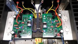
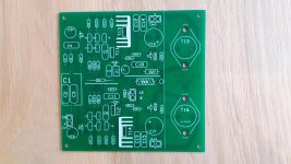
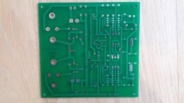
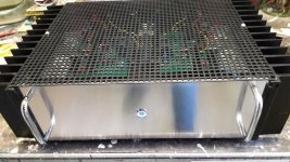
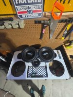
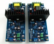
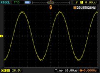
Need help with this audio amplifier. If this circuit can work?

Hi,
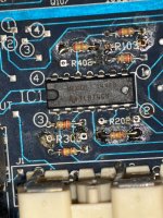
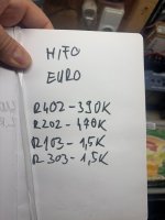
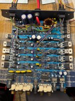
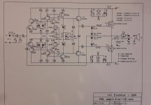
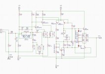
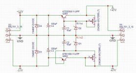
Is there a way someone can take a look at the attached schematic and advise if this will work. Circuit is just the amplification section from a high current Denon amp. I have listed to this amp and the output is just chest pounding. Procuring the output Darlington transistors pair in India is a nightmare,The TIP 142/147 is easily available with less power. Any recommendation/suggestion to modify the circuit to replace the output transistors is a welcome

Attachments

  • Circuit.jpg
    Circuit.jpg
    177 KB · Views: 464
  • 15v linear symmetric supply.jpg
    15v linear symmetric supply.jpg
    80.1 KB · Views: 452

Reworked Mission Model 70 Mk2 speaker

I had a pair of these on the shelf for about 10 years with a crossover and Vifa D19 tweeters that were cannibalised somewhere along the line.

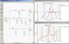
Wanting to re-instate and use up the spare parts bin, I re-measured and designed a new crossover. I ended up being a little aggressive on BSC according to the measurements, but it actually sounds balanced to my ear in my room (so far), so will leave as is. This could be an artefact of the final measure I did which wasn't in the same environment as the raw driver measurements. Crossover uses unsmoothed but gated responses, with quasi-nearfield woofer (nearfield + BSC merged with gated farfield). Final measure (green/red each speaker) is full in room sweep with 1/3rd octave smoothing.

The last curve is RED/GREEN = measured left/right speakers in room and ORANGE = simulation (based on individual driver measurements). Z offset (not in picture - set on driver tab) 36mm on woofer.
1706137590488.png
1706137598434.png
1706137650685.png
1706137664795.png

1706137681329.png
1706137697904.png

SigmaDSPstudio 3.15 download?

I've got a small problem. I need to update my Sigmastudio install to v3.15 to be able to use one of the newer DSPs, but when I go to analog.com I find there's no 32bit versions available anymore 🙁. This is a pain as a) I don't have spare funds to buy a new PC (can't update this one due to custom apps) and b) I hear rumours of backwards non-compatibility between 64 and 32 bit versions which would stop me re-using/rehashing some of my old designs which would save a heap of time.... I've raised it with AD on their "engineer zone" , but had nothing back: looking at the list of unanswered posts it looks like no-one from AD has answered anything on there for at least a week, so I'm not holding my breath 😡 Does anyone have or know where I can find a download please?
  • Like
Reactions: stewin

Multiplied Transconductance Amplifier based MM Phono-Preamplifier

Here's my take on the Multiplied Transconductance Amplifier (MTA)-concept presented by Frank Blöhbaum in Linear Audio Vol. 6 & 8.
In contrast to the circuits present by the author in his excellent article, I run this preamp without global feedback.
By doing so I could avoid the input resistor, which limits the use of this circuit as a phono preamplifier because of the additional noise it generates (it is in series with the source). Of cause this comes with the penalty of higher distortion figuers.

I had some of this pencile tubes 6N16B lying around for a long time and without any use, so I deceided to use them for it. I designed a single-sided board which I etched by myself. For all other parts I only used what I already had at hand: PP-caps for in- and output coupling; PPS caps for the RIAA network; generic metalfilm resistors; a 6Z4 rectifier tube and vintage VB408 voltage regulators (more on this later) -no fancy parts here.

This is roughly the circuit suggested by Frank Blöhbaum; bias-current is set by R9 and by R4 for V1b.
T1 serves as a "transconductance-multiplier" for V1a whereas R5 transforms the collector-current to a voltage for the next triode V1b.
Screenshot 2025-01-20 114521.jpg


...next I changed R5 to an RIAA network:
Screenshot 2024-12-24 125849.jpg


...and that was actually it. The real circuit has of course some more parts, mainly for saftey- and protection.
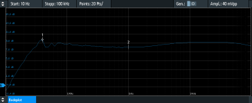
The first tests were promissing: wide bandwith (20Hz to >>100kHz) and high gain (49dB). Input resistance is ~45kOhm.

Frequency-response (the 40mV input is scaled down by the anti-RIAA by 100):
MTA-ph_fgang04a.PNG


Since I only used parts I already had, in this case a 230:230V transformer, I had to get rid of some excess voltage in the PSU -and what does this more elegant than a tube rectifier?
The CCS is realised with a LM317 in a TO-92 housing; a resistor instead of the CCS will do the job as well- but I had a lot of these Vregs left.
I expected this amplifier not to have good PSSR, so I put two VB408 voltage regulators, one for each channel, behind the rectifier.
Heater voltages are supplied by a separate transformer, rectified and filtered.

The first test-board with PSU:
mta-ph-001.jpg


The final amplifier in a housing. The corner-elements are 3D-printed, the alu sheets are from the bin.
Protection earth and signal ground are separated by an ICL (10Ohm @ 20°C). Some rubber pads serve as provisorical feet.
I also forgot a separate grounding-connector for the tonearm, so I clamped the grounding connector from the tonearm wire under the top cover sheet (in contrast to my other phono-preamps it made a difference here when I connected it- possibly a result of the input-capacitor? My other phono-pres are DC-coupled in to out).

IMG_20241216_115649.jpg


I was surprised by the low noise (there's no hum) and the vivid and natural sound with deep and articulate bass.
In the last years I have bulid more than 10 phono-amplifiers (with Opamps and transistors), most of them better than it's particular predecessor; the last 5 or so with LR equalization, which I found superior so far. This amplifier is something special. My latest LR-phono is a tad more detailed and neutral, but this one lives...

This was my first attempt with this topology and I found it very promising. I'm already in the process of builing the next version with noval-tubes and some other modifications.
Cheers, Boris

Attachments

  • MTA-ph_fgang04a.PNG
    MTA-ph_fgang04a.PNG
    19.6 KB · Views: 43

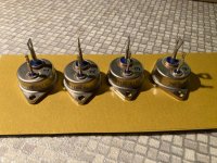
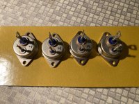
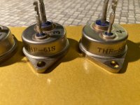
For Sale 2 matched pairs Tokin THF-51S SITs

Hey guys, here for sale is a quad of NOS THF – 51S from watanabe in Tokyo.

I bought these couple years ago for a Papa project, but I have gone a different direction and probably will not use these, it’s a shame to just let them sit….

I recall they are 2 matched pairs, but I don’t have the paperwork anymore.

The pairs are #1 and #2, and then #3 and #4 from what I remember, but, as I said, it’s a while ago, so I can’t be sure.

€380 plus shipping, for the quad.
Paypal friends and family

These will ship from Austria, near Vienna.

Thanks

Attachments

  • IMG_1799.jpeg
    IMG_1799.jpeg
    951.2 KB · Views: 65
  • IMG_1800.jpeg
    IMG_1800.jpeg
    1.1 MB · Views: 63
  • IMG_1801.jpeg
    IMG_1801.jpeg
    665.5 KB · Views: 66
  • IMG_1802.jpeg
    IMG_1802.jpeg
    728.1 KB · Views: 64

Elektor AXL V2 with Lateral MOSFETs

More then 30 years ago (1985) I build the Elektor AXL class A/AB amplifier, time to upgrade this amplifier using new (= better)components.
My main goal was to replace the power mosfets 2SK134/2SJ49 with Exicon ECF10N20/ECF10P20. Also the medium power transistor BF469/BF470 changed to MJE340G/MJE350G.
Extra power supply filter capacitors where used and placed on the PCB.
The two capacitors for the 15V zener diodes where increased to 100uF 25V
and the capacitor parallel to the quiescent current potentiometer (1k) is increased to 220 µF (Single-Ended Conductive Polymer Aluminum Solid Electrolytic Capacitors)plus extra 47nF WIMA MKP.
The two source resistors (0,22 Ohm) are no longer needed.
The input capacitor (C1,C2,C3-820 nF) is replaced by a high end capacitor 2,7 uF Clarity Cap ESA.
The Exicon Application notes told me to decrease the inductance in the output line to 1µH (1mm Cu wire inner diameter 8 mm, 15 windings). Due to different gate input capacitance of the mosfets the gate resistors are also different, 330 Ohm for ECF10N20 and 220 Ohm for ECF10P20.
The power supply for each channel (2x25V AC 2,4A 120 VA) is filtered by 4 x 10.000 µF rectifier (Ebay) so that results in 2 x 38V DC output voltage.
It is still very important to set the quiescent current potentiometer to zero Ohm before switching on the amplifier for the first time.
I tried to use the same component labels but did not 100 percent succeed.
On my old (same as me) but still working oscilloscope (Philips PM3226) I saw a maximum error free waveform of about 60 Volt peak-peak with a 8 Ohm resistor load.
No oscillation what so ever, 60 Volt peak to peak over 8 Ohm i.e. 30 : 1,4 = 22 Watt output power with a quiescent current 0,1 A.
The calculated damping factor is more then 200.
I am using a Rasberry Pi in combination with the HiFiBerry DAC plus and a home made power supply (5V 3A), controlled by Volumio software, NAS. The loudspeakers: Acoustic Energy AE1.

Attachments

  • AXL-v2-schema.jpg
    AXL-v2-schema.jpg
    303.4 KB · Views: 2,548
  • AXL-v2-assambled.jpg
    AXL-v2-assambled.jpg
    701 KB · Views: 2,323
  • AXL-v2-PCB-scl.jpg
    AXL-v2-PCB-scl.jpg
    588.1 KB · Views: 1,932
  • AXL-v2-PCB-bcl.jpg
    AXL-v2-PCB-bcl.jpg
    536.3 KB · Views: 1,670
  • AXL-v2.jpg
    AXL-v2.jpg
    707.9 KB · Views: 1,928

For Sale Adire Brahma Mk2 15" Monster Subwoofer

Hello all,

I have an incredible Adire Brahma 15" 8-ohm subwoofer driver for sale
It's seen minimal use and is in very good condition
Cast frame, heavy duty rubber surround, huge ferrite magnet, 2x 2-ohm voice coils that can be series or parallel connected
XBL2 technology with x-max = +/- 29mm!
This is a monster driver so probably only suitable for shipping within Australia?
I'm thinking USD 300 is a fair price but open to offers

Cheers, Ralph

Adire Brahma1a.jpg

Adire Brahma2a.jpg


https://audiofile.net.au/

Attachments

Carver M1.0t - wish I hadn't bought it.

So I have a story. Many years ago I had a Kenwood KA3500 integrated amp and enjoyed it for about 10 years. For some reason I decided I needed more power and read a Stereophile Article that favorably compared a Carver amp against a very expensive tube amp. After reading the article I decided to buy the amp on Sterophile's review and it was also on their list of recommended components. I hooked it up and listened and was sort of disappointed. Especially with the bass (a little flabby). Then I decided that because I was using the preamp output from the Kenwood, I needed a dedicated preamp. SO I bought a Rotel preamp. I don't remember hearing much difference. I know this isn't exactly DIY, but I am just curious if anyone else has had a similar experience. It was a rather expensive lesson. (buying something based on a review in a magazine).

Better replacement for LM317/LM337

Hi, we all know that the LM317/LM337 are certainly not bad, at least better than 78XX and 79XX.

I have the those three legged regulators in my DAC (set to 15V), with quite little space around. Audiophonics have this: https://www.audiophonics.fr/en/voltage-regulator/lt3045-linear-voltage-regulator-15v-p-17097.html, but the connecting is not compatible as they are more for a 7815 direct replacement.

Is there anything similar with the LM pinout, maybe to be set with the existing trimmer, or a fixed output and I remove the trimmer?

Thanks
- dan

Dual PSU build in Mini Dissipante 3U/400mm for F5m/F4/M2x/Aleph Jzm

Just pulled the trigger on a Mini Dissipante 3U * 400mm chassis, with custom cutouts for the front and rear panels, and pre-drilled heatsink holes for some of the amp boards I've been wanting to build. As you can see from the mockup, it'll be a tight fit to squeeze in two 200VA transformers and the PSU boards, but I plan to stack the PSUs on top of the transformers with 70mm standoffs. I may have to fall back to a single, 400VA transformer, but hopefully not. Parts list then build notes to follow.

Internal layout mockup.jpg

Attachments

  • Like
Reactions: ranshdow

Zobel Coil on Amp's Output

Sorry for raising this subject as I know there are masses of posts on this, but I have NEVER found one that asks the following. Does the loudspeaker's crossover inductor (very large value) override the small value of the Zobel one, thus making it unnecessary? In simple terms, the reason for including one is that if the amp drives a capacitive load it could oscillate? Surely 99% of all loudspeakers are mostly inductive, with the large value inductor right at the start of the x-over filter?... I use a an LJM design that does not use any O/P coil, and it runs perfectly. Thanks for any replies.

Getting shocked by microphone

Hi new member here, this is my first post 🙂

so I play in a band and we get shocked by the microphones while singing and playing guitar. I thought it might be a grounding issue.

I noticed the problem persisted with different guitar amps and guitars, and I tested all sockets and they do have a ground.

Thinking it might be a problem with our PA system, I used a multimeter and noticed that the pin 1 on XLR entries are not connected (no continuity) to the ground prong (same for input jack entries).

I opened the Mixer (a Phonic Powerpod 750RW) and noticed the following:

  • The XLR pin 1 are connected to the front panel chassis, but the chassis itself is not connected to the ground prong.
  • The connections on the back panel are connected to the chassis, which is itself connected to the ground prong.
  • The front and back chassis are not directly connected to each other.

Here are my questions:

1) Does this seem normal to you ? / Is this why I'm getting shocked by the microphone ?
2) Would it be a problem to connect a wire from the front panel chassis to the wire attached to the back panel chassis (and thus connected to the ground prong) ?

Thanks a lot for your help ! I hope it's clear, please tell me if it's not or if I'm using wrong terminology !

Best,

Teemb

FE127e Fonken find…repair

I don’t get much built lately between doctor appointments, physical therapy and etc. In general, Winter is a b!tch when you have a screwed up spine.

That doesn’t seem to prevent me from spending entirely too much time perusing various audio websites and impulse buying random things I fancy.

I came across a pair of FE127e Fonken floor standers on the US Audio Mart near me.

They looked pretty darn nice in the listing. So I decided to take a ride.

They didn’t look as good when I arrived to the meet up.

There were scuffs and scratches that weren’t in the pics. Unfortunately, one was right on the front of one speaker. The veneer grain is raised in certain areas. I’m not sure if it’s due to heat or sun exposure. There was also no way to do a sound test.

Having driven a reasonable distance I didn’t want to go home empty handed. I figured they were decent enough to give them a try. I negotiated the price down considerably and I brought them home.

Luckily, the speakers play and sound pretty good.

I’ve temporarily set them up in the dining area for listening while we eat until I find a permanent home for them (possibly the den).

In the process of testing them I noticed that one of the plastic trim rings covering the edge of the speaker cone surround is partially delaminated.

I’m trying to figure out the best adhesive to reattach it without accidentally getting it all over the cone or other parts of the driver.

I’ve got some of the standard speaker surround adhesive used for cloth and foam surrounds as well as some two part epoxy, super glue etc.

Any feedback from those experienced with this problem and these speakers (@planet10) is appreciated.

Also, if you have any input about how to successfully touch up the scuff on the front of the one speaker without having to sand it down and refinish the whole speaker I’m all ears.

Some pics for review…


IMG_5768.jpeg


IMG_5769.jpeg


IMG_5770.jpeg


IMG_5773.jpeg


IMG_5772.jpeg


IMG_5771.jpeg
  • Like
Reactions: Horneydude

3D Printing the desirable mechanical properties in speaker cones and choice of material

Which mechanical material properties are desirable for a speaker cone? Elastic moduli? Hardness? Is the material between the cone and the outer ridge much different from the cone?

I have access to numerous materials, and if I can make them cheaply enough, with the appropriate mechanical properties, I may dabble in making some custom speakers.

I would imagine the desirable properties between woofers and tweeters would not be different besides surface area for different wave forms.

Many materials are available for filament 3D printers, ranging from nylon, polycarbonate, ABS, PETG, TPU, and numerous alloys thereof, but their material properties are VERY different. I print with a different material, depending upon what I want to achieve. For example, I'll print with PC if I want it to be bulletproof. I'll print with TPU if I want it to be like a rubber elastomer that can seal a grommet.

Has anyone tried 3D printing a speaker cone and had any luck?

Wharfedale Glendale XP2 recapping

Hello all,

My set up is rather basic (Sony TA-FE370), but I do enjoy music, mainly classical but also a bit of folk and some indie rock.

I'm here because I recently bought a used, but tidy, pair of (enormous) Wharfedale Glendale XP2 speakers thinking they'd be an upgrade for my Wharfedale Delta 30s that I've had from new. The problem is that they are quite obviously not any sort of upgrade. So I thought being handy with a soldering iron I could (if necessary) recap them. Inside I found a set of Elcaps (4.7uF, 2x10uF & 32uF). I tried (and not unexpectedly failed) to test them in situ using an inexpensive hand held meter. I've now generated a chirp file from Audacity and have downloaded a pink noise file and plan to test the Deltas and then the Glendales using Audacity. If I confirm that the Glendale crossovers are defective, I'm wondering which caps I should buy to replace the Elcaps, In my budget (plus shipping) I have the choice of elcaps (£22), MKT (£28),or MKP (£40). In each case I would substitute a 33uF for the 32uF, but I don't see that as a problem. There is room on the board and in the cabinet for larger Polyester or Polypropylene caps.

I'll record my experience here, and add to the existing XP2 thread as my crossover clearly differs from that in the Linton XP2.

Steve

Remove rust and paint?

Not audio related but similar techniques should apply. Paint rusty metal! Please move if wrong forum.

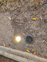
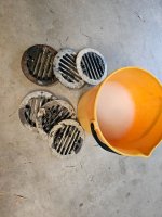
I have rusty in ground landscape light covers that need to be repainted. Very hard to sand all surface, especially irregular bottom narrow fins. Looking for advice. I have 20 and they are very expensive to replace.

You all are experts! Can I soak in something? Acid? Paint thinner?

Edit... Tried the basics wire brush and power drill combo, sandpaper, file

Attachments

  • 20250112_163948.jpg
    20250112_163948.jpg
    1.7 MB · Views: 175
  • 20250112_162405.jpg
    20250112_162405.jpg
    738.8 KB · Views: 64

cascading lm3915's, which precision rectifier to use (90db range)

Ok,

So I have found some LM3915's so i'm gonna get a go at using them.

The plan is building a VU/PPM meter using switching Between Bar/Dot.
So the principle is using 2 precision rectifiers with the correct timing to get VU (average) and PPM (peak hold) ballistics.
If I was using one LM3915 with a range of 30db and a maximum of around 24dbu this wouldn't be a big problem (-6db as lowest led is easy altough I would need attenuation as 24dbu is to large for feeding a precision rectifier with opamps)

Now The plan is on using a range of 90db from -66dbu to +24dbu and in theory it should be perfectly possible but I am a little worried for the precision rectifiers.

-66dbu is around 0.5mv peak and +24dbu is around 17,36v peak so to make sure the rectifiers don't clip I would have to attenuate the signal. Let say we take the signal down to 20dbu maximum (around 11v peak) leaving a little margin.
This means the lowest signal will be around 0.34mv.

I looked a little in the datasheet and they mention this as a problem for the lower leds as there could be 10mv offsets so it's better to keep the same reference and amplifiy the signal for the lower leds.
This would mean the first lm3915 get's it signal directly fro the recitifier then the second get's this signal but with a gain of 30db and the last get's this signal with a gain of 60db.
So far this looks possible altough I would need precision opamps with very low DC offset (ad707 or something like that) and for the lowest leds it would maybe need a zero trim.

Only problem remains the precision rectifier. Is it possible to rectify 0.34mv peak?

Using an amplifier before the rectifiers could be an idea but it also creates a problem. this would mean that each lm3915 has it's own rectifier and if using the PPM's slowly decay it would get weird with short transient signals.

The 90db range is mentioned in the datasheet but no schematics or info is giving. Google also gives a lot of cascading to 60db range but 90db is nothing I could find.

Xsim beginner problem

I've started learning Xsim crossover designer and thought I'd use the factory curves for the KEF drivers I have as a starting point - not ideal I know but I'm not able to measure speakers yet. The FRD and ZMA files seemed to turn out ok, as seen in the attached graph as Blue line S1 (driver only). But the results for the T27 tweeter when I drop the factory crossover in place as Red line S1, is a very sunken curve with 2 big peaks! In fact, this happens even when I replace the Concerto tweeter section with a 104aB section. It must be some very basic error I'm making so can anyone see what it is? The peaks start reducing if I add lots of resistance to the 2 caps, but never even out fully.

Attachments

  • AAA KEF Concerto std Xover.jpg
    AAA KEF Concerto std Xover.jpg
    333.9 KB · Views: 109

Anthology II with CnC routed parts - to do a monstrous roundover or not to do it?

Hi! I'm in the process of planning out Anthology speakers and have a friend who takes CnC orders. The idea is to make the speakers fully out of 18mm plywood or alternatively just plywood front baffles and rest from MDF. The usage of a precise CnC router allows for some very precise roundovers - so I'm thinking how to best make use of it. I have planned something like this:
IMG_5172.jpeg

Which has a 30mm roundover in the woofers and at the top, 60mm roundover in the mids and it goes to 90mm roundover on the tweeter, with an organic transition between these steps. This not only looks incredibly cool on my opinion, but also seems to be the best possible option apart from maybe doing spherical tops as well (but that's much harder). Am I correct in my assumption? Is this a good idea at all or do I run into unforseen resonances with such a design?

Another thing is that this reduces the wall thickness in several places. Should I glue strips at the corners to increase the thickness there?

And lastly, should I round the corners inside the cabinets with putty or something similar? I will be damping the entire thing with acoustilux polyester fabric (or rather a similar product) with 10mm felt beneath that and bitumin mats all over the cabinets.

Thanks in advance!

JFET Cathode Cap Switching

Hi all,

I’m working on a programmable tube preamp. Part of that is achieving some way of switching cathode capacitors with a microcontroller. Jumping past LDRs and Relays due to size I’m investigating the use of P channel JFETs as used in many Mesa and some Marshall amps.

The J175 (rds on max of 125 ohms) is the most common I can see in schematics, though I’ve found a Marshall DSL using J174. The “problem”, if you can call it that, is that the guaranteed Vgs off of these parts is 6v or higher. And a microcontroller is going to be toggling 0 to 5v natively. So they won’t be fully “off” but perhaps they get close enough?

I can use an NPN switch to interface but I have found the J176 which has a max Vgs off of 4v in exchange for a higher rds on of 250 ohms max. So I wired a couple up and collected some characteristic data which is attached. I appraised their switching capability as raw resistance and as a voltage divider since there will likely be a small positive voltage on the drain from leakage through the cap. And in the interest of seeing how good of a transistor switch is need I rechecked the V and R across the FET with a residual .5v on the gate to simulate a weak pull down.

I’m curious if others that have used JFETs this way can comment on their implementation choices, the role of part to part variability in deciding which of these options is best, and if thermal or voltage variation should be of concern. My gut says that as long as the FET gets above, say, 20k consistently that’s a good enough “off” and anything approaching 100 ohms is a good enough “on”.

Spica TC-50 crossover refresh

I have a pair of what I believe are the original version Spica TC-50 speakers. They are a matched pair with matching crossover codes. I have read that the codes indicate specifics of the exact measurements of the parts (i.e. they were matched tighter than the tolerance of the parts). I don't think they sound as coherent as they did 30 years ago when I was running them regularly, perhaps the electrolytics have drifted. I suppose I should measure them.

Here's my question: would it be possible to trim the capacitor values using just a decent quality condenser mic (I have AKG perception 220), a computer and audio interface? I remember that the speakers were designed to be particularly flat in frequency and phase response at the crossover region (somewhere around 1k or 2k if I remember right). In other words, can I measure the crossover accuracy without buying more equipment? (No problem acquiring / compiling open source software as needed.) Thanks for any help.

DIY Sony VFET Builders thread

That was some very delightful news that I received in the wee hours of the morning as I was up for a midnight snack. Many thanks to Nelson, the tireless crew at diyAudio, and some dedicated aluminum smiths at Modushop for making this possible. Now my excitement for the opportunity to build a special amp is changing to anticipation of receiving the kit and beginning the build process.

I'm starting this thread for all the lucky builders who wish to share their process, ask questions and suggest new things to try out. I look forward to reading 6L6's illustrated build guide and plan to document my construction of Papa's version of the amp, plus what I expect to be some wonderful alternate boards that have already been suggested by Mark Johnson and a couple others so far. I may have an idea or two of my own to share as well, possibly just so others can avoid the errors of my ways. 😉

UPDATE: 6L6's build guide is now live

Confused about transmission line theory

I’m considering designing a transmission line. Everything I read says that the length of the line is to be ¼ the length of the “target” frequency. The internet says that this will create a 90˚ phase shift which will cancel out waves coming from the back of the driver.

This makes no sense to me. I reason that, if the transmission line has an open end, nothing is going to bounce back to cancel out any waves coming from the back of the driver. Furthermore, if the waves coming out of the open end of the transmission line are shifted 90˚ relative to the waves coming from the front of the driver, this would only boost the target frequency by 1.41X. It would seem the sensible thing to do for an open-ended transmission line would be to make the line ½ of the target wavelength. That way the wave would come out of the port in phase with the wave coming off the front of the driver.

The PDF and the graph I made uses an example of a driver vibrating at 60Hz with a 1.43m (1/4 wavelength), open-ended TL.
1737419631350.png


It does make sense to me that a closed-ended TL would be ¼ the wavelength of the target frequency. The wave from the back of the driver would travel down the line and bounce back, traveling ½ of its wavelength. It would hit the back of the driver in phase with the wave coming out of the front of the driver – doubling its amplitude.

Yet everything I read on the internet says to make an open-ended TL ¼ the wavelength of the target frequency.

Can anyone figure out what I’m missing here?

Attachments

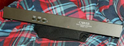
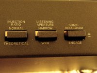
For Sale CarverC-9 sonic hologram rebuilt

Got my hands one of my favorite rebuilds. The Carver C-9 was Bob Carvers most successful design to date. It works with some cross-cancellation, delay, and a small amount of frequency shaping. The end effect when speakers are equidistant from the listener is a surprising wide soundstage develops with the stereo recordings. About 11 years ago, I got my feet wet starting to do minor changes to these units, mainly replacing the RCA jacks since the originals wouldn't allow anything except a skinny interconnect to be used and I mean skinny. It went from that over the years to replacing multiple parts such as electrolytic capacitors and even beyond that. The end result is a unit that performs as new and is unbeatable in its own department. Price is $275 plus shipping. SOLD

Attachments

  • P1010001.JPG
    P1010001.JPG
    234.8 KB · Views: 54
  • P1010001_01.JPG
    P1010001_01.JPG
    271.2 KB · Views: 55
  • P1010002.JPG
    P1010002.JPG
    561.8 KB · Views: 55
  • P1010002_01.JPG
    P1010002_01.JPG
    106.3 KB · Views: 45
  • P1010003.JPG
    P1010003.JPG
    203.4 KB · Views: 42
  • P1010003_01.JPG
    P1010003_01.JPG
    520.1 KB · Views: 38
  • P1010004.JPG
    P1010004.JPG
    253.8 KB · Views: 45
  • P1010004_01.JPG
    P1010004_01.JPG
    409.1 KB · Views: 42
  • P1010005.JPG
    P1010005.JPG
    208.2 KB · Views: 42
  • P1010005_01.JPG
    P1010005_01.JPG
    663.9 KB · Views: 53

Hi Just thought i would introduce myself

Been getting into Audio since September last year after i bought my first turntable. i've been a bit of a techy guy with 3d printers and such but since buying my first turntable i've dove straight in. I don't know what it is but vinyl is so addictive. I find myself trying to create my old CD collection.. I have a passion for vintage stuff now and i'm looking at Tube amplifiers and may in near future have a go at building one. My first Turntable was AT70BTx but have now replaced that with a KD-3100 semi auto DD which i intend on rebuilding and have a Pioneer 1250 on its way which i think will be my main table. I bought some Kef Concerto Speakers which sound really good but the rabbit hole grabbed me and have now updated the Crossovers with new Caps. Now i'm looking to experiment with the crossovers using sim software with a spare set i obtained. There are packages at the door every day lol. the wife isn't happy. haha

2020 Jeff Bagby Revolution Mini SD

Jeff Bagby's Revolution mini (with fabric Soft Dome tweeter)

Here is my build and measurements of the late Jeff Bagby's SB Acoustics Revolution Mini speaker.

For those uninitiated, the Revolution mini was designed by Jeff in late 2018. It follows the classic 1/4 cu. ft. mini monitor LS3/5A size. But this turned out better than expected, does everything from acapella to classical to jazz to rock. I’ve been in this game over 20 years, and it’s just phenomenal.

All the kit components were purchased in one convenient package from Meniscus Audio
(link removed- full disclosure: no affiliation)

The original uses a beryllium dome tweeter SB29SBAC.
I used the soft dome SB29SDAC tweeter, an official design option by Jeff.
However, I used the natural white MW13PNW-4 driver instead, and a slightly shorter cabinet (1") I maintained the original's 7L volume by reducing the depth, but keeping the width constant is very important. A measurement with this tweeter was not released publicly by Jeff, as far as I know, so I've wanted to document it here.

The original beryllium version is smoother in the upper mid and top octave, and the fabric dome version was simply an affordable stand in. Note that the wiggles under 500Hz are due to the effects of Jeff's room.

I never met Jeff, but corresponded with him from the days of Madisound BBS over 15 years.
Always kind, generous, and shared his knowledge. RIP.

1.jpg


2.jpg


Comparison of Jeff's own measurements with Beryllium tweeter (SB29BAC) and my build with soft dome tweeter, overlaid.

1659962691630.png


1662237289342.png


Polar maps:
1662237176128.png


Normalised polar maps:
1662238467515.png


Edit: Measurements in CTA2034A standard aka spinorama added.
Measurements method: quasi anechoic, Jeff Bagby's method- baffle diffraction compensated nearfield merged with farfield. Farfield taken with tweeter 2.4m from ground, on tweeter axis, 2.83V drive level. Microphone at tweeter axis 1m away, rotating turntable)
  • Like
Reactions: Stefano

Optical Bass

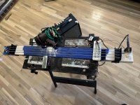
Hello everyone. I made a bass guitar with optical pickups. This was intended as an exercise to familiarize myself with optical pickups and to see if a slide bass would work. I’m happy with where I got with this and am ready to put it to bed. There are others working on optical pickups professionally (Light4Sound) and otherwise (Infrared String Bass). My work was not meant to compete with these, but to simply find out how it all works. I share it here in hopes that some other tinkerer could get inspiration from it, and for myself to put down this project and move on to the next.

I've attempted to attach pictures of the completed bass. I knew I would need plenty of space underneath the strings to be able to experiment with different types and arrangements of pickups. Because of this I made no attempt to give it frets and instead used the limitation as a way to explore if a slide bass would work (spoiler, it didn’t). The bass is simply a 2x4 with some metal bits welded together and some heavy bass strings. The tuning pegs are just bolts with a hole drilled through them for the string to pass before it is wound. The lack of gearing in the tuning pegs made it a challenge to tune, but it was workable.

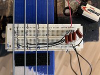
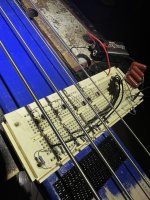
The optical pickup circuit is completely analog and is, at heart, just a voltage divider. The photoresistor and the fixed resistor in series will produce a signal where they meet. I isolate the signal with a capacitor and then sum up the four signals at the end. It’s powered by a 9 volt battery which gives plenty of signal, on par with a traditional pickup. No extra amplifier is required.

The tone is exceptionally clean with no noticeable interference. I’d like to elaborate on how free from interference it is, but it’s difficult to describe the nothingness that is added to the tone. The signal comes only from the vibration of the string and nothing else. One interesting side-effect is that because the pickup only detects the lateral movement of the string, the sound of dragging a pick or a fingernail along the string is muted as compared with a traditional pickup. It is possible that the shadow of the string can either be larger than the photoresistor or misaligned. Both situations cause a portion of the vibration not to be picked up. This can lead to some interesting “optical distortion” tones and I think is worth exploring.

A big challenge with optical pickups is finding a clean source of light. Whatever signal is in the light source will make its way into the pickup. This is extremely obvious with any source drawing power from a 60hz mains outlet. Even LED lights that rectify the mains power do not do so well enough to eliminate the 60hz hum from the signal. Battery power is a requirement. I used a small bright lithium powered rechargeable spotlight that I hung from the ceiling. With the other lights off I was able to get a clean shadow on the photoresistors.

There has been effort made by others to contain the light source and pickup into a single package which has the added benefit of not allowing “dirty” light to be sensed. I made no such effort. I wanted to see the effect of the environment on performance and tone. I think there could be interesting ways to play with the tone by playing with the light source. For example, a fan in between the pickup and the light source makes a neat on-off effect. One thing I wanted to research is the wavelength dependence of the photoresistors. If they are dependent on wavelength then a color changing light source could give an interesting “color” to the tone. While isolating the light from the environment may be a requirement for a professional musician, it should be realized that not isolating the light can be a rich source of novel effects.

As for experimenting with a slide bass I was not able to get the results I wanted. I assumed that I would be able to make some good, if simple, music by using a slide. I wasn’t. I could not get the sustain I wanted and had to use too much pressure on the strings to get any sustain at all. That combined with my lack of slide guitar skill made it extremely difficult to compose anything interesting.

Overall I am pleased with the results I got and the lessons I learned. This project or something like it is well within most people's capabilities. The circuit is simple and the parts cheap. I hope people keep experimenting with this and I am interested to see where the optical pickup goes in the future.

Attachments

  • IMG-1468.jpg
    IMG-1468.jpg
    629.9 KB · Views: 172
  • IMG-1469.jpg
    IMG-1469.jpg
    511.8 KB · Views: 165
  • IMG-1467.jpg
    IMG-1467.jpg
    584.4 KB · Views: 176
  • Like
Reactions: stv and unaHm

Kenwood Bluetooth Firmware updater tools KDC-BT645U

Kenwood Bluetooth Firmware updater tools KDC-BT645U REV 3.06 Bluetooth.
I am trying to connect a iPhone 12 Via Bluetooth.
It seems to connect the Phone / Contacts etc.

But i cant seem to send audio.

Does anybody know if that is a function on this model.

I have a Sony that does it...
It seems odd to me that a High endish, Head unit that has bluetooth, cant receive audio to play music.

I have found there are updates for the Kenwood firmware in a File format that does not seem to be recognized in the Firmware updater app. Setup_OEM
te0916k.krm
kdc-bt645u_fw_y400.ulp

Any Ideas?

Thanks

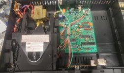
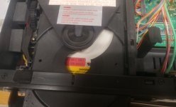
Restoring Philips CD players that use CDM-2 & CDM-4 transports

I'm starting a new project. I have 4 "Philips-based" vintage CD players to restore:

Proton AC-300II
Magnavox CDB480
Mission PCM4000
Magnavox CD2000

New-project_01.jpg
Three of them are currently able to play a CD. The 4th may become a parts donor.

I'm really eager to restore this Mission PCM4000.
Mission_PCM4000_02.jpg
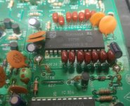
It contains the CDM-2 optical transport and a TDA1541 (no suffiix) DAC. The PC boards appear to have been manufactured by Philips. My example of this machine is dusty & dirty and it desperately needs a new tray drive belt. Otherwise it is fully functional. I'm looking forward to putting this one into my main 2-channel audio system after I finish cleaning/restoration.


The Proton AC-300II is also a CDM-2 and TDA1541 machine.
Proton_AC-300II_01.jpg
Closer view of the Proton's CDM-2 transport:
Proton_AC-300II_02.jpg
The Proton contains a TDA1541A DAC with an "R1" stamp.
Proton_AC-300II_05.jpg
It's only electronic problem is a non-functional 4-digit front panel display. This is a relatively common issue with Philips CD players. And though Proton used a different-looking 4-digit display module, it too failed. A clever diyAudio person researched this and made PC boards for a "new" exact replacement 4-digit display for Philips-based CD players. Details are here:

NSM4202A LED Display Module Replacement for Philips / Sony CDM Transports

I already have the PC boards and most of the parts to put on them. I'll also be checking/replacing electrolytics & solder connections, cleaning everything up, & testing it. It will be interesting to compare the sound of this Proton AC-300II to the Mission PCM4000.

The 2 Magnavox CD players are CDM-4 and TDA1543 machines.
CDM-4-19_01.jpg
Magnavox_CDB480_03.jpg
One has a non-functional main PC board. It gets as far as weakly spinning the disc backwards about 4 turns before delivering "Err" on its display. The other machine has a CDM-4 with no measurable IR light output from its laser diode. I transplanted the good CDM-4 into the machine with a working PC board. Bingo! It's playing.

Standby for more!

-EB

A bit of the Hakuin HPA and a bit of the KISS HPA

Inspired by the Hakuin SE Class A HPA Amp of xrk971 and the KISS HPA of AKSA and Nico Ras I built a kind of mix, BJT only:
schematic.png

Both Hakuin and KISS amps make use of a Sziklai CFP, a fiery combination of a NPN and PNP transistor with a chance of oscillating, especially so because this time I used a faster PNP BJT Q1 as an experiment. To prevent oscillation I applied three methods at the same time:
1. A base stopper resistor R10 of 47 Ohm;
2. Both transistors are placed as close together as humanly possible (for me that is);
3. A ferrite bead at the emitter of the NPN transistor Q2.

I think I succeeded in getting the circuit to behave at the first try. While testing it with open inputs, loose cables and such there was little noise to be heard. In fact it sounds very promising just using my phone as a test source.

R9 is a multiturn pot to adjust the characteristics of this amp:

32 Ohm headphones:
R9 4k THD 0.08%
R9 9.6k THD 0.04%

80 Ohm headphones:
R9 4k THD 0.06%
R9 9.6k THD 0.002%

150 Ohm headphones:
R9 4k THD 0.06%
R9 9.6k THD 0.005%

R9 = 4k, 80 Ohm headphones:
FFT.png

freq sweep.png


Only R4 and R5 become hot so use 5W ones. The heatsink I recycled from an old PC power supply, it gets slightly warm.
Hakuin-KISS - layout.png

componentside.jpg


solderside.jpg

I suspect a circuit like this is vulnerable (soundwise) to noise from a switched mode power supply. Therefor I made a common mode choke from three smaller ferrite rings I glued together, about ten windings of twisted pair from an UTP cable and some other components.
DIY common mode choke.jpg

Attached the LTSpice file.

Attachments

  • Like
Reactions: ElArte

DSP Front End for Plate Amp

Hi there,

I know that this will probably be the nth thread about DIY DSPs based on AD chips. After countless of hours trawling the forum for a suitable design that fits a plateamp application I haven't found the one. So I'm taking the chance that someone could point me in the right direction before I bite the bullit and invest the time to design something from the ground up (or modify an existing design eg. FreeDSP classic or Catamaran).

Requirements are:
1 in (mono) 4 out analog balanced via pins for XLR (in) and JST connections (out).
15V power to run off AUX power supply from amp module
The usual features to take advantage of Sigma studio (USBi, monitoring, etc.)
Distortion < 0.005
Optimised layout for platemounting (perpendicular to faceplate)

Anyone with any ideas?

Thankful for any suggestions or leads 🙌

Cheers.
/M

Martin King open baffle II

Arround 2010 I completed an amp based on LM3886 and was looking for a good speaker. Many friends here in this forum helped me making the amp and finally a great suggestion came from Picowallspeaker directed me to Martin King open baffle. At first the size frightened me. But nevertheless I jumped into it for its simplicity and built one. The details are in the thread Suitable Speakers.

Since then my work and home forced me to look away from electronics. Enjoyed the open baffle for several years and then for a couple of year the music also took a back seat. Termite sneaked in and started eating the baffle without my knowledge. About a month back I tried to put back the system and noticed time has taken its toll on the machines also. Lots of work now.

In the mean time around 2017 Martin King revised his design depending on the full range model used.

At the moment I am now working on this project. Got back my Marantz CD5003 back on its feet. The turn table is alright, the amp is as new as before. The radio FM needs attention as it has gone silent.

The revised crossover suitable for Fostex 103En is done. Only the baffle needs a complete new making. Still looking for material for it to make it better than before. Any experienced suggestion is welcome.

I have a question now. In an open baffle speaker the drivers can be attached to the baffle in two ways. One is place the driver over the hole and another is passing the magnet through the hole and then fix it. In either case I will be curving out the rim of the hole for free flow of the sound waves. My question is which is better/correct sonically. Aesthetically the first option looks better because the screws aren't visible. Thanks for response in advance.

Will post my journey details here.

Thanks and regards
Roushon.

Help with build (bumpboxx freestyle v3s upgrade)

Hi all, hoping to get some advice with amplifier and potentially anything else I may need. I bought this a hear and a half ago. The left side speakers stopped working about a year ago. Fast forward to today...I've taken it completely apart amd purchased new speakers for it.
Subs are skar ix 10 4ohm 10" 200 rms
Mids are skar tx525 4 ohm 80 rms.
In the pic attached from top left are specs on the box on stock condition.
Top right is the amp
Bottom 2 are specs on upgraded speakers.
For giggles I did connect all 4 aftermarket speakers to the one speaker port but it would clip and completely cut out at high volume. Lower volumes sounded good. I want this to be loud and bad ***. Im capable but fairly new to this. So....thoughts?

Attachments

  • 20241215_183043.jpg
    20241215_183043.jpg
    549.8 KB · Views: 71
  • 20241211_154613.jpg
    20241211_154613.jpg
    679.8 KB · Views: 71

Recoton NHT SUB Repair

Hey everyone,
I have this Recoton NHT SUB TWO amplifier with tracking down coverters. It's build the same way as Bob Carvers Sunfires subs. I know they are famous for being hard to repair. This is a tricky one but I feel I am so close to get it purring again and I just cant give up 🙂. Anyone here that has experience with these power tracking circuits?

The negative side is working and I can set idle voltage to -6,5v (between JP2 and SPK+) with RP2. as is recommended, the voltage follows the input signal.

On the positive side I have just 0,630v at idle (between JP1 and SPK+) I have no room to adjust with RP1 if I would go over 0,8v it would fry the MOSFETS.
It should be adjustable to +6,5v
However, The opto couplers seem to work fine. The zeners are feeding them 5.1v and their output is varying with the audio input signal amplitude. Even the MOSFETs are reacting with the input audio signal but not with the same swing.

The positive side goes from 6,86v at idle to 10,52v at 300mvRMS 80hz input. (meassured at S on Q22-Q24)
The negative (working) side goes from -1,86v at idle to -14,6v at 300mvRMS 80hz input. (meassured at D on Q19-Q21) all relative to AGND.

All electrolytes has been replaced and all passive components have been meassured.

The +down converter voltage being 0,6v at JP1 is an obvious problem.

Is the problem for sure in the positive tracker or could it be in the Drive amp section?
Any thoughts on were to focus next or any general remarks would be highly appriciated. I know this is an old amp but it would be so neat If I could get it up and running. 🙂

I have found this thread that helped me alot from 2008

Attachments

Morel CAT328 or Scanspeak D2905/930000?

Trying to decide between these and would appreciate any input from those of you who have tried any of them or both. Or even general experience from using Morel tweeters. Generally they seem very similar and will be used with a 12 dB filter at around 2200hz.
Beyond overall subjective SQ at normal levels I am keen to understand any experience on if any of them would be cleaner and less compressed at higher power levels.
https://www.morelhifi.com/filecont/CAT328-104.pdf
https://www.scan-speak.dk/datasheet/pdf/d2905-930000.pdf

New Passive Preamp project Gray Matter

I recently had a chance to build up a new passive preamp by @audiosteve it's very nice and very straightforward. Works and sounds fantastic. 🙂

It's just a nice little box with an Alps RK27 and three-input selector switch. Front and rear panels are made from PCB material, and with the aluminum clamshell chassis extrusions, the overall package is very solid.

tempImagetyCbQr.gif


tempImageB9gfOq.gif


tempImageIISYhD.gif

Semi Beginner Doing His Best to Eliminate Severe Hum/Buzz

I have the often discussed humming/buzzing amp problem. Yes, I’ve read many of the threads here and elsewhere addressing hum, but none fit my situation squarely enough to solve the problem.

I’ve got 2 Museatex MTR-101 solid state Class A amplifiers fed from a Museatex PA6i preamp. For those who don’t know these, the MTR-101s were a Class “A” amp built in the late 80s. I think they’re fantastic, but they both have a loud hum/buzz that is loud enough to be just audible from OUTSIDE the room with the door closed. This buzz issues from both of the speakers, as well as directly from the power supply areas of both amps.


Here are the details in point form:

Both amps buzz when they are plugged in, but not turned on.

Both amps will buzz, even if they are the only thing plugged in to AC and nothing else (no inputs or outputs are connected).

When I turn them on, the physical hum/buzz from the power supply areas increase minimally to moderately in volume. Then, of course, the speakers also start issuing the same, mostly through the midrange and tweeter.

The house I use them in has a proper and modern grounding scheme. The plugs have been checked for correct ground and polarity. I’m in Canada so 120V 60Hz.

The amps behave like this, no matter where they are plugged in in the house, or even in a neighbouring house

I have replaced ALL the electrolytic caps in the entire system (pre-amp and both mono blocks)

I have replaced the rectifier bridges in both mono-blocks

I have reflowed any suspicious looking solder

DC offset at the amp outlets is only three or four mVs

The amps actually sound very good except for the buzz, so yes, they function as intended, with of course the one exception.

The amps have single-ended inputs

The amps are fitted with 3-prong AC plugs and the AC cable is twisted 3-wire on one of the amps and not twisted on the other amp.

Ground loop may be part of the problem but not the majority. Remember, each amp hums even when plugged in to AC only.

It’s difficult to localize the physical source of the hum in the power supply area but it SEEMS that the toroidal transformer, two covered inductors and a very small transformer on the housekeeping board might all be sources.

I came to suspect DC offset on the AC lines but the problem persists (though admittedly lessened) even now that I have just built and employed three of Sjostrom Audio’s DCT-03 DC traps. (1 DCT-03 for each mono-block and 1 for everything else) All 16 diodes are installed in each.

I’m at my wits end, as the hum/buzz is very loud and I’ve done everything I can think of to address it.

I should note that unfortunately I cannot access or supply schematics for the Museatex equipment.

Any thoughts will be appreciated!


Now an additional but related question. Since I installed the DCT-03 traps the sound has improved in ways other than the slight reduction in hum/buzz. I’m not quite sure what I’m hearing but either the detail and dynamics have improved, or the treble has simply increased. I think I like it over all, but it might also be too analytical and “showy”. Does anyone have an informed opinion as to why these units should have this effect?

For sale (UK only): Rhytmik F12BO w/ A370PEQ3 amp subwoofer

Hello everyone,
Hope everyone is doing well. I'm selling my beloved subwoofer. A rare thing on this side of the pond and am sure there will be interested in a piece of gear like this one. Unfortunately due to its weight and size, needs to be collected. Happy to take visits at any point and no rush.

Details of the subwoofer and asking price, etc here: Bartola website - Rhythmic F12BO sale

Cheers
Ale

Seeking information on the John Koval QUAD ESL mod or how to convert the '57 to 2-way, with no capacitors in the crossover

I wonder if someone on the forum has detailed information on the John Koval Quad ESL mod and would shed some light on how one could re-arrange the '57's crossover/audio transformer connections to arrive at the same or similar configuration. The Koval mod is, to my knowledge, no longer available.

Some background on my plan: Whilst continuing to work on my Acorn build (still ongoing; updates in another thread) I started to realize what an amazing feat it was for Walker to have designed and manufactured the Quad ESL some 70 years ago as a reliable, consistent commercial product. It also began to dawn on me how coherent and musical the ESL '57's midrange really is, and how lucky I was to have enjoyed my '57s for years. Used to take it for granted so when all my '57s finally required a restoration to continue providing services, I kept them in storage without a definite timeline in mind for the rebuild. With the newfound appreciation for the '57 and since I already have the ER Audio re-diaphragm kit, no more procrastination! As for the Koval mod--I first read about it in a reprint of Dick Olsher's 1987 Quad ESL review, and his mention of the mod allowing the '57 "to possess flat response on-axis (within 2dB) from 700Hz clear out to 17kHz" really interested me. Since I have two pairs for rebuild, I plan to convert a pair per the Koval mod if possible, and do a comparison.

The Koval mod is said to convert the '57 from 3-way to 2-way and use no capacitors for the crossover. I presume this means that it feeds the two mid (or tweeter) strips and the treble (or "super tweeter") strip in between with the same signal, and relies on the panel's own capacitance plus the audio transformer's parasitic capacitance for the high pass filtering. However this is just my guess and I have not been able to find more specific information on the Koval mod.

Any information would be much appreciated. Suggestions or ideas are also very welcome.

Ground Loop Breaker, but what's right and what's wrong.

Hi,

I’m living in European and build electronical circuits (power supplies and audio) since about 25 years. I think (or at least hope) I’m familiar with compliance tests and most safety topics to bring a mains powered device to the marked.

Related to audio (my hobby) I had no real issue with ground loops till today, but currently I’m designing a new phono amplifier and like to add a MC option with higher gain. Therefore, I try to do it right and investigate some extra time into the grounding concept. Very often I read, that people recommend ground loop breakers (GLB) as an option. Sure, in a well-designed audio system a ground loop breaker isn’t necessary at all. But I’m tinking about the option to have it in case the system isn’t designed well. 🥴

Actually, I understand the reason why they may reduce some hum, but I don’t understand how they are recommended to build. I read about small resistors between Protective Earth (PE) and secondary GND, because there is no current. I read about ceramic caps, antiparallel diodes, 35A rectifiers as diodes, X or Y-safety caps, but to be honest, I don’t understand why. Placing a safety cap in parallel to a small 100R resistor makes no sense for me, because why “safety” if there is a parallel resistor? I read that 35A rectifiers are recommended, because they have to conduct the false current in case of a malfunction to trigger the fuse before they fail. But this again can’t be a valid safety concept. I actually read, that they recommend to connect PE to chassis using such a GLB! This is against any safety concepts I know and for sure not legal in most countries, but I read about it.

My understanding is, that if the systems chassis in safety grounded, you don’t need a reinforced insulated transformer. The mains transformer itself has to be insulated, so why are these diodes recommended to blow a fuse. It may be wrong, but I thought it’s common and legal to connect the secondary GND directly to PE and it’s not critical related to safety. From a safety aspect, a floating secondary may also be okay, isn't it???

Honestly, I’m confused. I think I don’t need a GLB and try to avoid it and connect secondary GND to safety ground at a star-point or two. But as said, I think about the GLB-option between PE (chassis) and secondary GND, as a fallback option if hum is an issue.

Does anybody understand the safety concept of the GLB. In my understanding a simple resistor with a capacitor should do the same thing. Are the diodes really necessary? If it’s legal to have a floating secondary and it’s legal to connect it to PE, why isn’t it legal to have a simple capacitor between and safe these diodes?

Thanks for any thoughts. I read very much about the GLBs, try to understand and maybe help others (and myself) to make it right. I know that they are built in professional equipment in different manners but what’s right and what’s wrong?

Thank you very much for any helpfull input or discussions to bring some light into this darkness. 🙂

Hawaiian Music Question

Hi everyone!

I’ve been exploring Hawaiian music lately and love its soothing vibe and connection to nature. However, I’m still new to the genre and could use some guidance.

What are some must-listen-to artists or classic tracks that capture the essence of Hawaiian music?

I’m particularly interested in slack-key guitar, ukulele melodies, and traditional chants, but I’m open to modern takes as well.

Any recommendations for albums or playlists to dive into?

Also, if you know of any online communities or resources for learning more about Hawaiian music, I’d appreciate the tips!

Dayton DSP-408 active setup home?

Does anybody have any knowledge of these? I see you can run high level straight into it and then out rca? So can I run in two speakers (3 ways) and out the 4 inputs into an amp?
I’m basically trying to put this before an amp so I don’t have to use individual power for each speaker driver. Not sure if this is possible or not?
Here’s the manual for it.
https://www.daytonaudio.com/images/resources/230-500-dayton-audio-dsp-408-manual(2).pdf
I’m looking to go speakers-dsp-amp-receiver pre outs

My design L20D IRS2092+IRFI4020H 200W8R

This is me a new design of the AMP. He had since the IR company demo version IRAUDAMP7S-200.

It USES the IRS2092 driver IC, and the IRFI4020H special mosfet output

Its power can do 200 W 8 R (+ 65 V). So I call it the L 20 D.

This version after four times improved. Scrap a lot of PCB to attain my design requirements.

In the test of the wave and test performance he almost and IRAUDAMP7 is same.

And before the same circuit design out, but often appear waveform distortion phenomenon.

I'm glad someone can like this design. It is very small, very beautiful. And a good voice, power is big enough.

Attachments

  • L20D-1.jpg
    L20D-1.jpg
    374.9 KB · Views: 19,630
  • L20D-5.jpg
    L20D-5.jpg
    228.6 KB · Views: 17,918
  • L20DX25.jpg
    L20DX25.jpg
    34.1 KB · Views: 17,034

Beware the power strip

Hi Guys,

I've been using a power strip I bought many years ago. It was just a basic model. I few weeks ago the power switch started arching and the 20 amp dedicated breaker would trip. The strip had an Ashly FTX2001; Chevin 3000a and EV AC1 plugged into it for the main system. I of course replace the strip with an extension cord and 3 socket "T" to plug in the 3 pieces of equipment. I immediately notice a small but definite improvement in sound across all aspects. Soundstage got wider; imaging more in focus; dynamics and bass depth improved some too.

Moral to the story, Make sure all power connectivity is solid and switches are performing properly. Anything loose or that sparks should be addressed ASAP. Power connectivity matters.

Need help with choosing budget DAC

Hi all.
As you can see from my previous post on "Introduction" I am a complete beginner in diyaudio.

I had a question about what DAC to buy for my Classix III by Paul Carmody. Since currently I have a really limited budget, I would like to save as much as possible (<50€). Also, do I also need amp for them?

I tried searching for an answer on both Reddit and DIYaudio, but everyone was suggesting DAC's outside of my price range. Also, I saw DIY DAC boards, but again, I don't know whether they will be enough to power my future speakers.

Thanks in advance for your help!

EDIT: Forgot to say that I could increase my budget, if necessary.

Troubleshooting one Hot Tube 300B

I'll preface this with saying that I'm reasonably new at this, and I'm doing the best I can with a multimeter and what little knowledge I have. But essentially I'm troubleshooting an Elekit 8600 where one of the 300B tubes is consistently running hotter than the other. This is a problem that has (maybe) been happening since I built this amp 6 years ago, but the voltages at a few test points fell within normal fluctuation ranges though a few were a little high, but the amp played fine, and I didn't really focus on it.

That said, I started having issues with distortion, and a channel cutting out occasionally (after 4-5 years), until finally one channel would pop and stop altogether. I would swap tubes from side to side, but ultimately it never seemed to change the performance, and once one of the tubes (I think) became damaged, tube swapping didn't help because if it's the tube AND the amp, it becomes difficult to diagnose. Finally, I just replaced the two 300B tubes, (not the ECC82s or the ECC83) with a matched set. and put them on the amp. I turned on the amp and it sounded OK-ished but I noticed one tube seemed a lot brighter. After a minute or so of playing, one tube was significantly hotter than the other (one was measuring 86F and the other was 136F). I didn't let it keep running because I didn't want to damage the tubes, so I shut it off.

So here are the actions I've taken:

1. Initially when I had the problem, I reflowed the connections for the tube sockets and visually inspected the PCB, problem seemed to be better, but after a while persisted, honestly the problems were intermittent anyway, so not even sure this had an impact
2. Retested all test points. All voltages were fine, except for two fairly close to the channel - these were unusually high, but fell within the 10% range of acceptable according to instructions, but by then, one of my tubes were probably fried so I am not sure of the cause
3. Purchased a matched set of new 300Bs - but in my first try one channel got so much hotter than the other, I shut it off
4. Taken apart the amp, to visually reinspect to make sure that I put it together in the first place, resistors, transistors all in the proper place and orientation.
5. I also visually inspected solder joints - and started doing some continuity tests, but honestly don't know how to do this effectively. I have a Fluke 87 Multimeter which I think is a pretty decent machine, but when it came to resistors, it was hit or miss whether the continuity was registering.
6. I took a multimeter and tested each resistor for the correct value. I realize that IN A PCB, the circuit is going to impact how these measured, and some of the resistors seemed way off, but when they were way off, they were off in pairs, meaning the readings were similar channel to channel - which seems like that means they're correct

I've reached out to the local Elekit partner, and he's working to help out, but honestly, I'd love to learn how to understand this a bit better, and I want to see if there are any other common sense checks I've left out. So here are some questions:

1. How can I test, or should I just replace the ECC82s and ECC83 in the amp?
2. Aside from visually inspecting solder joints (they all look fine) - what else can I do to test components here? I have the schematic but would love directionally some idea of potential areas to chase.
3. Can anyone share a good PCB troubleshooting 101 I can watch/read?
4. What other potentially silly or simple thing am I missing here? Could there be some unwanted issue with any connections downstream? Speaker polarity? Pre-amp?

Question about optimizing PFFB for TPA3245

I am reaching out for comments and suggestions regarding the PFFB and the TPA3245 configurations. The goal is to create a hybrid amplifier with tube input stages and a power amplifier stage using the TPA3245 with PFFB. Further assumptions include an 8-ohm load impedance. I am not interested in a race for output power, as, in practice, achieving peak power on the order of 10W is practically impossible since it can become too loud for others two floors up or down, often resulting in a police visit. Please do not comment on this, it is simply the reality. Playing with a maximum power of 10-15W is more than sufficient for an average apartment with speakers that have an efficiency of around 90-91 dB/W.

Returning to substance, I have already explained why the TPA3245 is sufficient (the TPA3244 would also be enough, but the powerpad facing down complicates things for an amateur hobbyist) and why I have chosen 8-ohm impedance. I will inform you about the tube stages, with the first being a regular RC stage and the second being an inverter with split load. Following that, there will be voltage followers using operational amplifiers, which unfortunately is due to the desire to implement PFFB. The driving impedances for the power stage must be very low and, ideally, identical. This is not achievable for tubes without using large tetrode/pentode tubes, which, in my opinion, defeats the purpose.

The choice of tube type is quite straightforward and obvious — subminiature double triodes 6N28B-V from Soviet Union, which perform excellently at low voltages. They are more readily available than Soviet nuvistors 6S63N. Regarding both types of tubes, due to having a curve tracer, I have characteristics in the interesting range of voltages and currents along with matched SPICE models. The gain of the tube stage should have a reserve of 8-10 dB to meet consumer standard requirements - around 320 mV rms. Again, please do not comment on this, I have signal sources that only provide audio signal at that level. Adding a switchable attenuator to the amplifier input is not a problem, so around 100-150 mV rms and 600-800 mV rms. As mentioned, there should be some headroom since the audio material does not always reach an average level of -6 dB (which is catastrophic), and the tube wears out over time.

Now, another aspect is the modulation frequency for the current switches in the TPA3245. Definitely 600 kHz. The higher, the better, since the cut-off frequency of the LC filter at the output can be higher, thus having less effect on the transfer characteristic in the acoustic range. The higher the switching frequency, the more accurately the highest frequencies are reproduced. I am not concerned about efficiency drops; fighting for 2-5% efficiency is pointless. Of course, there is also one argument against raising the switching frequency: the dead time of the current switches. Circuits like the TPA3116 or the newer enhanced TPA3126 allow switching at even 1200 kHz, and I have not observed significant side effects in practice. I assume that the TPA3245 has a more complex PWM modulation scheme. I remind you that the load impedance is 8 ohms; I am even less interested in 4 ohms.

So the first task is to calculate the values of the LC filter components. I took a Q factor of 0.95 as a starting point, meaning a slight "bump" introduced by the filter. In the case of an open output, a resistor of 2200 ohms will be permanently connected to the output. Before the LC filters, I decided to add LC snubbers (10 ohms and 330 pF). The Zobel networks are somewhat "delicate" (1 ohm and 47 nF) because simulations showed, in my opinion, that there is no need for "stronger" ones.

Another assumption is that the passband for a +/- 0.5 dB deviation should not be worse than 10 Hz - 20 kHz. Such a narrow deviation means that after engaging the PFFB loop, the boost just outside the acoustic band cannot exceed 0.5 dB for a resistive load of 8 ohms. The capacitances at the inputs of the TPA3245 can be high since the gain drop of the amplifier inside the loop for the lowest frequencies will generate additional distortions. Limiting the bandwidth from below will occur before the TPA3245 in the tube stage.

A few tests resulted in the values provided in the schematic.

Schemat.png


In the rectangle bounded by the dashed line, we have a simplified model of the TPA circuit, with two added capacitances (C21 and C22) limiting the passband, which is necessary since the bandwidth of the circuit enclosed in the PFFB loop significantly affects the resulting frequency characteristic and has a significant impact on ringing visible for rectangular waveforms.

I plotted frequency characteristics for several values limiting the bandwidth of the TPA circuit. The overshoot does not exceed 0.4 dB, which I consider a very good result. Another observation is that the overshoot varies, reaching a maximum, and then decreases as the bandwidth of the TPA circuit narrows.

Bode.png

Green, blue, red, cyan, purple, gray => C1 and C22 values: 0.1 pF, 1pF, 5pF, 8pF, 12pF and 20pF.

The next step is to calculate the attenuation of the carrier frequency. I achieved a result better than 32 dB for 600 kHz (34 dB). For full output power of 35W, this means that with such attenuation, the power dissipated on the load is less than 15 mW.

LCdamp.png


Now, regarding the rectangular waveform. I assumed very steep rise times of 100 ns. For 8 ohms, the simulation results are excellent.

Overshoot.png

Green, blue, red, cyan => C1 and C22 values: 0.1 pF, 1pF, 5pF, 12pF.

Now for the 2200 ohm load - no connected speakers.

OversootOpen.png

Green, blue, red => C1 and C22 values: 0.5 pF, 5pF, 12pF.


Up to a certain point, it looks good with negligible ringing, but beyond a certain threshold, unfortunately, we move to persistent oscillations. The same is true for the suggested values of the PFFB loop components provided by TI. Analyzing the PFFB publication for TPA3244/45/50/51/55 leads me to conclude that the capacitance introduced into the simplified TPA model in my simulations does not exceed 10 pF.

Now, returning to the passband, for this range, the passband with a 3dB drop ranges from 80 to 90 kHz with a broader bandwidth of the TPA circuit than what results from the 10 pF capacitance. I remind you that for a 0.5 dB drop, we have a passband above 30 kHz. Is 80 - 90 kHz bad? No, it’s very good considering that the drop at the upper end of the passband is significantly faster than 6 dB/oct. Let's be honest; how many people, mainly men over 40, can hear 15 kHz? I bet for a significant majority, 10 kHz is a challenge.

Finally, I will revert to the tube stage. The operating point of the 6N28B-V tubes at a power supply voltage of 52-55 V can be set so that for the second harmonic, the distortion level is in the range of -40 to -50 dB, and for the third harmonic, it is 20-26 dB lower. The remaining higher harmonics should be at least 36 dB lower than the second harmonic.

I also want to criticize the race for the THD+N value. In reality, it is a race just for the noise level. Let's look realistically at listening with speakers. The background noise level during the day in an apartment does not drop below 40 dB (away from a busy street). 30 dB is realistically at night, it might drop to 25 dB. Below 20 dB, there is no chance. The SNR value means that if we add that to the background level, we are almost at the pain threshold. Moreover, let’s also consider how recordings are made.

That’s all for now. I would like to request some substantive feedback regarding the schematic and the simulation results.

Regarding implementation, ceramic capacitors will be C0G, then U2J, and finally X7R outside the audio path. Decoupling the power supply pins of the output bridge in the TPA circuit will consist of two 4.7 nF C0G capacitors plus one 1uF X7R capacitor. Further from the IC, there will be two polymer capacitors of 680u. A bit further, closer to the power supply, there will be two 330-470 uF polymer capacitors. The snubber will use a C0G capacitor, the Zobel network will employ the defined values, and the LC filter will utilize MKP capacitors. The tolerance for ceramic and film capacitors will be 5%. Coupling capacitors in the tube stage will be MKS. Any ceramic capacitors limiting the upper bandwidth will be C0G. All resistors in the audio path will be MELF 1%. Standard thick film SMD resistors are only defining the operating mode of the TPA and used in the converters. The output filter coils are Coilcraft UA8013-AL (this is a critical component and should not be skimped on).

THT components will be the polymer capacitors because the SMD electrolytic capacitor housings are unfortunately not very durable. Additionally, these MKP and MKS components will be THT as well as the tubes, potentiometer, and power-on relay. This relay is necessary because the switching power supply that will power the amplifier will be an external device. This is the best approach, as bringing the power supply wires into the housing along with a huge mess of interference (inverters in renewable energy installations, inverters in household appliances) is something better avoided.

As for this relay, a high-inrush industrial relay rated for 20 - 24 A won't work because welding of contacts is guaranteed in DC circuits with low ESR capacitors like polymer ones. I use pre-make tungsten relays where a contact rated for 16A can handle an average current of 800A for 200 us. They are not particularly expensive and can still be easily purchased (but may disappear as they were mainly used to switch prohibited light sources like fluorescent lamps, sodium, mercury, or metal halide lamps).

The PCB will be a double-sided FR4 laminate with a copper thickness of 70 um, dedicated to the TPA3245 evaluation board heatsink. The cost is significant; since the components alone will exceed USD 700 for a single board ordered from a reputable company (e.g., Eurocircuits and not from China, since you need to order 10-20 to weed out defects and select a properly manufactured one, and they can also add extra VAT and customs duties in my country), that results in about USD 150.Additionally, there will be a housing plus all this "jewelry" of speaker terminals, knobs, etc. This cost can be criticized, I understand, but if I wanted something cheap, I would buy a cheap product from Aliexpress. Therefore, I do not skimp, and instead of ordinary aluminum capacitors, there will be polymer ones in the audio path.
Pioneer SX-870 Receiver (Broken trimming resistor)

Hi All!

First off, let me say I'm a newb when it comes to repairing these, but I'm working on expanding my knowledge to become better (My apologies in advance).

I have an old broken Pioneer SX-780 that I got a decade ago, that's been on the backburner on getting fixed up until now. Taking a look inside, it does look to have some water damage, and bunch of capacitors were blown. Which is a bummer, because the outside case looks almost mint. Just need to clean the dials from some light dirt. Pretty ironic that the outside case is excellent, but the inside bad..
473307208_10231759047013836_885987280341732901_n.jpg


IMG_2890.jpg


There's some rust and corrosion inside, which I've cleaned a lot of it off the board and most of the components. I replaced almost all the capacitors and now, I got the receiver to boot, and clear protection mode. One of the channels doesn't work at all though. I went to go adjust the the DC offset on the board, and one of the trimming resistors just fell apart. I'm trying to find a replacement for it, but I'm a bit overwhelmed trying to find the right part. Any help would be greatly appreciated!

cm1r8nfk78ee1.jpeg


Taking a look at the service manual, I believe this is the part. Could someone help me find a part? Many, many thanks in advance!!

Part No. Symbol Description
ACP-014 VR5, VR6 Semi-fixed 150k

This is the part I need to replace Here:
broken dc switch.png


Best,

Nater

Greetings from the Texas coast. I'm making a custom mixer/amp/receiver with crossovers/bandpasses/inputs, mids, highs, and a sub

Howdy folks. I taught a few semesters of university level E&M labs in a physics department in another lifetime (when I was in grad school). I've become a pretty seasoned roboticist already, but I'm learning about making audio systems right now. One of my startups (http://indiejamland.com) revolves around music, and so I'm making a custom mixer/amp/receiver with crossovers/bandpasses/inputs, mids, highs, and a sub. It will be portable, one piece, and powered by a car battery with solar charging option.

I still haven't finished transitioning my webserver off of the cloud to a physical server, so it's not super fancy yet -- don't judge me. I'm actually making custom hardware firewalls, while I'm making custom audio electronics, along with 10 or 12 other projects, so don't expect my full attention.

Right now, I'm looking for .mod, .pretty, and .kicad_mod files for tpa3221 and lm386, so obviously, in addition to 100W/200W amps, I'm interested in op amps too. I may need more power later on, too, so what's the next step up from the tpa3221?

Also, I'm curious about alternative suppliers. I was doing business with Mouser Electronics, but they went to the dark side of the force, so to speak. Digikey is a reasonable alternative, but I feel like I'm two-timing my fellow Texans by doing business with them.

Before you think, "aw man, we can't just answer all his questions now -- he'll never need us again..." Realize that I'm also here to network, so I may pop in and out here and there in the foreseeable future. Plus, I'm bound to have other questions later -- not to mention, I may actually be able to help you with your electronics projects.

Hypex SMPS 1200A400 powering up delay and failure

Initially it was 5min delay and it became 30-45 min delay until it would not turn up at all. I suppose some caps have failed.
I was reading that people had similar problems with Hypex SMPS and in SMPS1200A700 it is typically c39, c38 caps: 220mf. In SMPS400A400 the problem was also 220mf caps. There is no schematics for 1200A400 so I wander if anybody has similar problem and figured it out what caps need to be replaced? I suspect that these should be caps that I've circled next to the transformer.

Attachments

  • HYPEX bad caps.PNG
    HYPEX bad caps.PNG
    316.6 KB · Views: 47

Affordable TSE PT Option--290CX

Hi,

I just hooked up a TSE-ii 300B that is behaving well with a Hammond 290CX. I'm getting 385-390V B+ with a 5AR4 and a 33uf 1st cap, which was my goal. If you actually download the datasheet, the HV compares a bit higher to the audio series than you might expect because they are tested with 120V on the primary instead of 125V. I imagine the guitar/"lay down" orientation isn't for everybody (and should be isolated from a steel chassis), but they are so common you can save a few bucks.

I found what I think to be 290D2X or other Bandmaster replacement at a used instrument shop for $25 and am going to give that one a try on an SSE board. They don't carry the same price advantage new, though.

Paul

For Sale Meyer Sound ST-410 10" Bass Drivers -Pair

Here's a pair (x2) of lovely Meyer Sound ST-410 10" 4-ohm Woofers that are looking for a good bass cab to really shine or as a replacement driver

I believe they are spares from a theater and appear to be unused, therefore in excellent condition

Superbly made with a cast frame, heavy duty rubber surround, Neodynium magnet, vented pole piece, thick pulp cone with damping coating

The damping material used on the cone tends to pick up dust and the photos amplify the effect. In reality the cones look better than the photos suggest

Used in several Meyer Sound systems including UMS-1P, UPJ-1P

Thanks to the Neodynium magnets they are lightweight, only 2.4kg each

Both drivers have consecutive serial numbers!

Depth is approximately 120mm

Made in USA, rarely seen for sale

I'm thinking USD 550 for the pair plus postage

Cheers, Ralph

Attachments

  • ST6a.jpg
    ST6a.jpg
    296.9 KB · Views: 34
  • ST8a.jpg
    ST8a.jpg
    341.2 KB · Views: 40
  • ST9a.jpg
    ST9a.jpg
    247.9 KB · Views: 37
  • ST10a.jpg
    ST10a.jpg
    213.3 KB · Views: 31
  • ST11a.jpg
    ST11a.jpg
    205.9 KB · Views: 30
  • ST12a.jpg
    ST12a.jpg
    368 KB · Views: 31
  • ST13a.jpg
    ST13a.jpg
    347.1 KB · Views: 36

Need help bass reflex PD18 BR 40

I want to build a bass reflex box for this discontinued speaker, I have been looking for information and I think the bass reflex option is the best fit, but I would like someone to guide me through the design process.

I have been using winisd and hornresp, with winisd I understand myself better, but the port it shows is not front, but rear. So I was wondering if the port speed it shows is real or fictitious, as well as the phase interaction between the port and the driver.

I have also made a small design of a 18 mm birch box, it is the typical L shape with some reinforced areas and the 2 square-shaped ports.

The 2 fundamental questions that come to my mind are:
is the port speed real? since too high a speed implies noises. On the other hand, I read that the port must measure at least 1/3 of the diameter of the driver to avoid distortion, I would like to know if it is true.

The interaction between the port and the driver is not too out of phase in the frequency range to be reproduced.

I will leave more information about the project:
driver precision devices 18 br 40
type of music to listen to: hip hop - drum and bass - reggae from 70s in vinyl record to 2023 digital, also funk, soul... mostly outdoors

Transformer for Soundcraft Spirit M series Mixer with linear PSU - M8 or M12

I have been searching the interwebs with no luck!
Can someone help me with sourcing a transformer for the Soundcraft Spirit M8 mixer.
I attached the schematics for the PSU, unfortunatly there is not much info on the transformer, or i'm reading it wrong

I know the original is torroidal

Aparently the tranformer has 3 secondary windings:
One for the main mixer rails with center tap -17V - 0 - +17V
One for the phantom power 0 - 48V
One for the spdif output 0 - 5V

Thanks for any help!

Attachments

The birth of a DBA system

I am starting this thread, because soon I will move to a new house and set up my horn system again, after a year of living in a rented house with no space to install them. I am fortunate that it will be a dedicated room to enjoy my favorite music in the best way possible, within certain constraints, of course. The properties of the room are not very ideal, as it is a rectangular basement room, with solid concrete walls, ceiling and floor. There is a small room in the back and one access door about halfway. The dimensions are 2,4m ( 8ft) high by 4m (13.3ft) by 10,45m (34.8ft) long. Let's call it a pipe drawer...

The speaker setup is as follows: eight bandpass small subwoofers with single 8" woofers, two lower midbass exponential front horns, two mid-high Le'Cleach horns with BMS 4592ND.
In my previous home, I succeeded to have achieved a proper overall sound, so I know these set of speakers work good together. That room was treated with absorption, diffusion and bass traps at their optimum places, as far as a irregular living room can be tuned.

The new room poses one big challenge among some others: the length of 10,45m (34,8ft) in relation to the other dimensions. So I started to model the room acoustics in REW, trying numerous subwoofer/midbass placements. The multiple subs give me the possibility to use various proven concepts for multisub low frequency applications. While I did not model all variants, none of those concepts are really satisfying in this particular room, but one does. In the end, a Double Bass Array will be the concept of choice to build the system from the ground up.

The advantages from the simulation are clear:

  • Linear frequency range from 30Hz to 300Hz with exellent Group Delay and phase behavior.
  • No resonant behavior of certain frequencies in the bass region and good extension into the lowest frequencies.
  • More even bass sound across the room, as a DBA generates a plane wave without back wall or side wall reflections.
  • Short decay of low frequencies without using extensive bass trapping, i.e. no smearing effects in the bass.
  • No need to fill the room with randomly placed subwoofers (a la Geddes), with the associated cable spagetti.
  • The subs do not take much space and can be placed against the back wall without much cabling challenges.

Disadvantages are also clear, but from a hardware point:

* Need for a DSP and multiple amps, in my case I will need four DSP channels and associated amps. I already own a MiniDSP 8x10HD but the amount of delay is insufficient for this room and I only have two channels left for sub bass. The solution (hurts financially) is to aquire a T.Rack (Thomann) DSP amp, a suitable one would be a 4x250w class D-amp plus DSP build in. This means an extra ADDA conversion after the MiniDSP, as this amp has no digital input, but it is cost effective and for low frequencies, I do not think an extra conversion step hurts too much. With four channels of DSP, one can fine tune the response better than with two channels.

* The back subwoofers do not contribute to the sound as they cancel the sound as soon as the plane wave reaches the back wall, so there are only 4 smallish subwoofers that provides the sound pressure a.k.a. lower efficiency. As I do not listen to ear splitting sound levels, I can get away with this disadvantage. It will take about 100 watts to reach 107dB according to the simulation. The mid-high CD can reach that level with 1W input as the difference in efficiency is about 20dB. No problems here, as I use a flea power 1W tube amp for this horn.

Conclusion up to now: a DBA is the best solution in my opinion when dealing with long, narrow rooms -albeit against considerable costs, but also with savings on the bass trap side.

The picture below is an overview of my simulation with both subwoofers and midbass together, I chose to use PSY smoothing in the left graph, to have a simplified view of what is to be expected. The simulation is without any EQ. EQ'ing will of course be preferable, and possible. I applied a modest amount of acoustic absorpion to the room, but fortunately it does not need a lot of absorption, ergo too much absorption will screw it up. I will continue this thread when I am actually moving in and starting to install the system and make measurements of the process.

DBA simulation overview.png


DBA FR_Phase.jpg


DBA impulse.jpg


DBA Group Delay.jpg


DBA waterfall.jpg
  • Like
Reactions: AllenB

Looking for transistor choice advice to implement Catharsis MKII

Hi All,

Currently I'm testing a new output stage design for the amp that I built more that a year ago. It's been occupying my desk for the past weeks, living on a breadboard, trying to find the sweetspot for thermal balance. My plan was to implement most of it with SMD components and use dual monolithic ones where-ever possible. 1206 for resistors that run cool. Hopefully to safe some space for this overcomplicated design and to minimize offset and thermal drift on Catharsis MKII.

2N5551/2N5401 will be FMBM5551/FMBM5401 or NSVT5551 and their complements.
Sadly I have not spotted a BC550 (BC549 on breadboard) dual smd equivalent so far and I was hoping you'd have some suggestions.

I am considering BC847CDW1T1/BC557... or FMB3904/3906 as twin-standins for the BC550/BC560.

Do you know of BJT's that would perform well at low voltages in the place of the BC550/BC560's for Q18, Q17, Q35, Q34, Q2, Q29, Q1and Q28?

Or do you think its best to just sticking with hand-matched through-hole devices?

Many thanks and cheers,

Ruben
Schermafbeelding 2025-01-21 230520.png

Marshall JCM 900 Reverb Drive Circuit Failure

jcm900-preamp.png

I have a Marshall JCM 900 100W tube amp head from 1990 that likely has an issue in its Reverb Drive solid state circuit.

JCM 900 Preamp Schematic from 1990
/\ The schematic of the JCM 900 preamp especially the "reverb drive" section referred to here.


Troubleshooting Progress
While the amp is on and feeding it a 1khz sine wave, an oscope successfully sees the sine wave up to and exiting the V2a preamp tube and can also be seen after the reverb section of the circuit following the dry path.
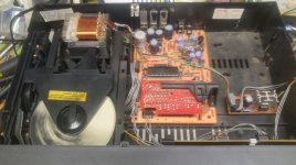
However, the sine signal is lost below the R23 resistor at the start of the reverb circuit (totally fine above it). Above it is a 400mv peak/peak sine wave. I would expect to see at least a 200mv sine wave below R23.

  1. While the amp is off/caps discharged, in circuit continuity and ohm checks using a DMM on every component in the reverb circuit pass/expected (cannot test the caps but none beep with continuity which is assumed good).
  2. While the amp is on, measuring DC below R23, the DMM is registering about -300mv.
  3. While the amp is on, measuring DC right of R28, left of R26, above C17, left of R27, right of R26 all measure roughly -14.25V.

This leads me to assume that "maybe" either R23 or C16 have issues and should be replaced, but since I am not a guitar amp tech guru, before I start desoldering components and adding even more variables/fail points to this issue, I am seeking some understanding and suggestions.

Questions
❔ Should I only desolder components, test them out of circuit and then get them back in as the only option to pursue?
❔ Can/should I see if R23 is the issue by temporarily jumpering another resistor of same/lower value on top of it in parallel?
❔ Can/should I see if C16 is the issue by temporarily jumpering another capacitor of same/lower value on top of it in parallel?
❔ Can/should I do either of the above by snipping one or both ends of the resistor or capacitor and then jumpering or "top soldering" the left over leads with new components and avoid temporarily having to disassemble the preamp board to under solder them?
❔ Is there a way to replicate this issue with a simulation? See my attempt at an LTSpice rendition of this part of the circuit below.
❔ Is it correct that if the reverb drive circuit was working I should be able to see a > 50mv sine wave through its components on a scope but doing so with DC coupling on the scope since the op amps have 12-15VDC on all of those lines?
❔ What affect does having the reverb tank being connected or not play into any values I would read?
❔ Would acquiring a newer/digital scope provide such a difference that I should seek that first?


Additional Info

JCM900-reverb-drive-ltspice.png

Above is an overview of the LTSpice I attempted to create to provide a simulation of this circuit.
The reverb tank is not an exact replica as it has a much higher input impedance, the reverb pot is fixed R, and I took liberty excluding the channel switching IC7 M5201 and replacing that with a single TL701 (see the actual real link schematic above).
With this simulation, I achieve the expected results below and above R23 and above R20 in the dry area.
While the simulation does see -12V in the op amp areas of the drive circuit, it produces a very small and very distorted ac result which leads me to assume the simulation isn't great.
Thanks to Adrian Immler's post "spice reverb simulation?? This is now possible!" for providing a LTspice of a similar reverb tank.

For extensive additional background leading up to this point, please see this post:
Marshall JCM 900 Reverb Issues
I am aware that it is not ideal and borderline/crosses forum rules about not posting two threads about the same topic; however, when I posted to the valve/tube area I did so since a similar reverb thread was in the solid state area and I have a tube amp and other research implied that one of the more common faults with reverb were related to pre amp tubes, so made the assumption that group was appropriate and now see that forum is more specific to hi fi tube amps.

We meet at last

Good evening everyone.
Decided to finally register here after lots of lurking around as a guest whenever diyAudio pops up on a web search.
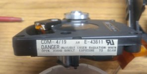
Keeping it short, I'm an electrical and automation engineering student in Tampere, Finland. Been a music and audio geek for years. Gigged in a cover band for 7 of them (a third of my life).
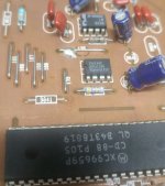
Got heavy into the science of audio technology and anything remotely related. Put together a risky design in the form of Dayton RST28F, SB Bianco MW125-8, and Dayton MX15-22. That came out interesting to say the least.

Now I'm trying to build the ultimate pair of living room floorstanding 3-ways. Going good, more on them on a separate post I'm sure.

Anyway, great to join you.
  • Like
Reactions: stv

Introducing Myself

Hi everyone,

I’m Julius, and I’m from Germany. I’ve been building speakers since I was 12 years old, constantly striving to improve my skills and deepen my understanding of the many aspects of speaker design.

I recently finished my degree in Media Technology, where I wrote my bachelor’s thesis on simulation-based loudspeaker development. During this time, I developed a strong interest in BEM simulations, although my knowledge in this area is still very basic. I’m eager to learn more and expand my understanding.

I’m looking forward to having many interesting discussions about DIY audio and learning from the wealth of knowledge in this community!

Best regards

Julius
Projects by fanatics, for fanatics
Get answers and advice for everyone wanting to learn the art of audio.
Join the Community
507,723
Members
7,885,810
Messages

Filter

Forum Statistics

Threads
406,120
Messages
7,885,810
Members
507,723
Latest member
semajbab