Hi,
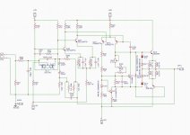
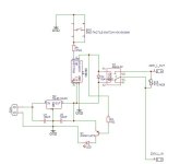
Is there a way someone can take a look at the attached schematic and advise if this will work. Circuit is just the amplification section from a high current Denon amp. I have listed to this amp and the output is just chest pounding. Procuring the output Darlington transistors pair in India is a nightmare,The TIP 142/147 is easily available with less power. Any recommendation/suggestion to modify the circuit to replace the output transistors is a welcome
Is there a way someone can take a look at the attached schematic and advise if this will work. Circuit is just the amplification section from a high current Denon amp. I have listed to this amp and the output is just chest pounding. Procuring the output Darlington transistors pair in India is a nightmare,The TIP 142/147 is easily available with less power. Any recommendation/suggestion to modify the circuit to replace the output transistors is a welcome
Attachments
Last edited:
the base of Q315 is also connected to the base of Q317, the vbe multiplier. looks like a schematic error. 3 subsequent differential pair stages will be difficult to stabilize.

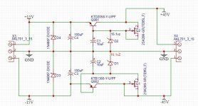
Firstly thank you so much for the valuable feedback from everyone. I have redrawn the schematic and renamed the components. Also corrected the error as pointed out by Basreflex. Few missing components have also been added with in the amp section. Attached is the new schematic. Between TIP 142/147 and 2SD2083/2SB1383 the major difference as I understand is the current rating is there anyway we can modify this circuit to include the TIP. I like the idea of using the Mosfets at the output however lack the skills required to implement such modifications. Appreciate all the support.
Attachments
It is always a good idea to place the vbe trim pot in the bottom leg of the divider, in case of a lost contact of the pot wiper.
Those Denon amplifiers are intended to use high speed output devices. My personal experience with TIP darlingtons is that they “work” well enough in the older Lin and Philips topologies, but in anything more advanced (with higher open loop gain) they give you grief. You may be able to cripple the circuit and crash it’s loop gain at high frequency enough to make it stable. You might not. Distortion (esopecially crossover distortion) will be far worse. You may or may not care. If you are looking for something that “pounds”, it may have more to do with things you don’t see in a schematic. If you wanted an amp for the purpose of delivering energy (as opposed to hi fi reproduction), and what you HAD (or could get) were TIP142/7 I would do things differently altogether, rather than copying this amp.
profusion.uk is selling KTB2640G-Y and KTD1640G-Y 150V 15A fast darlingtons with good safe area used in similar Denon circuits. Use site search function to see discussion of KEC parts here over past decade(s). Also input, vas and drivers similar to discontinued Sanken, Toshiba and Fairchild parts.
Thank you all for the valuable suggestions. I can see availability of transistors on Ali express, this site is banned in India besides there is no guarantee if these transistors are genuine. At profusion.uk it says out of stock. Lets suppose I get the output transistor would this circuit work. I understand it is really not worth pondering over this circuit due to component nonavailability. I worked on this is because of the power and clarity it offered for the size. I will attempt to search again and check availability
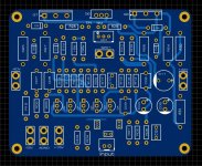
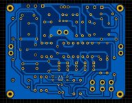
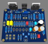
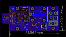
I have placed the order for the KEC KTB2640G-Y and KTD1640G-Y 150V 15A fast darlingtons. Hopefully will receive the same in sometime. Meantime I have worked on a PCB for this amp. I am not a professional PCB designer, but I do make them for simple circuits. Kindly let me know if the attached design will work or if there are some modifications required to be done. Appreciate all the help..
Attachments

Hi Techinvoke,
I would have followed the advice wg_ski gave you. Drivers and outputs instead of a darlington set. Hands down.
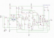
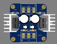
In your power supply, put a place between the source and drains of your current sources for a resistor so you can set the proper current to compensate for characteristics between devices. Your front end won't need the reverse biased rectifiers. You used a zener symbol for a regular diode. 1N4001 would have worked fine in that application (but they are not needed). You could put a rectifier between the input to the regulator and main supply with a cap from collectors to common. Gives you some isolation when you have it cranked. It may also help keep the voltage amp alive when you power off.
I would have followed the advice wg_ski gave you. Drivers and outputs instead of a darlington set. Hands down.
In your power supply, put a place between the source and drains of your current sources for a resistor so you can set the proper current to compensate for characteristics between devices. Your front end won't need the reverse biased rectifiers. You used a zener symbol for a regular diode. 1N4001 would have worked fine in that application (but they are not needed). You could put a rectifier between the input to the regulator and main supply with a cap from collectors to common. Gives you some isolation when you have it cranked. It may also help keep the voltage amp alive when you power off.
As already mentioned, if you can find them, you can keep similar original FT parameter with the a pair of drivers and output transistors such as:
NPN: MJE15032 (Driver) + 2SC5200 (output)
PNP: MJE15033 (Driver) + 2SA1943 (output)
With these pairs you get a nice FT = 30MHz.
TIP142 and 147 have FT = 4MHz.
The original Sanken has FT = 20MHz.
I live in a peripheral country, where good components are difficult to get, but I can easily find these pairs of transistors.
Just check if they are not counterfait - Last time I bought them, before using, I made the basic tests to check such as maximum VCE, maximum IC, gain, SOA, frequency response etc.
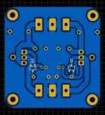
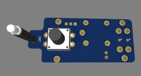
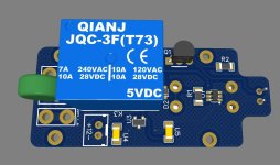
For those looking for a small latch switch to turn on/off here is probably the smallest circuit. The YN810, HR810, available in SOT23 package. This chip is used in torch/head light as an on/off switch. Circuit is not mine and I have not tested this owing to non availability of this chip in India. You can procure them from Ali Express. I have however made the PCB for it. A single unit that could be mounted as a power switch for amplifiers etc.
Attachments
Which PCB design software do you use?I have placed the order for the KEC KTB2640G-Y and KTD1640G-Y 150V 15A fast darlingtons. Hopefully will receive the same in sometime. Meantime I have worked on a PCB for this amp. I am not a professional PCB designer, but I do make them for simple circuits. Kindly let me know if the attached design will work or if there are some modifications required to be done. Appreciate all the help..
I also put a fixed resistor in series so you can’t turn it down to a dangerously low resistance.It is always a good idea to place the vbe trim pot in the bottom leg of the divider, in case of a lost contact of the pot wiper.
Kindly share some more information so that I can amend the schematic. Thank you...I also put a fixed resistor in series so you can’t turn it down to a dangerously low resistance.
Something like this. You put the pot on the lower side and a fixed resistor in series with it. You want to size that resistor so that you get a very high bias current when you turn the pot down to 0ohm, but not enough to blow up the amp. I think I sized mine for 10W max idle dissipation, which is WAY more than I would ever want in a Class AB, but hopefully not enough to blow things up. You can calculate the value of the resistor, but I found it easier to just use LTSpice and a bit of trial and error.
This is an example from an amp I designed a while ago. I think I would have made the resistor values lower if I did it again. You will have to adjust the resistor values to suit your design.
Also, make sure your VBE multiplier is mounted on the same heatsink as the output transistors to avoid thermal runaway. That's the whole reason I went with a BD139 here: It's easy to mount on a heat sink!
- Home
- Amplifiers
- Solid State
- Need help with this audio amplifier. If this circuit can work?