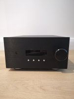
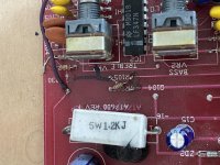
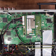
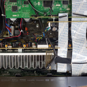
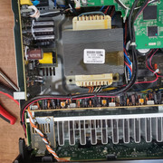
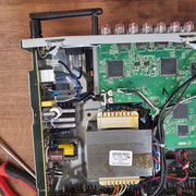
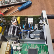
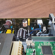
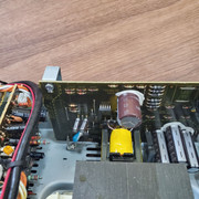
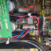
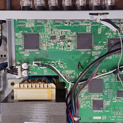
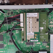
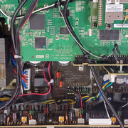
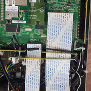
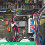
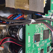
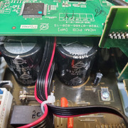
Sonance 1250 mk 2 blowing fuses

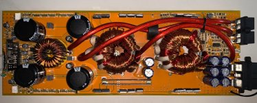
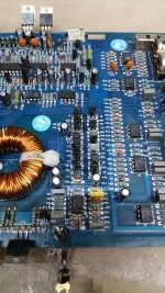
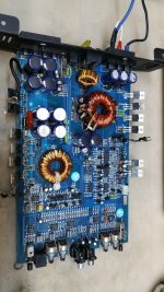
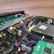
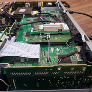
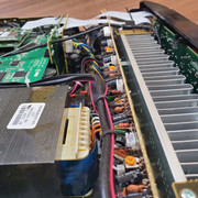
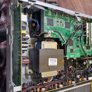
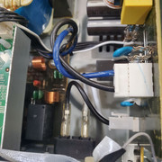
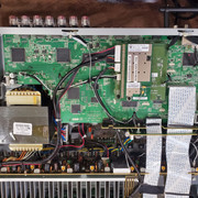
I have a sonance 1250 mk 2 that blows fuses as soon as it's powered on.

Apparently Sonance typically only does repairs at the factory, they do not publish service manuals. The problem is that round trip shipping alone would probably cost more than the amp is worth.

I'm looking for advice on what to do with this amplifier. It would be a shame if it ended up in the landfill. I have some electronics skills, but without a schematic I would not know where to start with fixing it myself.

Fane Colossus Prime 18XS experience?

Hi DIYaudio

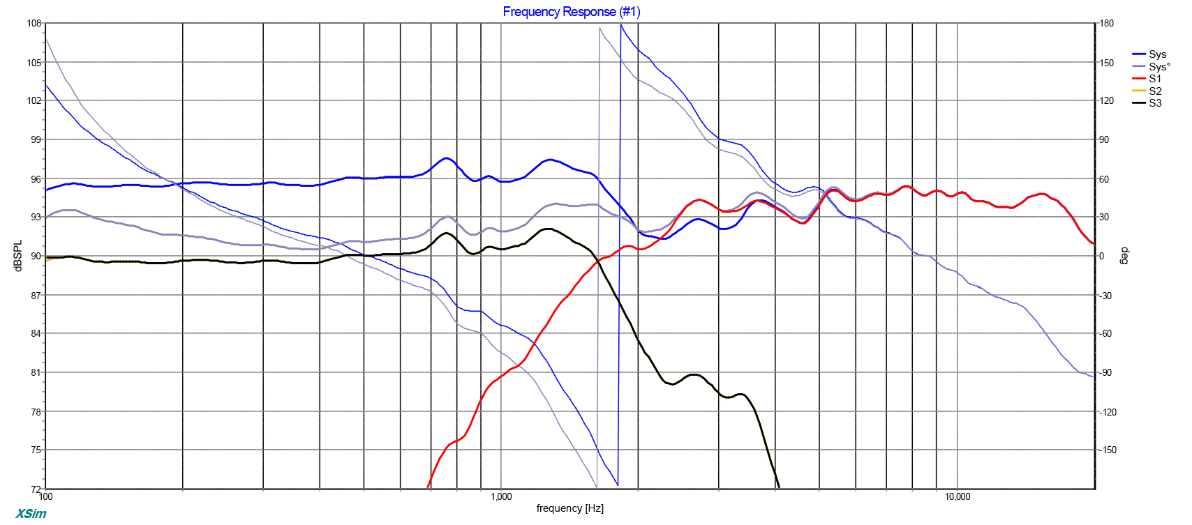
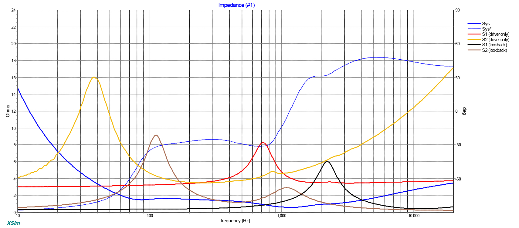
As the title suggest, I am looking for someone who has experience with the Fane Colossus Prime 18XS driver. The sensitivity chart says 100db which I'd like to believe, but since these charts usually hold some marketing info that does not match reality, I'd like to know if anyone can confirm this.

It'll be for a sub, but I'd like to be sure about the numbers before I buy it.

Thanks a lot! 🙂

Zener diode failure?

Possibly a dumb question, what can cause a zener to fail?
The particular diode in question is reading 2 ohms in both directions and is part of the output drive voltage regulation (possibly not the correct term) of an Alpine MRV-M500.

It took me ages to figure out why I only had a drive signal on the high side output and not the low side. There were a few other bad parts in the output drive section as well but they were fairly easy to identify.

Attachments

  • IMG_6274.PNG
    IMG_6274.PNG
    363.9 KB · Views: 135

Impact of high voltage on turntable motor

I have a Pro-Ject Debut Carbon with the AC motor. I just noticed that the power supply provided is putting out 19.4 volts AC according to my DMM. Per the TT manual (and the PS Label itself), it should be 15 volts AC. It’s a synchronous motor, but does the higher voltage impact the motor in a way that affects performance? Speed seems fine, but what about hum or vibration? Seems pretty far off in voltage.

Just curious.

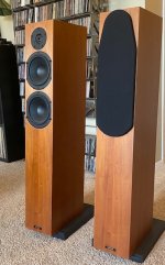
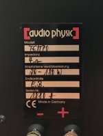
FS: Audio Physic Tempo III

Original owner, non-smoker. Great set of small tower speakers. Really excel at imaging, and surprisingly good bass. Condition probably 6/10 with some small chips in, and rounding of, the corners, but functionally all good and work perfectly. From listening position they look mint. Looking for $800 OBO, local pickup or delivery possible in Denver area.

Attachments

  • IMG_6059.jpg
    IMG_6059.jpg
    115.9 KB · Views: 176
  • IMG_6061.jpg
    IMG_6061.jpg
    81.6 KB · Views: 161
  • IMG_5044.jpg
    IMG_5044.jpg
    521.1 KB · Views: 161

Stub at velocity max, at a mid band qw length and shaped/stuffed, long series exit

I’ve put this together and cut wood. But there seems a lot of variables and fun things to see here and I think I should ask about some instead of assume.

I’m at the end of a full qw pipe length based on Fs, Qes and Vas. (I actually used a respected members math to start from). 200cm2 at 230 cm is a bit of a fudge factor from 185/190 in the math as a response result was skewed a bit toward a healthy bass extension and knee area.

I then placed this into a tapped pipe scenario and an offset stub at velocity max used at the qw pipes end before the motor side tapped mouth entry and a long series exit and the shape to support it all. And even a bit of a boost cause I’m greedy.

Can I get a few fact checks and critical reviews so it’s clear I’m in the correct frame of mind as mechanisms fir what I’m looking at.

I’m sim and reality. First the sim: I’ve left L12 and L45 untouched. I’ll show why in a bit...

Attachments

  • image.jpg
    image.jpg
    1,010.4 KB · Views: 98

Modelling a transistor's behaviour.

I have a wide gap in my knowledge of electronics, and this, concerns modelling a transistor's behaviour. While reading, I encountered the Eber's Moll transistor model, specifically, the formula:
Code:
Ic = Is[exp{Veb/(kT/e)} - 1]
Where:
Ic is collector current
Is is saturation current
Veb is the base emitter voltage
 
k = 1.36e-23 (Bolzmann constant)
T = 293 for room temperature at 20C
e = 1.6e-19 Coulombs.

I tried to apply this model to the 2N4401 transistor but failed to reconciliate it with the model used by LTSpice.

I am perplexed, because models, are expected to be representative of what they model.

Back when I was still an adolescent, many many years ago, my first serious reading in electronics used the h-parameters and it was very tedious with loads of formulae. What I am reading now, is claiming one does not need h-parameters as there are better models which are easier to apply. The author suggests the Eber's Moll model, as stated before.

Warning; Autotech horns

Ive had real problems with this company. I sent them a bank transfer for GBP £1100 for JMLC 200T horns and they claim the money has not arrived. I followed up with my own bank (Starling) who have a SWIFT MT103 record to show it has been sent and arrived at the receiving bank. After days and days of email ping pong the proprietor refuses to investigate and denies the deposit has been made. Im now out of pocket with no recourse. Id suggest you treat any transactions with this company with huge caution - id insist on using only fully transparent, auditable and reversible mechanisms in future - if at all. All very disappointing.

Any ideas on a reputable horn manufacturer?

Is the length of NFB loop on a pcb are so important ?

Hello

Is the length of NFB loop on a pcb are so important ?

From 4706 Gaincard sakura systems web page, "...the length of NFB loop creates a time delay between the original and the return signals and allows noises to enter. To take full advantage of NFB, we shortened the length of the feedback loop on Model 4706 to 9m/m, which includes the length of the resistor. We achieved this breakthrough by utilizing power IC and intricate point-to-point hand wiring."

This Sakura text are for his Gaincard chipamp amplifier, but it should apply to all audio amp.

For myself, I try to keep the NFB loop short on my pcb.

In audio frequencies, the length of NFB loop should not be so critical, but I may be wrong.

Thank

Bye

Gaetan

Fender Deluxe Reverb II (Need help!)

Hello all! Brand new here. I am an experienced guitarist and amateur luthier, but I am new with working on amps. I am in search of some help on how to fix this amp, and which tubes I should buy!

I recently acquired an original Fender Deluxe Reverb II. Before and after an in-depth restoration (cleaning-wise), I noticed that the clean channel was not working properly on the amp. The gain channel, when you pull the channel switch, seems to work fine. There is a decent amount of crackling and such with any type of playing through the amp.

For a brief history of the amp, it was owned by the brother of one of my dad’s friends whom was a musician before he passed. This friend had lent me a ‘79 Fender Stratocaster a year ago to restore and he ended up letting me play around with it for awhile as a thanks for bringing the guitar back to life. All of the music gear owned by the friend had been sitting for years and years, I assume untouched.

Do I need new tubes? Is there any further troubleshooting I should do before buying tubes? I am going to try the wooden spoon trick on the amp today. Any input helps. And if I have to upload a video showcasing the issue (if I can) I have no problem doing so. Thanks!

Pi 4 nice enclosure required

I've been pottering around with streamers and I've decided the Pi4 with Moode is the way forward for me.

But as it's part of my HiFi setup the polycatbonate 'case' is a bit cheap, and I'd like the space to set up a good power supply instead of the wall wart and possibly (or likely) an USB reclocker of sorts.
So I'm looking for a good, stylish and solid enclosure for further developments.
I'd prefer an easily accessible supplier with reliable shipping to Europe.
No BPC.


Any recommandations ?


Thanks, Pete

Yet another Tivoli Model One troubleshoot...

Hi,

I've reviewed other posts on the forum for the Tivoli Model One but these are nearly all focused on the issue of hiss/scratchiness and tuning slippage in the device and diagnose cleaning/replacement of the varicon in the unit.

I'm getting a different issue so, before I rip it open, I'm keen to get some advice on possible causes. The radio now emits white noise on all input settings (AM/FM/AUX) at low/med volume. When the volume knob is turned up very loud the noise dissipates and the audio signal comes through. Switching internal/external antenna has no effect. Listening through the headphone jack doesn't produce as much noise at low volume but still requires volume to be at top level to let the audio come through.

Given the variability, is this pointing to shorting in the volume potentiometer at minimum settings or are there other things I should look at (e.g. cracks in PCB/bad solder joints). It basically started happening "overnight" and the unit wasn't dropped or damaged in any way.

Any help appreciated.

Multiway xover question

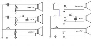
In the picture bellow you will find a simplified schematic of a 3Way xover of second order
The left approach is the more classic while in the right approach which i have seen in a few manufacturers, tweeter network is fed from the mid xover at the point where already mid net work cleared out all the bass

from electrical POV obviously the tweeter network will have a far easier job to do since most of the job is done by the mid network

That's it ? i don't think so
so please comment with pros and cons and why

thank you

Attachments

  • 3wxover.jpg
    3wxover.jpg
    141.8 KB · Views: 248

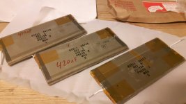
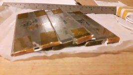
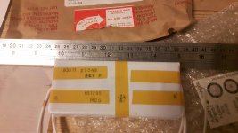
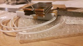
Help id mystery capacitor

I got these assisting clearing out a storage. There was lots of military parts as well as all kinds of electronics. Anyways these caps are a bit mysterious. They measure dead flat up to tens of MHz.
I took one pack apart and there are two caps a little fatter than the last one. The bigger ones measure a tad over 400nF.
Are they mica?
Guess I will need to build a new phono pre or something to try these out.
Thanks for help. I have tried googling and no luck.

Attachments

  • 20200906_014852_resized.jpg
    20200906_014852_resized.jpg
    825 KB · Views: 163
  • 20200906_014834_resized.jpg
    20200906_014834_resized.jpg
    836.5 KB · Views: 147
  • 20200906_015129_resized.jpg
    20200906_015129_resized.jpg
    807.4 KB · Views: 134
  • 20200906_015141_resized.jpg
    20200906_015141_resized.jpg
    879.3 KB · Views: 133
  • 20200906_015207_resized.jpg
    20200906_015207_resized.jpg
    861 KB · Views: 128

Preamp questions

Hi,
Been lurking on the forum and doing some builds for a couple of years. I have built a B1 (no korg) and a pair of ACA amps. I am currently looking to upgrade my preamp and am struggling to find good comparisons between the B3, B1 Korg, and wayne's linestage and the ACP+. I like the idea of a headphone amp too, so the ACP+ and/or a wayne's linestage with Whammy sound intriguing. Reading between the lines it sounds as if the very best would be the wayne's linestage and a whammy. How does that compare to an ACP+? How does the ACP+ compare to my B1? I realize it is my ears that are the final judge, but would be curious what other people think. I am currently using a pretty good class D amp (250W a channel, Red Dragon) and some Spendor speakers. i have also kicked around the idea of getting an old Threshold PRE (SL10) and recapping it. My mind is running around in circles.....thank you for your help.
Tim in Seattle.

ModuShop text printing tips?

I am close to placing an order for both 2U and 4U 10mm aluminum faceplates. I have already made drawings that they can use to do the CNC work, but I am a little stuck on making a drawing that they can use to do the print (here is the page describing their print service).

If someone here has already submitted a drawing to them for faceplate (or rear panel) printing, would you mind sharing it with me so I can see what it is supposed to look like? Also, is there any free software I can use (e.g. Gimp) to generate the drawings?

The problem I am imagining is that I have made the CAD drawings in Fusion 360, but the print files (CDR, AI or EPS?) will come from different software, and it will be difficult to confirm the text is aligned with the knobs, switches, etc.

Let me know if you have any tips or links to tutorials, etc. I am also looking at Front Panel Designer (from frontpanelexpress.com) to see if I can generate/export both drawing types with the same software.

Thanks in advance!

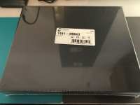
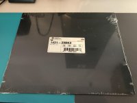
FS: New Hammond 1441 Black Steel Chassis, New Hammond Transformer Covers

IMG-1002.jpg IMG-1001.jpg

Brand new Hammond steel chassis and cover, still in shrink wrap:
  • Hammond 1441-29BK3 black powder coated chassis
    [*]12"W x 10"D x 2"H​
  • Hammond 1431-30BK3 black powder coated cover
$40 plus USPS Flat Rate Priority Mail shipping in continental US.
PayPal accepted

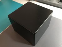
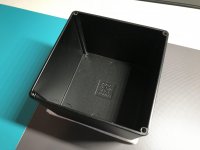
IMG-0997.jpg IMG-0998.jpg IMG-0999.jpg

Brand new Hammond powder coated transformer covers:
  • 4.7"W x 4.7"D x 3.5"H
  • Based on Hammond 1590 die cast Aluminum enclosures
$30 plus USPS Flat Rate Priority Mail shipping in continental US.
PayPal accepted

I2S clocking for active speaker DSP board

Hi All,

I'm working on a reasonably affordable AD-DSP-DA PCB for use in speakers with Hypex NCxxxMP amplifier modules.

Currently I'm stuck at the I2S clocking part of the schematic.
I'm planning to use a ADAU1452 DSP as master, supplying BCK and LRCK to 1x AK5572 AD and 3x AK4490 DA. Considering cost vs. specifications I have found the Crystek CCHD-575-25-24.576 oscillator to be suitable.

The ADAU1452 has a MCLK input and a CLKOUT output that can drive MCLK to multiple IC's. CLKOUT is after a PLL and devider/multiplier. The only spec Analog Devices gives about the CLKOUT output signal quality is a cycle to cycle jitter of between 12-109ps. This is worse than what the Crystek oscillator can do, so it would make sense to me to directly supply MCLK from the crystal to the AD and DA IC's.

LRCK, BCK and Data out will still be clocked through the ADAU1452 with it's jitter. I think those should then be reclocked to the Crystek to improve jitter. Sofar I've seen two methods, using FIFO buffering or using flip flops. The former is too complex and expensive for me, so that leaves the latter. One thing I wonder about the flipflop method; is it possible for a data edge to jitter right before/after a clock edge, causing some data edges to be missed for one cycle?

Will this topology work, and will it be an improvement over routing I2S straight between AD-DSP-DA?
Is the flip flop reclock method the way to go?

I'm hoping for some pushes in the right direction. All suggestions, pointers on anything that I've got wrong/missed will be welcome.

Thank you for taking your time to read my post and/or reply.

Parts that I'm planning to use:
AD: AK5572
DA: AK4490EN
DSP: ADAU1452
Clock: Crystek CCHD-575-25-24.576
Opamps: LM4562
Opamp + supply: LT3045
Opamp - supply: LT3094
Other supplies: LP38798

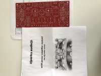
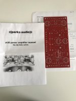
FS: Shannon Parks DIYTube ST35 (Dynakit Stereo 35) Amp Board, Rev. E

SOLD: Shannon Parks DIYTube ST35 (Dynakit Stereo 35) Amp Board, Rev. E

Up for sale is a brand new DIYTube ST35 (Dynakit Stereo 35) amplifier board, Rev. E (I believe this was the last revision before production was discontinued). This high quality board comes with the detailed manual that designer Shannon Parks included with the board.

IMG-0981.jpg IMG-0982.jpg

$50 including USPS Flat Rate Priority mail shipping within continental US. PayPal accepted.

P.S. I also have an original, working condition Dynakit SCA 35 integrated amp with fully working PA774 power transformer and Z565 output transformers. Price for Dynakit SCA 35 is negotiable.

With the DIYTube board, this would make an incredible Stereo 35 6BQ5/EL84 tube power amp amp using original Dynaco iron.

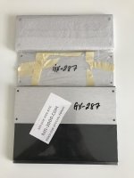
FS: Brand New HiFi 2000 Galaxy 2U Chassis, 10mm Aluminum Face Plate

SOLD: Brand New HiFi 2000 Galaxy 2U Chassis, 10mm Aluminum Face Plate

I am selling a brand new Galaxy 2U chassis with 10mm Aluminum face plate. It is still in its original packaging. Long before the diyAudio store starting selling chasses from Modushop in Italy, I bought two of these chassis instead of one in case I had another project that could use this.Complete with assembly hardware and extra 3mm anodized Aluminum face plate.

Reference:
Galaxy 2U w/Aluminum Covers – diyAudio Store

$60 including USPS Priority Mail flat rate shipping within the continental US.

IMG-0983.jpg

FS: NC400 amp modules

Got a pair of these going spare with the PSU cables and some bare hypex XLR input cables. The PSUs have gone bad, but the amp modules are fine.

They currently have the gain resistor removed (so running 11db), but the resistor can be put back in place if full gain is required.

If your running your source / preamp closer to -50db than -30db and especially if using a digital vol control, you may be better off at 11db gain.

£250 for the pair ono + p&p. Can ship to UK, EU or USA.

Picture of modules + cables now attached.

Attachments

  • IMG_20200906_184954.jpg
    IMG_20200906_184954.jpg
    984 KB · Views: 310

Advice of Rotary Switch for switching sources

Hi, first post.


I am making a complex PC control panel for my desktop in my workshop for controlling many functions one of which is Audio.


I will have multiple inputs from different mics and other equipment, all these being stereo.


So, to switch all these different mic inputs I intend to use a rotary switch.
This is where I am lost, so let me explain and correct me where necessary. Thanks


4 mic stereo inputs (left,right and gnd) so do I need a 3 pole 4 way rotary switch or something else as I have read on this site I can connect all the gnd's together and use the unused pole to show an LED indicator to which inputs are being used


I struggle with switches and I do not want to go and buy a lot of them if they are the wrong types.

Soundmagus PK1500.1 output section problem

Hi guys


I'm working on this soundmagus PK1500.1, which came to my workbench with the output mosfets shorted, the 10uf 100v non-polar electrolytic capacitors blown, in addition to the 2200uf 100v blown, the 1uf 100v polyester capacitors blown coil output shorted and resistor R294 open.


Once the board has been cleaned and all the new components have been installed, in addition other soundmagus vs1500 output coil, the amplifier has a standby consumption of more than 20 amps, even short-circuiting ALL 640n of output in less than 2 seconds. In addition to high frequency noise in the output coil. Something very strange.


But by removing the 50ohm R294 resistor, the draw drops to 1.4 amps, which is normal for this amp. The output pulses appear very clean and stable at 122khz, but when I connect a speaker to it, it has very unpleasant noise and DC voltage spikes.


I have reviewed solderings, reviewed all the existing diodes and transistors on the board, resistors and some ceramic capacitors.


It's a very strange problem that I never get to my table on any other amp.


Does anyone have any idea what may be happening? I've been working on it almost daily for more than 2 weeks and I can't find the problem.

Thanks

Attachments

  • pk1500.1.jpeg
    pk1500.1.jpeg
    201.2 KB · Views: 163

Helmholtz resonance (not for dummies)

Hello everyone,

is there anyone able to help me understand this phenomenon in depth?
I have been reading quite a lot, talking to phisicists, engineers, professors, and all come up with different explanation or theories (most of them contradictory or not really logical). Since when physics has been so little objective? 😕🙁

So here it is my doubt.
Any cavity with a hole and a neck is (and acts) as a Helmholtz resonator. Every and each single source I found describes the mechanical equivalent of this element (mass-spring-damper oscillator) in order to explain its behavior and come up with the final resonance frequency, providing the classical example of a bottle producing its characteristic sound when blowing across its neck.

However:
1) almost no one explains why this sound is produced only when the source is coming at a specific angle (if you just generically blow into the bottle it comes no sound out of it). This means the generic explanation is somehow incomplete without this additional information.
2) no one explains why the very same element can be used either as a resonator (e.g. bottle sound resonance as per point#1, enhancing the sound of a guitar body, allowing for the bass reflex effect in a loudspeaker cabinet) or as a selective noise filter (e.g. bass traps, acoustic panels, attenuation elements in engine intake systems)

In particular:

1) music applications: a guitar body is a Helmholtz resonator. If we neglect for now the small elements within the body, only affecting higher modes, the whole body acts as a Helmholtz resonator (for example ~15L cavity, 20mm neck length, 100mm neck diameter) leading to a first resonance frequency of ~156Hz (considering the end corrections) corrisponding to a Eb3 note.
If we consider the body as a resonator, we should then expect a resonance at that frequency enhancing the notes around Eb3.
If we consider the body as a sound filter (having a Transmission Loss peak at that frequency) we should expect a great attenuation at the same frequency.
A string instrument soundboard represents an impedance matcher between the strings and the outer air, allowing for a high-efficiency energy transfer from the source (the strings vibrating) to the receiver (our ears).
However, in practice, we all know that the sound box still allows for additional sound enhancement, across the whole frequency range of the instrument. This cannot be due to the Helmholtz effect of the box, since it would only enhance a narrow frequency range (156Hz in my case). This seems more due to a phenomenon similar to the bass reflex effect (see later).
Why cannot we then see any real effect from the soundbox cavity?

2) audio applications: the Helmholtz principle is used in the loudspeaker cabinets desig when the bass reflex effect wants to be exploited. In this case a phase inversion of the source pressure wave (the vibrating speaker diaphragm) occurs at the Helmholtz resonance, allowing for a constructing interference outside the cavity, hence the +3dB improvement given by the cabinets with bass reflex. However, this phenomenon can occur only after the Helmholtz resonance frequency, therefore the latter should be very low (for example 10Hz) in order to allow for a constructive interference within the frequency range of interest (for example 20-200Hz).
I was wondering whether the same behavior is exhibited by a string instrument body, to explain the wide frequency range where the sound enhancement occurs. However, this is not the case, otherwise we would experience the effect only above the body resonance frequency (for example 156Hz) and all the sound produced at lower frequency would be strongly attenuated (due to the destructive interference happening when the phase is not inverted).

3) room acoustics applications: all the absorption panels are made of multiple Helmholtz resonator sharing the same volume and having equivalent neck lengths and diameters. Here the same principle leads to the opposite effect: sound attenuation instead of enhancement. I have read several and different theories trying to explain this phenomenon, the main one being due to the energy conversion to heat inside the cavity, leading to the pressure waves attenuation. This would make sense only when the cavity is filled with absorption material, which completely eliminates the resonance peaks and leads to a fully dampened system (mid-high frequency range). However, the same attenuation effect happens even without absorption material! Some say the reason is the sound cancellation within the cavity, but this makes no sense since it contradicts the initial assumption of how the resonance itself originates. How can, therefore, the very same element (Helmholtz cavity) act as a resonator and a sound filter depending on the context?

4) industrial applications: Helmholtz cavities are commonly used in industrial and automotive applications to address specific noise issues related to flow noise within pipes. A typical layouts sees a resonator (empty cavity, no absorption material) added along a piping system through a T-junction. The final effect is to filter out specific unwanted frequencies from the radiated pipe orifice noise. What is the physical reason behind the Helmholtz cavity in this case? Again, many different theories behind it, none of them completely satisfactory or exhaustive. The most detailed explanation I found is the following: the cavity exhibits a low impedance at the resonance frequency, allowing for a [almost] complete reflection of the sound wave at the T-junction and therefore blocking that frequency from being transmetted towards the pipe orifice. This is similar to what happen when sudden expansions show up along the pipe, allowing for a sudden change in impedence and therefore to the wave being reflected back.
However, this effect would happen with any other element featuring an expansion chamber instead of the Helmholtz resonator: no matter what the neck dimensions are, as long as the enclosed volume is enough to allow for a sufficient decrease of the impedence, the incident wave will be reflected back leading to the same phenomenon. But this is not the case.
Furthermore, a Helmholtz cavity along a pipe is not very different than a resonating bottle, in both case a shearing flow blows across the opening. Wjy in one case this leads to sound production while in the other it leads to sound attenuation?

Apologies for the long text, it's a very interesting topic for me and I cannot get satisfied with simple anecdotes or copy/paste explanations without any critical reasoning behind. Hope you can give me some useful hints to fill my scientific curiosity 🙂
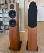
Toroidal core calculation

Hi

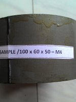
Few days ago I got sample of toroidal core from my friend. I don't know any technical details of core just know OD-10cm, ID-6cm, height- 5cm and wet about 1.845 kg(M4 grade). I want to make toroidal transformer using this core but how to calculate core area and maximum VA capacity of core.I take some photos and attach.
please help me.

Attachments

  • P_20160615_154250.jpg
    P_20160615_154250.jpg
    466.6 KB · Views: 786
  • P_20160615_154347.jpg
    P_20160615_154347.jpg
    503.4 KB · Views: 699

No I did not!

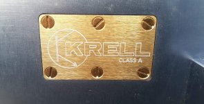
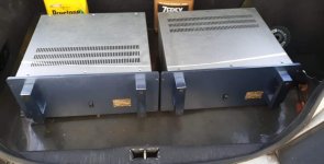
Yes I did .., could not resist getting these babies, Krell KMA-100 .., they do need an overhaul .., the boards are in good shape

Any information, specs sheet, user manual, schematics, Krell advertisement, test report, owner experience .., would be highly appreciated

Attachments

  • received_380040756325354.jpeg
    received_380040756325354.jpeg
    98.9 KB · Views: 294
  • received_2364649113844712.jpeg
    received_2364649113844712.jpeg
    51.1 KB · Views: 294
  • received_780917622676058.jpg
    received_780917622676058.jpg
    654.2 KB · Views: 298
  • received_602617867080217.jpeg
    received_602617867080217.jpeg
    576.5 KB · Views: 299

Correct wiring of an MC step-up transformer

This is a general question. I built a pair of step-up transformers in a metal box. The input and output RCA sockets are mounted isolated from the box. I connected the L channel RCA input GND to the output GND, similarly the R channel RCA input GND to the output GND. Then I connected both transformers' shield to a GND screw on the metal box. So the L channel GND is isolated from the R channel GND, and both are isolated from the metal box.

My turntable has a built-in RCA cable and a separate GND cable that is connected to the chassis of the TT. If I leave this GND cable unconnected, there is big hum. I connected this GND cable to the GND screw on the MC transformers' metal box, but there is still some hum. The hum is much reduced if I tie the GND screw to either the L or R channel RCA connector's GND.

I wonder if this is the correct way of GND connection? Where is the turntable chassis GND normally connected to (if there is an MC step-up transformer between the cartridge and the phono preamplifier)?

Symasym 5.3 "AAK model" builder's thread

Welcome! This thread is for all those who bought the PCB for Mike Bittner's Symasym 5.3, this PCB model designed and tested by "AAK", and organized / produced by "Ryssen". AAK's design implements several incremental changes, most notably very linear Toshiba output transistors (and drivers), a change also rcommended by Pavel Macura (PMA), and 50V rails instead of 36V. All this is done in a compact PCB design of 5x3", intended to mount on top of a 4x5" heatsink.

It is for all discussion related to the actual building process: BOM, components, modifications, testing, functionality, and eventually, one might hope, sound quality 😀

Related threads and posts:

PCB group buy , with all PCB related complementary info in the first post of the thread. This round of the GB is closed, but another round may be forthcoming if interest keeps coming in strong.

AAK's design

Mike Bittner's original design

Pavel Macura's review and technical recommendations

I'm new at this. Is this a good measurement?

Hello.
I'm trying to measure a DIY headphone driver in a pair of headphones I made and I'm a total noob at this measurement stuff so I'm looking for guidance and outside interpretation.
Not sure if my settings are correct but here it is.

zL7sy5H.png

vfzD1jN.png

GXcOZo7.png

F0H0lLE.png


linear waterfall plot

D6D1Ncq.png


For some reason the log waterfall plot didn't display under 200hz unless I expanded the window to 60ms

9BcU0tw.png


Do my settings look alright?
Also what's the deal with all the valleys in the waterfall response? Is that really the driver decay?
And is there a method for smoothing out all those wrinkles in the FR?
Are those wrinkles audible? Is there something in this mess of data that I should focus on improving?

Life in the time of the Virus

It seems now most of Europe, US, Australia and Asia is now in the grip of the most infectious virus the world has seen since the 1918 Spanish Flu.
All non-essential businesses, and even Schools and Universities, are about to shut down in Victoria, if not most of Australia. This will have a profound effect on small businesses, family life, and particularly on social life for all of us. 😱

With a number of underlying health issues, my wife and I are in the zone and need to be very careful. No parties, no personal contact with friends and family, and minimised association with other people in any situation.

This is a moment in our lives where we need to remain calm and learn to spend our time in solitude, hopefully doing something useful like reading a terrific book, learning something of the world in a documentary, enjoy music, or - dare I say it - build something of beauty like an Aspen Amplifier!!

In the last eight years since my AAA nearly took me out, I have produced one after another of new designs. We have the latest version of the Maya, the SAKSA, the open source ALPHA and ALPHA Nirvana published by XRK971 in the SS forum. This last amp is a rare design from me; it is a Class A of quite unusual high efficiency (43%) and it does 39W into 8R. The sound quality of this amp is peerless, up there with my Maya.

I would like to offer my best wishes to all Aspen customers from past, present and future; and suggest that we will all get through it. It's serious, but with intense quarantine and isolation we will flatten the J curve and quickly contain the contagion.

And finally - buy an Aspen module, and put it in a box for your wonderful enjoyment through the next six months! 😀

Ciao,

Hugh

quick inwall/onwall project

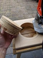
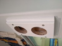
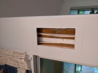
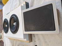
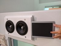
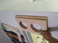
Recycling parts from my old open baffle surround channels for the new house setup which requires surrounds to be up off the floor and mounted. Decided I had just enough room either side of the sofa to make some sort of in/on wall hybrid. The outside wall column has less depth available than the inside column, so I had to get creative and make the baffle extra thick to accommodate the depth of the Ascendant Audio Poly 6.5. Ended up with 4 layers of 1/2" cheap plywood glued up and coated with Duratex. First time using it and I'm impressed! Goes on smoothly and bumps up to a nice, consistent texture using the supplied roller.

I purchased a set of NXT desktop speakers off of Ebay out of curiosity and had hoped that they'd be suitable as a mid/high driver. They look nice and would have complimented the design better, but the old Neo8 easily beats them for smoother response and lower distortion, so I've got to figure out a mounting method. I'm thinking I might open the NXT to rip out the guts of the panel and there should be enough room to fit the Neo8 inside.

My entire system is active, mains running on Hypex Fusion 3 way dsp/amps. The surrounds will be bi-amped with the old Behringer DCX2496 and an Outlaw Audio amplifier.

Attachments

  • baffle cutout.jpg
    baffle cutout.jpg
    310.5 KB · Views: 124
  • baffle test.jpg
    baffle test.jpg
    171.2 KB · Views: 132
  • baffle on wall.jpg
    baffle on wall.jpg
    184.7 KB · Views: 127
  • hole in wall.jpg
    hole in wall.jpg
    194.5 KB · Views: 124
  • baffle with NXT.jpg
    baffle with NXT.jpg
    376.2 KB · Views: 124
  • baffle with Neo8.jpg
    baffle with Neo8.jpg
    309 KB · Views: 73
  • baffle complete.jpg
    baffle complete.jpg
    207.1 KB · Views: 82

Using the Dayton PC105

AFAIK, Wolf Teeth is the only member who has used these drivers before, despite them being efficient & cheap, with a pleasing looking wide flattish frequency response marred only by a small peak at ~8.5KHz. https://www.parts-express.com/pedocs/specs/295-158--dayton-audio-pc105-4-specifications.pdf

Having recently tried a couple of WAW style builds, but being disappointed by the lack of dynamics of the Dayton PS95 and Vifa TG9 (They’re too inefficient), I decided to try a conventional 3 way using the PC105, paired with a Dayton ND20 tweeter (Foolishly I chose the rear-mount version, front mounting would have been so much easier). I used a Wavecor WF138 woofer I had available, because I knew it would work well in the re-purposed 20L test boxes.

I kept the crossover minimal, 1st order electrical on the woofer & mid, and 2nd order on the tweeter, rewinding inductors from my junk box to get the required values. No resistors required! - the sensitivities matched very well. Crossover frequencies are 540Hz (Baffle step) and 5Khz.

The sound is detailed and dynamic, as expected, with drums and guitar coming across particularly well. The Wavecor woofer does the low end very well to match, (although, naturally, I preferred the sound with my 10” Peerless woofers switched in as well). The HF peak wasn’t audible, to me at least. Maybe I’m showing my age...

Unfortunately the Wavecor woofer is NLA, so I will at some stage be doing a rebuild of these using a pair of SB 13PFC woofers, which work in the same sized box. One of my goals with recent builds has been to keep the box size to ~20L or under.

Attachments

  • Pc105a.jpg
    Pc105a.jpg
    3.7 KB · Views: 305

8600 Desoldering Woopsie

Hi all,

I am currently upgrading the resistors to Takmans on my 8600.

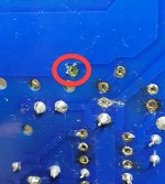
All went well until I got to Resistor R240. The desolder tape got soldered to the pad and ended up taking the pad with it - see pic attached. 🙁

I guess my options are:
1. nuke option: Negotiate for a replacement board from Elekit
2. Hope that with enough solder, it will make contact with what remains of the sides of pad.
3. Add appropriate jumper wires to connected components.

Anyone have any suggestions as to the best course of action?

I really like my 8600, so I'm quite angsty about this.

Attachments

  • R240Woopsie.jpg
    R240Woopsie.jpg
    365.2 KB · Views: 222

Which amplifier for this big capacitor?

Hi.I have high stock of these capacitors.They are one of the best quality capacitors ever made but because of the voltage and capacity there is not much usage of them.I heard they are made by special expensive technique.
Anybody recommends good quality sounded amplifier schematic by using these 3300uF 250v Type GH F&T Germany made caps?I do not want to send them to trash bin.Thanks

Attachments

  • ft3300uf250v.jpg
    ft3300uf250v.jpg
    170.6 KB · Views: 417

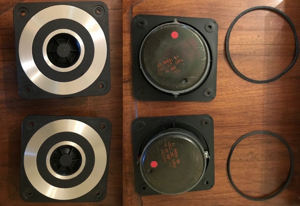
a (cheap) small (waf) build 3-way (made from salvage)

a (cheap) small (waf) build 3-way (made from salvage)... 😕

It's a first step for a possible much larger project to come. 🙄

Click on the pics to see the correctly sized version 😉

The project - on paper :

GcefKb-projet-WAF-3W.jpg


The boxes - recut 18mm pinewood planks :

uZdfKb-boxes.jpg


The speakers - all from re-use :

NZdfKb-speakers.jpg

8iBfKb-my-PHILIPS-tweeters-AD01631T8.jpg


The midrange back covers - PP tupppz or PVC pipe - will end to be the PVC version (a bit larger) since the lead disk are not glueing satisfactorily on PP :

FZdfKb-back-covers.jpg


Finish : two-tone Tolex covering (like a guitar amp)

Wait and See... 🙂
A+!

FS: SonnyA's discrete preamp with chassis, OLED & his PSU

I have one of Sonny's SITO discrete gain modules based preamps going spare, already in a black chassis (see attached) and including his LPS v2.1 PSU.

This can be controlled by the Apple Remote (included).

There is space in the chassis to also install his USB DAC module at a later point.

(will attach an IEC socket before it leaves)

£400 ono + p&p, can ship to UK or europe, will consider to USA too.

Attachments

  • internals sonny discrete pre.jpg
    internals sonny discrete pre.jpg
    475.6 KB · Views: 294
  • IMG_20200430_140019 (1).jpg
    IMG_20200430_140019 (1).jpg
    275.3 KB · Views: 290

ACA v1.8

Hi,

I am new to this forum and I write from Spain.
I just bought two units of ACA v1.8 (I am eager to build it when I receive it) and I am reading a lot in this forum, but ACA v1.6 threads are very long and dense.
I have a question that may have already been answered. I hope you forgive me.
From what I see, the best operation is in two monoblocks in parallel input since the specifications are from 16w to 4ohm, 8w to 8 ohm and a damping factor of 20. Is this correct?
My question is how the speakers are connected to the amplifier, since I am looking at the connection diagram on the rear panel and I did not quite understand it very well. Could someone clarify for me?
On the other hand, I understand that in this mode of operation it is not necessary to connect the two RCA (L / R) since the connection is internal. Right?

Greetings from Spain

PS: sorry for my English ...

Best, easy, powered 3 way speaker plans?

Hi, I’m looking to build some speakers for my garage. I’m looking for:

- Easy to build (I’m ok with making an enclosure, but prefer minimal fussing with interior chambers. I’m comfortable cutting wood, using silicone and wood glue, nothing too exotic like the shaped designs some folks do)
- 3 way, two boxes
- 10” drivers or smaller (I’m cross shopping this idea against the JBL Eon 610)
- Really high driver quality
- I think I want a crossover. I don’t like the idea of the woofer playing my highs or vice versa.
- Bonus points for powered so I can just hook up my iPhone to it. Probably will want knobs to control the sound.
- Bonus points for the ability to put a metal grille on it.
- I can drop the powered requirement if needed.
- Bonus points for a relatively larger driver in a relatively compact enclosure.

Cost under 750 ideally. I prefer to make my own cabinet.

Accurian Homeplug System

Good Morning,

About six months ago I purchased an Accurian Homeplug speaker system off Craigslist. When I brought them home, I set them up, connected them to my Wii and they worked beautifully. The next day none of the speakers would play, though all definitely had power. I suspect the audio injector to be the problem, but have no idea what steps I can use to troubleshoot the problem. I set them up again yesterday and hooked them up to my Mac, again, they worked beautifully, this morning, nada. I happened upon your forum looking for a solution and have a feeling that if there is an answer to be had; it's going to come from a member here.

Thanks you
Gary

Resistor Equipped (RETs) / Digital / Pre Biased Transistors testing?

Hi


I think I may have miss-diagnosed two transistors in a CD/MD player and could do with some advice.


I read the service manual, read about the problem, which board the fault could be on and also the area of the board that could need attention.


I found 1 electrolytic that was WAY out of spec and replaced it, like for like.


I also found 2 transistors that didn't test as working at all. Wondering if it was because they were still in circuit I pulled them out and tested again. Same result. I decided to look up the data on the 2. When I started reading I noticed that they were pre biased transistors. I tested for resistance across two of the legs that meant the two resistors inside the package would be measured in series, these values 10kΩ on Base, 47kΩ between Base and Emitter seemed to add up. Though I still couldn't test the transistors normally, the way I would to identify NPN/PNP, Base, Emitter and Collector (which I now know after reading the data sheet).


I do apologise if I am missing something obvious that I should already know but I have already done a lot of searching from searching several books, youtube and good old google etc and Ive not found anything that makes sense to me regarding how to test such transistors out of circuit.


The Transistors in question are KRC107M, which seem to be hard to find or disproportionately expensive.


Any advice much appreciated.

Conn organ conversion to amp

Schematic needed for a Conn UA 6026 organ chassis - do not have any other information on this unit, but I just could not pass it up - it has tube positions for 4/7027A, 2/7868, 2/7199, and 2/12AX7 - just the 7199 & 12AX7 are missing. Everything else appears (cosmetically) good.

I did not get a chance to look under the hood, but I think it has potential as an audio amp or guitar amp. Does anyone have any information on converting an organ amplifier to audio or guitar use?

Thanks for any help.

nuvo😀

DIY Active Subwoofer Help !!

as usual whenever i need help im here
im trying to make active subwoofer im using 8" woofers in which i dont know any specs a bout it was a lot at good price and i bought them .
first i made Rod elliot 24 dB/Octave crossover "project 09"
Linkwitz-Riley Electronic Crossover
and used both TDA 7294 amp and STK 4191V amp
the problem is i cant get a clear good bass i don't know how to describe the sound but whenever the volume is down the bass is so clear and good but turning volume high i began to hear distortion and after changing the cabinet and port i got no distortion but bass not clear even f i replaced the woofer with another kenwood one it doesn't matter
i referred to some old jbl and jamo schematics and found they are adding a high pass filter "Subsonic filter" i did so with no much difference .
i've tried other crossover circuits with no noticeable difference
the only weird thing for me is when i tried that crossover on a 12" driver in sealed enclosure i got magnificent bass shaking really shaking my room with a great quality.
am i missing anything....i need help i have been for 2 months on that building different enclosures with different tuning and different crossovers and amps i got tired and almost frustrated😕😕 !!!

Overengineering in audio equipment

Hi ! sorry for being the guy with the weird questions ... but there is this KISS principle always buzzing in my brain.
Is Overengineering a widespread practice in audio designs ? 😱
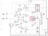
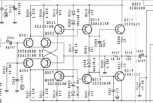
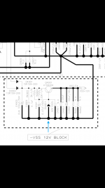
Just to talk about one case ... i am attaching the schematic of the gain stage of a line preamp
Why not to limit the circuit to the first push pull on the left maybe replacing the Q511-Q509 pair with the Q517-QQ519 pair and move the ouput stage to the left and in this way save 4 bjts ?
I am sure it could provide very similar electric performance in terms of distortion. Maybe the circuit would have lower PSRR ?
Would not be elegant a simpler schematic providing very similar (if not even better) performance (with the right selection of parts of course)
Let's remember we are talking about a line stage ... very small voltage gain needed and good driving ability (and with coupling cap at the output)
Thank you very much indeed.
Kind regards, gino

Attachments

  • rotel gain stage.JPG
    rotel gain stage.JPG
    74.1 KB · Views: 1,125

What's your dynamic and quiescent power supply loading?

If you think about it, most power supplies expect to provide some DC current continuously. Particularly switchers. Not that a PSU cant be designed to behave well through zero current load; there's many lab grade benchtop units that can do this...

Consider an H bridge driven to make a sine wave into a resistive load, from the perspective of the powersupply. The bridge tips positive and current flows - from nearly zero - following the lobe of the 1st cycle half. Then the bridge tips negative and a similar current flows; the current for a complete cycle looks like rectified DC - two sequential positive going lobes, that touch zero - or darn close to it.

Consider a class A amp. That "cooks" the output devices with lots of current and voltage drop, while the output node moves up and down within the constant current flow; the "quiescent" current burn being much more than that delivered to the speaker. So the powersupply sees - essentially - a constant current load. At least a lot moreso than with the H bridge.

When we consider the sound resolution of very faint levels, we can see the class A is delivering such with a good chunk of constant current load on the powersupply, while other amplifiers... It would certainly be an easy experiment to do; add some DC load to your power supply and see if it sounds better. Class A, of course, not necessary!

Consider a woofer flapping about it's full Xmax - than directed to stop suddenly by the amplifier. Damping factor is one way to describe what that woofer "sees" electrically, looking back into the amplifier output, whose character gives it something to electrically "push against". Where does the emf go, as the output devices conduct the speaker current "somewhere"? Does this not reduce any small bias current the powersupply is providing even more toward zero? Perhaps another reason to preload your powersupply.

A couple of reasonable considerations - never mind any wooey-hooey about electrons preferring to flow continuously one way - or not having to stop.

Where's your powersupply operating when within that first watt?

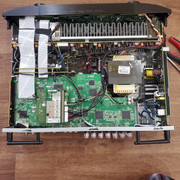
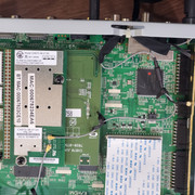
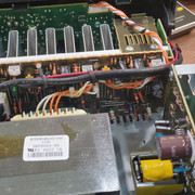
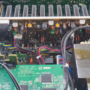
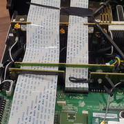
Marantz NR1605 clicks on then goes right back off

Hi all.

So I bought a Marantz NR1605 A/V off of eBay "as-is". The description reads:

Marantz NR1605 AV Receiver As Is, no returns or guarantees Shipped with USPS Parcel Select Ground. This was a new receiver purchased in approximately early 2015. The receiver still turns on but I think during a power outage/surge something happened to the HDMI in/out capabilities. The receiver is included with the adapter, manual, and remote control

They are correct - it does come on but only for a few milliseconds before turning off. I bought it thinking that it probably would just be a blown fuse or something I could see a burnt component on the board that I could replace.

Opening it up I found a total of 4 fuses. Each fuse looked just fine. Nothing blown. Examining the board(s) inside they all seem clean and shinny/new looking. Nothing on the board(s) look burnt or leaking in any way.

However, I am unable to figure out what the steps are in order to take each PCB board out in order to see what beneath it - if there are any more fuses or check for something burnt/leak.

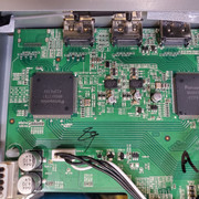
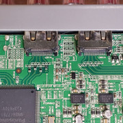
I have taken a good amount of pictures in order to let you see what I am seeing. Perhaps you would be able to spot something that I have not. Or better yet, let me know how to go about taking the PCB boards out. I also have 2 videos showing it [URL="https://www.dropbox.com/s/yjb98avhwpsrfwz/20200815_141224%20%281%29.mp4?dl=0"]coming on and then off[/URL] and also what it looks like on the LED screen when it comes on.

ALL Images here


replacing one 8ohm sub with two 4ohm

I recently blew my 18" sub and am looking to replace it. I was coming up with a rather waffly question and decided to cook it down a little instead.
I have an EPQ2000 amp(2 x 1000 - 4ohm or 1 x 2000 8ohm)
Should I replace the old sub with:
Option A - Fane Colossus 18XB 8 ohm(99db)
Option B - 2 x Fane Colossus 18XB 4 ohm(99db) (double the budget but double the fun?)
or Option C - Fane Colossus Prime 18XB 8 ohm(100db) (25% more than option A but i get an extra db)

Cheers

Exposure VI/VII high pitch 'whine' problem.

Just finally 'finished' an Exposure VI/VII combo that I've 'restored' from a rotten/non-working state.

  1. Removed all Tant. beads, and replaced with correct electrolytics.
  2. Updated remaining small electrolytics.
  3. Tested VI (PSU), and made up 2 x 5pin Domino/Dice Din leads to connect to VII Pre...all tested good (to me!)
  4. Powering on...Line inputs all present, but Disc (MM) input was initially intermittent (LH)...then LH stopped, leaving only RH.
  5. After a few minutes....high pitch audio tone can be heard on LH....regardless of input selection.


Now, I have to remove both boards to get down to LH Channel board🙁
Suppose I should've tested each board before building back into casing...DOH!!
I'll check my soldering, and look for any dry joints....but would appreciate any other ideas/pointers please!!

Seeking advice on NAD 502 display bulb repair.

I'm about to replace the burned out incandescent bulbs with LED's. I've read various articles on the subject, here and elsewhere. My question is this...I've read that the two bulbs are wired in PARALLEL, but it's suggested to replace them with two wide angle LED's wired in SERIES with a resistor on the anode of the "first" LED. Good so far? I've also read that the bulbs were powered with -15v rather than +15v, so the arrangement of resistor/led/led would be installed backwards, correct? That doesn't change where the resistor is mounted, does it? Thanks!
BTW, I received the player with the issue that the door wouldn't stay closed. It would close and then reopen, so it wouldn't play a disc. I boiled the tray drive belt in water for about 15 minutes and now it opens and closes and plays perfectly! I will be ordering a new belt anyway.

Accurian Sender Repair help 15-1938

I recently received this accurian wireless sender (15-1938) and accurian wireless speakers. The sender does not power on and I believe (hope) this should be a relatively simple fix. I traced the circuit board via the images with my volt meter and lose power on the output side, of what I am calling, the power transformer. I was hoping someone here could look at the high-res images I have linked below and give me some suggestions on repair. I am a laymen and that might be pushing it a little...
I look forward to some suggestions

Here are the images:

Botttom: http://i298.photobucket.com/albums/mm247/junknstuff_photos/15-1938003.jpg

Top:
http://i298.photobucket.com/albums/mm247/junknstuff_photos/15-1938001-1.jpg

Thanks

3-way active crossover, opamp instability on power loss

I'm just looking for a little advice here.

I've built a stereo 3-way active crossover following the Elliott Sound Design schematic and using a pair of Salas SSLV 1.3s to provide the +/- 15v for the boards however I'm facing a -3v surge on power off as the op-amp voltage drops.

My thoughts are to use a few relays to switch the output off on power loss, but I was also thinking perhaps there's a way to even the voltage drop so the op-amps (LM4562) behave 'properly'.

Thoughts?

test equipment for diy tube amplifiers

I can't decide between Analog Discovery 2 and external soundcard + software for diy tube amplifier testing (THD+N, IMD, frequency response etc.). On one hand sound interface is 4x cheaper, on the other, AD2 seems more functional and more accurate test equipment.

Or should I save money for something more serious? Like HP 3561A or 3562A Dynamic Signal Analyzer.

As always I really appreciate your thoughts guys. Thanks!

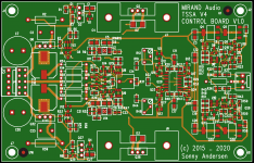
Mirand TSSA V4 and V8 Lateral mosfet amp

TSSA V4 and V8 buyers thread.

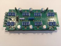
After a lot work around on the TSSA V4 control panel, the frontend is now ordered and we will receive the frontends end next week.

The front and powerboard is the same. The difference between the TSSA V4 and V8 is only the mosfets.

On the TSSA V8 the current capacity is the double of the TSSA V4. In numbers 63Apeak against 39Apeak. TSSA V8 will also have a bit higher damping factor.

Both amps can now handle +/-75VDC power supply as well as down to ~+/-30VDC. But because of the current capacity the V4 is best for 4 - 8Ohm speaker where the TSSA V8 can handle down to 2Ohm.

The best minimum idle current for TSSA V4 and V8 is 400mA and 800mA. For this reason TSSA V8 requires a larger heatsink.

Some have asked for use of hypex 1200/400 SMPS with this SMPS idle power consumption will at minimum bias for the TSSA V4 be 50W/channel and for the TSSA V8 be 100Watt per channel.

So the heatsink recommendation for using Hypex 1200/400 is:

TSSA V4 <0.6K/W per channel
TSSA V8 <0.3K/W per channel

The prices on the amplifier modules are

TSSA V4 will cost 314€/per channel. + shipping

TSSA V8 will cost 449€/per channel. + shipping

From 4 channel and up there is an discount of 30€ per channel

The early bird price which runs until the 12. june is.

TSSA V4 will cost 254€/per channel. + shipping

TSSA V8 will cost 389€/per channel. + shipping

And again there is an discount of 30€ per channel at 4 or more channels.

Attachments

  • tssa V4 control board V1.0.png
    tssa V4 control board V1.0.png
    160 KB · Views: 2,409
  • IMG_1542.JPG
    IMG_1542.JPG
    626 KB · Views: 2,391

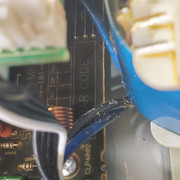
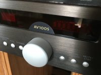
Thule AV100S with whistle tone

I am trying to find out what is wrong with a Thule amp. It gives a constant whistle tone of about 4kHz. Independent of volume or input selection. In both channels equally.
Anyone with an idea of the problem? Maybe it is interference of two high frequency signals from the clock?
Or display?
Another question: can someone find the technical reference or schematics of this amplifier?
Many thanks in advance.

Attachments

  • E46B6EA6-385C-4386-A14E-6EEA3F1E6FA8.jpeg
    E46B6EA6-385C-4386-A14E-6EEA3F1E6FA8.jpeg
    73.2 KB · Views: 54
Projects by fanatics, for fanatics
Get answers and advice for everyone wanting to learn the art of audio.
Join the Community
507,844
Members
7,890,438
Messages

Filter

Forum Statistics

Threads
406,357
Messages
7,890,438
Members
507,844
Latest member
Amirbutt