BSS FCS-926 Parametric EQ - Butchered PCB...

Hello,

Just got a FCS-926 Equaliser, I've been looking for one for some time, it has analogue filters which are digitally controlled..
Info about the unit here: FCS-926 | BSS Networked Audio Systems

Unit arrived with multiple marks and was quite dirty so I thought I'd clean it quickly before installing it.
As soon as I opened it I noticed these awful modifications as if someone 'serviced' it with a kitchen knife, it's absolutely butchered.. 🙁

Can someone trace the changes and help me understand what has been done?

Back panel MIDI connectors:
attachment.php


Real Time Analyzer:
attachment.php


attachment.php


attachment.php


Front panel ribbon connector:
attachment.php


R92 disconnected:
attachment.php


Cheers!

Attachments

  • 20201221_222844m.jpg
    20201221_222844m.jpg
    940.9 KB · Views: 677
  • 20201221_222913m.jpg
    20201221_222913m.jpg
    939.7 KB · Views: 581
  • 20201221_225206 (Custom).jpg
    20201221_225206 (Custom).jpg
    942.3 KB · Views: 562
  • 20201221_225235_HDR (Custom).jpg
    20201221_225235_HDR (Custom).jpg
    731.3 KB · Views: 599
  • 20201221_222921m.jpg
    20201221_222921m.jpg
    923.1 KB · Views: 569
  • 20201221_225249 (Custom).jpg
    20201221_225249 (Custom).jpg
    623.7 KB · Views: 579

Power supply elimination

I'm planning to clone a commercial preamplifier; Nakamichi 410. Since I'm new to electronics, I'm wondering that if the equipment needs +10V and -10V for operation, can I substitute the power supply section shown on attached by a switching or any +/-10VDC supply circuits? In brief, can I eliminate the attached circuit by substituting a ready-made power supply unit?

Attachments

  • 135754984_759254111348656_1731291751091661537_n.jpg
    135754984_759254111348656_1731291751091661537_n.jpg
    59.1 KB · Views: 134

using a Raspberry Pi 4 as a USB DSP-DAC

I have been using the Raspberry Pi platform for several years to implement DSP (via LADSPA plugins) and as streaming clients in a whole-house audio system based on Gstreamer. In this scenario, there is a "source" computer that is playing some audio stream, the stream is directed over my LAN to another Linux computer (e.g. the Pi), and then the audio is split up in to multiple channels, DSP is performed on each channel, and then it is rendered via a DAC.

I recently rediscovered the "USB Gadget" module that has been around for a few years. This uses a USB OTG host to act as one of a number of different kinds of peripherals. The way it works (as far as I understand it) is that you configure the USB OTG host to signal that it is a device of the kind of your choosing. When you connect the gadget device to another USB device, it appears as that kind of peripheral. Adafruit has a very nice tutorial about this here:
Overview | Turning your Raspberry PI Zero into a USB Gadget | Adafruit Learning System
The Adafruit tutorial is written for a Pi Zero. The Pi Zero is not really up to the task of doing DSP unless it is very basic stuff for one or two channels, however, it does show the necessary steps. Note that one of the possibilities is to create an "ethernet gadget".

It turns out that the new Raspberry Pi 4B also has an OTG capabilities via the USB-C port (typically used to provide power to the Pi). We can use this OTG host to convert the USB-C port into a USB gadget connection as long as we power the Pi via other means (e.g. via the GPIO pins).

As luck would have it, I have been using an 8-channel HDMI audio extractor HAT that can power the Pi via the GPIO pins and can provide 8 analog outputs at up to 24/192. When combined with the Pi 4 running as a USB gadget, the Pi can receive audio, perform DSP on it, and then output up to 8 independent channels. This would comprise a very nice USB DSP+DAC unit!

So, how do we set this up?

The way I plan to do it is to put the Pi into "ethernet gadget" mode. Then, when the Pi is connected to another computer via its USB-C connector, it will appear as an ethernet connection (see the Adafruit tutorial at the link above). It is then a matter of redirecting the Windows audio output over this USB ethernet connection, receiving it on the Pi, and so on.


UPDATE: SEPT 3 2019:

The script files and HOW-TO for setting up and streaming audio in this way are attached to POST #77 of this thread. This is version 1.0 for all of these documents.


last Edit: 3 SEPT 2019.

SBC with I2S codec drivers for playing/recording

Most SBCs can be used in conjuction with a cape or plugin module supporting an I2S DAC to play sound.
Usually these SBC support a Linux distribution that includes ALSA drivers, over which one can add Jack, Pulseaudio and support other high level applications for playing music.
What does not seem to be so obvious is to find I2S ADC recording support.
Some time ago I thought I could use a Odroid C2 which is quite compact in size and includes a quite powerful quad ARM. I could even develop myself the HW including a I2S codec board. Unfortunately the Linux distributions do not support I2S recording drivers for Amlogic processor, and it's impossible to get support to make a driver for yourself.
So far I haven't been able to identify a SBC that is able to support play and record/capture MMAP drivers using I2S ADC/DAC codecs.
I find hard to believe that audio recording is not supported by SBCs in the market.
Does anybody know of SBCs that support this?

Tektronix 475 HV Circuit repair

Old pieces of test equipment from brands like Tektronix, HP etc. are still used today by many people due to their really high quality. However, many times, when they are in need of repair, spare parts prove to be quite difficult to find, especially in reasonable prices. I found myself in this situation around two and a half years ago (July 2018) when my trusty Tek 475 oscilloscope presented a fault in its high voltage power supply.

This scope has presented some other faults in the past. Its CRT was replaced in 2017, after being broken, during shipping. Also, the high voltage multiplier was replaced in June 2018. After that, a slight hissing noise could be heard, when turning the scope on (something was arcing inside the high voltage box). The noise, however, would stop after a while (5 – 10 seconds), and the scope would work normally, so I did not do anything about it. One or two weeks later, this noise became continuous and the display stopped functioning. I opened the scope and removed the vertical preamp board and the HV cover (as described in the service manual) only to find a faulty HV transformer (the secondary winding measured open between the tap providing the cathode bias and the end going to the HV multiplier to provide voltage for the post deflection anode).

From this link you can download the service manual:
475 Instruction Manual | Tektronix

The high voltage circuit schematic is on page 220.

Attachments

  • Front.JPG
    Front.JPG
    606.6 KB · Views: 285
  • Crt and vertical output amp.JPG
    Crt and vertical output amp.JPG
    697.1 KB · Views: 289
  • Main board.JPG
    Main board.JPG
    682.6 KB · Views: 232
  • Vert preamp board.JPG
    Vert preamp board.JPG
    657.5 KB · Views: 340
  • Trigger board.JPG
    Trigger board.JPG
    666.8 KB · Views: 257
  • Faulty transformer  inside HV compartment.jpg
    Faulty transformer inside HV compartment.jpg
    758.9 KB · Views: 258
  • Faulty hv transformer (1).jpg
    Faulty hv transformer (1).jpg
    450.5 KB · Views: 233
  • Faulty hv transformer (2).jpg
    Faulty hv transformer (2).jpg
    828.1 KB · Views: 267
  • secondary open.jpg
    secondary open.jpg
    672.1 KB · Views: 246
  • 120-0815-00 x-former data.JPG
    120-0815-00 x-former data.JPG
    120.7 KB · Views: 287

Rotel RA-980BX

Hi,

I am having a problem with this amp. This amp does not have a balance pot but individual volume pots. The problem is the right channel is much softer than the left. If I set the left channel level at quarter, I have to set the right channel level at more than half to make it sound balanced. I checked the volume pot (50KA X 2) and it is OK. I removed the 2 links between "pre out" and "main in" and plug a signal into the 'left main in" and 'right main in' and the left sound louder than the right. I guess it means that it has nothing to do with the "pre out". I checked all the components on both the power amp boards, all seem to be OK except that resistor R669(10 ohms, 3 watts) has blown, but this resistor is on the left channel which is working OK. I am confused. Can this resistor be the problem. Please help.

Thanks

Carlos

1975 Fender Princeton Reverb (no sound)

My son picked up a 1975 Fender Princeton Reverb Silverface at an auction.

It was pretty dirty/rusty, but when we plugged in it, it worked...briefly.

Now, though the pilot lite works, there is absolutely no sound, no hum, no nothing.

Is this a symptom of a bad transformer? They are really rusty.

I checked all the tubes (with a tube tester) and they appear to be good, and they glow when in the amp and powered up.

I used deoxit on all of the pots and tube sockets, as well as tried other speakers

Any advice on where I can begin troubleshooting?

Alpair 10p Build

After much thought and consideration i have decided to go ahead with the Alpair 10p.

I really want to do something like this:

TLb -- Table of Contents

Run a couple per side in a transmission line bipole. Should i run the rear one full or throw an inductor on it? I assume the size of the inductor will be relative to the size of the baffle? How does one calculate this in a bipole configuration?

Thoughts on this design?

Thank you!

  • Locked
simple hacks for high end audio

this list of hacks isn't elitist, it can work with mp3 too.

1. use a computer, and it's not only because you can play dvd-a or dts-hd ma or good rips with foobar, which has very low distortion compared to an average 1.4Mbps flac, and also richer and detailed sound, mostly at higher volumes. With a pc and a decent soundblaster with low snr you can have good sound, NEVER use USB or external DAC since the levels of tweaking and preamplification inside the computer is lost when sending the sound data via USB to a dac, preamp or amp (see next).

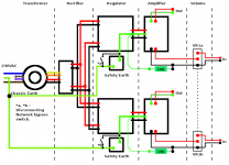
2. (edited, I didn't explained well) Gain structure or stages of preamplification and volume levels between player, windows, preamp, amp. This is the most important step, keeping this setup: amplifier volume as maximum as possible (this is only the volume you have to tweak along with Foobar's volume)> preamplifier at max volume> windows at max volume > foobar at lowest as possible (with mp3 you can have good sound keeping at bare minimum, with 1.4Mbps Flac you can raise foobar volume and with dvd-audio you can raise even further foobar's volume without distortion). This is the only way to listen the best sound, with more richness and less distortion but you can easily destroy the speakers with a sudden sound in the computer. The tune is between the humming noise-audio richness of amplifier volume and distortion in Foobar volume , also with higher volume you don't notice humming noise so you can keep amplifier at maximum having richer sound, also dvd-a has richer sound when increasing foobar volume since at low foobar volume dvd-a has good undistorted sound but with little sound body. Also you can tweak windows master volume with equalizerAPO and Peace. Also 31 band parametric EQ with foobar is the best way to tune the sound.

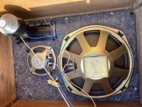
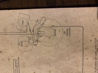
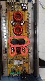
3. removing crossovers, this removes energy consumption, increase spl and give you great levels of sound tweaking. With a 5.1 soundcard you can have well tweaked active stereo speakers (with 5 channel foobar EQ) and have 2 channels for mid-highs, 2 for bass-mids and .1 for subwoofer. Also you can use 2 channel EQ board (acts as a preamp and you have more sound tweak) and class d boards which are very energy efficient. With all the setup posted above, you can use a 50W board and deliver very loud homewrecking sound, and that's because the sound has been amplified to the max before arriving to the amplifier and are very efficient.

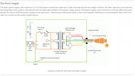
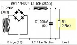
4. cutting AC. Most of the noise comes from AC, if you hook all the stuff to a battery with solar panels you wont have that humming noise that appears when you use the above settings.

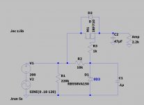
5. no wires. a way to totally remove wire SNR is using sound via Bluetooth with arduinos and lossless Bluetooth boards, with each speaker with a class d board attached and Bluetooth board.
akrales_171011_2046_0152.0.jpg


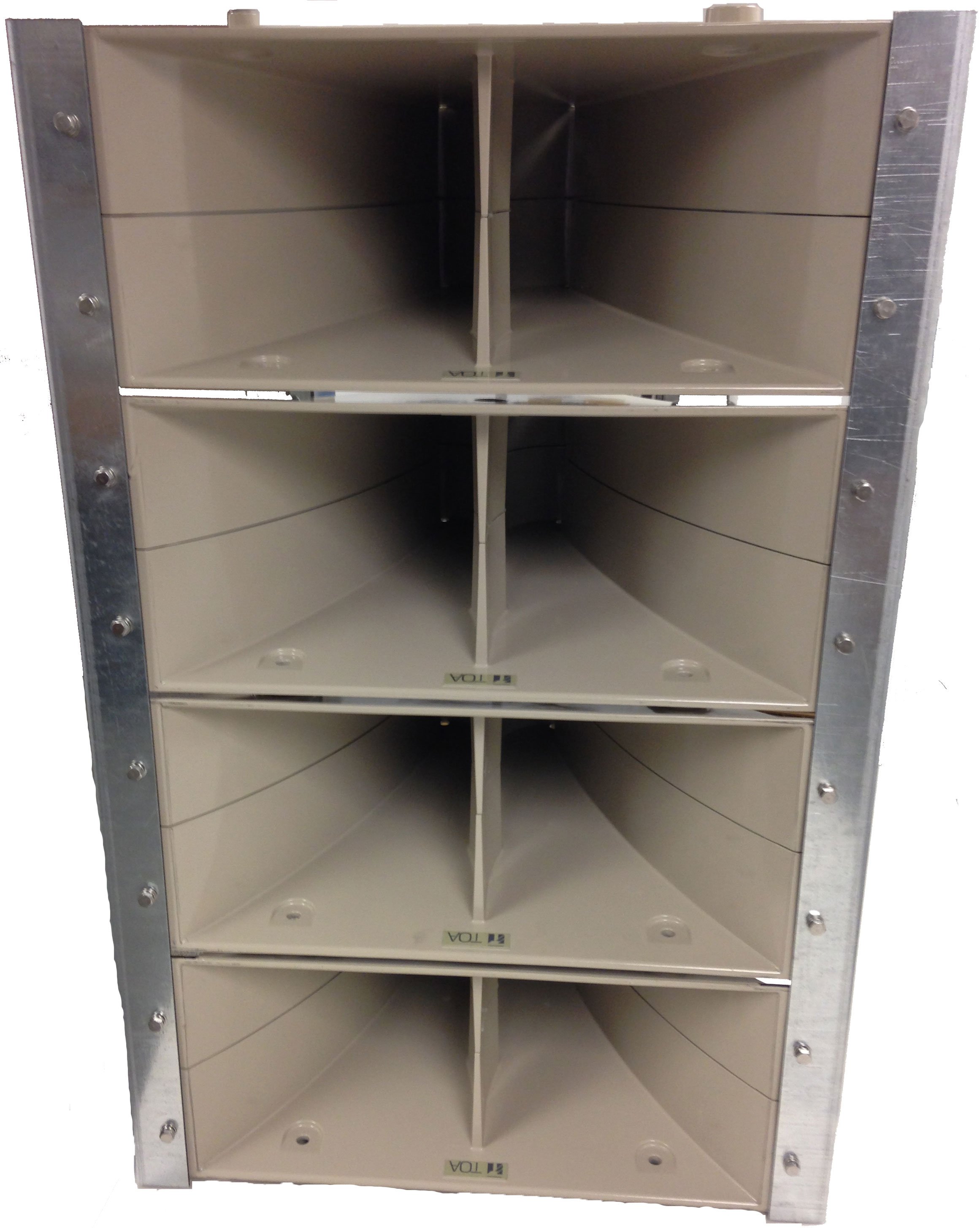
6. arrays or horns is the only way to have good sound, arrays reduce distortion and horns increase spl. making a diy array-horn speaker with Honresp will give you the best sound proven with facts, a horn can modify substantially any driver specifications. arrays inside horns can be made with high, mid and low frequencies, they propagate the sound in an uniform way and are very efficient.
385143.jpg


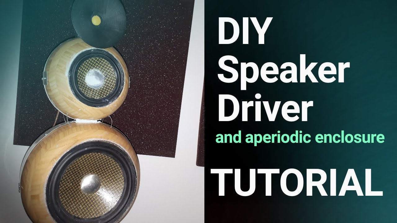
7. Make your own speaker drivers. take magnets from junkyards or copper wire from broken motors, recoat them and make your own field coil speaker drivers, electromagnets can deliver better response than neodymium. To the top end if you make liquefied air or nitrogen, cryo speakers are the most energy efficient speakers to date with impressive speed response, it will remove coil impedance increasing conductivity and the electromagnet will have incredible strength. Also the most important part is light cones, you can make sandwich cones with carbon fiber and epoxy or epoxy-thermoplastic blend.


DIY Speaker Driver Tutorial (Aperiodic 3-way Loudspeaker from Scratch) - YouTube
maxresdefault.jpg

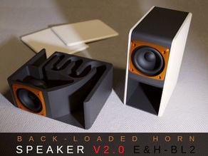
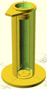
8. 3d printing. with 3d printing you can make the best 3d curved shapes for horn or ported cabinets. you can 3d print a mold and fill it with 
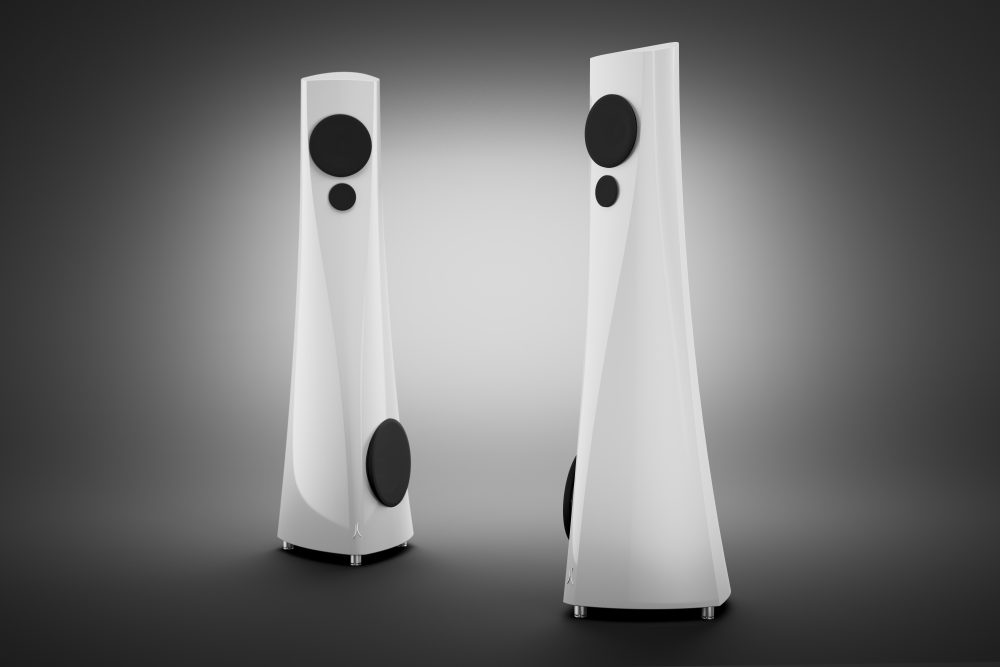
Ultra-High Performance Concrete or epoxy granite. you wont find a better material for speakers.

Back Horn Speaker V2.0 BL2 - Bluetooth, Active, Passive by guppyk - Thingiverse


card_preview_Speaker_V02_01%2B%2B.jpg


Estelon epoxy granite speakers


0100_Estelon_YY_Glossy_White_Cam_01_Light_v004.RGB_color.0000-1000x667.jpg

Help with console speaker renovation

I’ve gutted out the electronics out of a Motorola console and want to use it in my office / man cave room. It was a solid state receiver with a broken phono. I will be using a renovated Dynaco ST 70 tube amp, Pioneer RT707 RTR and possibly a tt in the future (preamp to be determined). I just like the look of it and wanted to create some speakers inside of it that would play well with my gear. Each speaker enclosure is 15”w x 21”h x 15”d (2.7cf) and the center enclosure is 26”w x 16”h x 15” deep (3.6cf). I am no audio/electrical engineer but I can follow instructions. The room is small, 12’x13’ and it will be placed center of a 13’ wall. I would like to keep the budget around $500 but can adjust if needed. The drivers that I took out were working and consisted of a 12” woofer, 6” mid and horn tweeter and are marked Golden Voice and I know nothing about them (pictures attached). I listen to everything from Jazz, classical, 70s rock to country. I would like the speakers to be high efficiency so that they can be driven easily.

Attachments

  • 737AAA21-1554-4006-A1D9-55D1F3E214BA.jpeg
    737AAA21-1554-4006-A1D9-55D1F3E214BA.jpeg
    111.5 KB · Views: 186
  • 6A1E4309-004C-4737-9DE2-F25030DDA712.jpeg
    6A1E4309-004C-4737-9DE2-F25030DDA712.jpeg
    105.6 KB · Views: 176
  • 7A3EF661-3B95-4E42-8899-67254D353914.jpeg
    7A3EF661-3B95-4E42-8899-67254D353914.jpeg
    77.3 KB · Views: 228
  • 45F3F6F1-6275-4189-8AE6-79D6FF3C54E4.jpeg
    45F3F6F1-6275-4189-8AE6-79D6FF3C54E4.jpeg
    121.2 KB · Views: 171
  • 56E35DFD-B2DB-44E4-95F1-05B0473C37D7.jpeg
    56E35DFD-B2DB-44E4-95F1-05B0473C37D7.jpeg
    143.5 KB · Views: 167
  • D5F65456-0883-4E8D-8B35-D2F4711F5057.jpeg
    D5F65456-0883-4E8D-8B35-D2F4711F5057.jpeg
    113.2 KB · Views: 103

Double PCB LM1875 problem hum need help

Hello everyone,

I have 2 purchased PCBs already assembled made by Zero Zone.

I have only one toroidal transformer of 100VA (18-0-18v), the transformer has no ground wire. If I plug in a mono PCB at a time, there is no hum, but as soon as I add the 2nd, the hum appears.

Screws on PCBs don't seem to have any grounds, so that suggests to me that PCBs aren't grounded. In addition there is a separate rectification on each PCB.

If you have any suggestions or ideas that can help me, that would be much appreciated. I also want to mention that I am quite new to electronics.

Thank you.
Denis.

Attachments

  • 20201126_141928.jpg
    20201126_141928.jpg
    1 MB · Views: 350

Mezmerize DCB1 and VSPS phono 1 transformer

Hi, I am a beginner. I have an Antek AS-1215 - 100VA 15V Transformer with dual 15v secondaries and 2 bridge rectifiers (KBPC2504T) ready. I want to use this transformer to power both the DCB1 preamp and the VSPS phono pre from RJM audio. Problem is the VSPS phono preamp calls for rectified dual rail DC while the DCB1 wants center tapped AC. How can I accomplish this? I have attached schematics for all these.

I know I can't obtain +Vcc - 0 - -Vcc for the VSPS using the bridge rectifiers if I first connect the xformer secondaries in series for the DCB1. I think I need to connect the secondaries to the bridge rectifiers first and then I can power the VSPS. I think I can then connect the DCB1 to the rectifiers as well. The rectified DC power will then go to another set of bridge rectifiers onboard the DCB1 pcb--will this be a problem? My only thought is one of the diodes in each pair will be constantly blocking DC and could get too hot?

Thank you

Attachments

  • AS1215.PNG
    AS1215.PNG
    87.7 KB · Views: 209
  • VSPS suggested PS.PNG
    VSPS suggested PS.PNG
    49.2 KB · Views: 185
  • VSPS phono schematic.PNG
    VSPS phono schematic.PNG
    86.5 KB · Views: 200
  • DCB1 Schematic.PNG
    DCB1 Schematic.PNG
    48 KB · Views: 218
  • plan.png
    plan.png
    25.9 KB · Views: 206

NAD 2200 in protect mode

Hi all
I have a NAD 2200 that is stuck in protect mode. I’ve had it For over 20 years and it has some sentimental value so would like to get it up and running again. I turned it on after a few months being off and the relays had a few attempts of clicking On and eventually stopped.
I’ve checked all fuses and can’t see any burnt out parts, the caps aren’t bulging. The relays have been replaced with fully sealed versions at some stage and don’t believe they are the culprit as when fiddling I must have grounded them and they clicked on and off. DC offset before the relay seems within spec. I’ve measured the voltage in a few different spots and found it to be high (see image).

An externally hosted image should be here but it was not working when we last tested it.


My electronics knowledge is pretty low so sorry if I ask some stupid questions. Firstly, am I looking In the right spot? Does the voltages suggest a particular part I should be checking?

Cheers for the help!

Ditton 44 Crossover Schematic

Hey all,

I just picked up a pair of Ditton 44s super cheap as a project. The cabs are a bit rough, the grilles are currently covered in a thick velvet curtain material and the tweeters have been replaced by some truly horrible Motorola things, so I have my work cut out!

I've ordered some Seas 19TFF1, speaker cloth and some wool felt for the front baffles, next up is the crossover.

I've heard mention in all the usual places of an upgraded crossover design by Istari_knight, but the posts are fairly old and the images are dead. I don't suppose anyone has a crossover schematic for the Ditton 44s with a Seas tweeter?

Thanks!

Early NAD 3020 fried channel

Hi everyone,

I'm restoring a venerable old NAD 3020 series 20 (silver one first serie). I got everything done (full recap, changing transistors on the regulator board witch where fried, installing new 2n3055/mj2955 pairs) I've setted the bias and offset without any trouble and finally put some music through the amp, perfectly fine for the first 3min or so, then BAMM!, magic smoke on the right channel......🙁

Some precisions on the amp and what I've done:

The Amp is a first generation 3020

nad3020pwr.gif


But some resistor values comes from 3020b amp:

R647/648= 180r instead of 1k2
R635/636= 1k2 instead of 2k2
R627/628= 680r instead of 1k2
R629/630= 330r instead of 390r

There's no D605/606 on my amp (just a strap)

So after changing the caps, repairing the regulator board and controlling every semi on both channels I installed new pairs of 2n3055/mj2955 (they where absent).
I then installed 1R 3w resistors in place of the strap on r653/654 to measure and set bias, I also substitued RX1 and RX2 for 2K trimmer resistors.
The bias setting went smoothly and I was able to get 30mV on both sides (I controlled temperatures of all the fets and no one where higher than 36°). I let the amp warm for 15min or so to fine tune the bias. I also set the output offset to virtually 0 (0.2mV/0.4mV).
All of those manipulation where done with a light bulb tester in case something went fishy. After confirming the bias, I shorted both 1r resistors as per manual instruction.

So after all that I decided to take a listen to the amp. I plugged it directly to the mains and hooked a source to the aux input and started listening with headphone. No problem at all, sounds nice on both channels, at one time I pushed on the loudness button, tried tone pots, everythings fine.....then after 3 min or so, a little plop then no sound on the right channel, and smoke from the amp.

R652 as burnt, destroying c634 in the process, I tested the semi and Q610/612/614 and both the power trans Q616/618 where fried.

The left channel is intact.

Looks like some kind of oscillation destroyed the right channel, as the runaway started when signal was present.

What are your thoughts on this?

Any love for jordan dcr design ?

Besides ian, i can't find many here who actually have made it.

Classical Jordan DCR - E J Jordan Designs

The way i see it is it is 2 x 5" drivers per box, under over, not 1 as baffle step.

A pair of tang band w5-2143 could be a less expensive clone.

I assume the vertical dispersion of a 10-12" (sit down only) but horizontal dispersion of a 5".


So, ideally sit more than 10' away ?

Attachments

  • 2016-10-06-14.07.00.jpg
    2016-10-06-14.07.00.jpg
    312.7 KB · Views: 146

Aleph J power amp. boards

Hello, I'm fairly new to building my own audio equipment and I'm interested in purchasing the Aleph J power amplifier boards. In addition I was going to purchase the softstart and speaker turn-on delay/dc protector combo. Here's my question : Can I use just 1 (one) softstart and speaker turn-on delay/dc protector combo with the Aleph J power boards or does it require 2 (one for each channel of the power amplifier.?.Also, can I use just 1 (one) universal power supply board to power both channels of the Aleph J power boards or would I need a separate universal power supply to power each channel of the power amp. A response is appreciated.

Klang + ton Array Mini

Haven't posted in a long while, small children are a trip.
For my birthday present I'm going to build myself some speakers.

I really like these: Klang und ton Array Mini's. Unfortunately I can't really find much about them online aside from the original article/plans/diagram. No forum threads or anything deeper.

Two Q's (please bear in mind I'm a carpenter I can really do boxes but not circuits):

1: How do I (can I?) increase the impedance? 3 ohms will roast my old Yamaha receiver for sure. Ideally I'd like to pair them to a small passive subwoofer run off the B speaker posts on the same reciever eventually so 8 ohms would be clutch. Is this too complex of a modification?

2. Are these dumb? I like them for their size and ratios and aesthetic. I assume k+t knows what their doing and wouldn't publish a speaker that would sound rubbish. But nobody seems to have ever built them and posted about it.

Beyma 15kx box recommendatio.

Hello, just wondering if anyone has used the beyma 15kx coaxials?
What I am needing is recommendations for what box volume and port size is needed. What i need is something that will be wall mounted behind a acoustically transparent screen for home theater. I need the box as shallow as possible probably no deeper than @250mm external depth. I will use 3 of these drivers in separate enclosures for LCR. Thx
Beyma 15KX | Manualzz

21" versus quad 10" or quad 12"

I'm contemplating building speakers with a giant horn on the front, and big wooferage, ideally out of sight on the back. They would be maybe 24" wide...meaning large enough to fit a 21" woofer, which are from $300ish at Parts Express.

Alternatives would be quad 10" or maybe quad 12" - ah it's good to have choices in this life!

What thoughts do you have about these alternatives? Particulary if the budget was kept at $300ish per 4x10 or 4x12? (But comments don't have to be limited to those scenarios, blurt anything that comes to mind!)

Help modeling a JBL HF driver, 2425, from measurements

For creating an electrical model in LTspice, I am confused regarding calculating the resonance Q out of driver measurements. I need this to get the correct Ls and Cs to model the resonances.

I'd like to create accurate models so I can easier calculate starting values for the XO. (To be adjusted of course in the real life speaker, but when ordering the parts it would be nice to be in the ball park).

My example driver:
So I have 16ohm variant of the JBL 2425, a HF compression driver. I measured the impedance while they were in the horn I got with them. The lowest resonance I guess is the driver's resonance, while the peak just above 1kHz is due to the horn's cut-off frequency. ?
So to design a crossover I would like to model the drivers. I also want to
reduce or even eliminate the two impedance peaks below the cross over frequency (XO undecided but > 2kHz).

Or is that not a good idea, to insert a network to compensate for the resonance peaks? I think it is because the impedance peaks will mess up my cross over network. If I design the cross over for a 16ohm impedance (11ohm measured, so I will use that value) I will end with certain values for the cap and inductor. But the 24 ohm and 40 ohm hump will shift the cross over points down a bit and the humps should therefore be reduced. Or am I over complicating?

When looking at the measurements the 40ohm peak at 480Hz looks to have a Q of about 2. (3dB bandwidth ca 200Hz, and 480Hz/200Hz=2.4) If trying to simulate an LCR using values of R=40 ohms, Q = 2, and frequency of 480Hz, I get L=26.5mH and C=4.1uF. But simulating this in LTspice gives a much too low peak.
Using a lower Q value the peaks tighten up and look more correct. Isn't this the opposite of what should happen? Higher Q should give higher and sharper resonance peak...?
Using Q=0.25 I get L=3.3mH and C=33uF, and the resoance looks pretty correct. But that was from much trial and error, not understanding anything...

My other question is: When calculating the series LCR to be placed in parallel with the driver, to compensate/eliminate the impedance peaks, do I use the driver's nominal impedance of 16 ohms (11ohms in my case), or do I use the measured impedance at the peaks, 24 and 40 ohms?

I want a flat impedance of 11 ohms over the entire band, so I will start off with R=11ohms, and I suppose that means the L and C needs to be matched to 11ohms, and not the 40ohms measured at the resonance. ?

EDIT: Brain-fart... If I want a flat 11ohms, I need to concider the LCR network will be in parallel with the driver, and the driver itself is ca 11ohms. So my network in parallel must have much higher value for the R... hmm perhaps I will just not have this complicated network, I seem to only confuse myself the more I think about it...

Sorry for confusing questions. How would I go about creating a model out of this measurement?

Attachments

  • JBL2425J16ohm.png
    JBL2425J16ohm.png
    96.6 KB · Views: 172

Problem with old vintage russian amplifier мощности п70

Problem with old vintage russian amplifier мощности п70

Problem with old vintage russian amplifier мощности п70
Helo,guys ! In attached diagram I have following problems:
1. Channel no.1 is working well , no.2 is overloaded (huge idle current with R76, R77,R82 factory setting). R82 is variable resistor, not fixed.
2. All 3 T18 pins have 39V
3.T18 pulled out and checked - ok
4. T18 back onboard, wire 23 and 25 disconnected - still 39V all 3 pins
5. Both channels will smoke R77 or R31 if adjusted nearby their end.
6. All T16,T17,T19,T18,T20 checked, all ok.
Did'n ckecked T19 and T20 connections, maybe mixed by some guy , T19 and T20 are previously replaced by KT 809 by other hands.
Did'n ckecked T15 and ahead.
Thks in advance.

Attachments

  • russian vintage P70-05.png
    russian vintage P70-05.png
    910.6 KB · Views: 130

Starting again. LM3886 build.

Hello there

Well after several years missing in action I have found my way back here.

Previously I had planned and built an LM3876 pair of amps. Sadly all this was lost before it could be completed. Though working they needed an enclosure and proper speakers needed building.

So here I am again. No idea what my previous account name was but luckily I have found a few bits on a back up HDD.

I am hoping to be able to use my PCB patterns for this build. Though designed to suit the LM3876 it appears, with a minor change, that the LM3886 can be slipped into place. The main change being to connect pin 5 to +ve.

At the time of conception I had a lot of help, I remember, from AndrewT. Sadly I see he has passed on in the Intervening years. Rest well and thank you for all your help to the community and myself Andrew.


Here are the main parts I have recovered. The PSU PCB and associated regulators will need redoing. But that’s all.

Regards

Audible Click.

Attachments

  • 8A85EABA-F433-4C65-B21F-FA2EF5373A14.jpeg
    8A85EABA-F433-4C65-B21F-FA2EF5373A14.jpeg
    226.8 KB · Views: 650
  • LM3876_Parts_List.pdf
    LM3876_Parts_List.pdf
    65.8 KB · Views: 81
  • Wiring2.png
    Wiring2.png
    28.8 KB · Views: 648

Bridging a Son of Zen style amp?

Hello All. First and foremost, I am not sure I am posting in the right forum. I based my circuit off the son of zen and Mr. Pass's talks, so I think this counts. If not, I apologize in advance.

In any case, I am wondering if it is possible to bridge a son of zen style amplifier.

I am working on a sort of upside down son of zen amp with aleph 5 kind of power. It will work for my current speakers, but if I ever end up getting magnepans, I would love to build a second one of these and use it as a mono block.

Here is a super simplified version of my circuit.

Attachments

  • bridged amp.png
    bridged amp.png
    43.7 KB · Views: 196

Please,!, Help picking slim 2.5 or 3-way design kit

Please, please, please help.... I am so overthinking things, I have decided this is the only way to convince me which speaker design / kit to build - YOU. This is mostly because I cannot hear any of these kits so I am relying on you to guide me to a quality kit that will sound great.... not just okay (within my budget).

I am looking for a kit to build because I do not want to deal with xo design. EVERYTHING else is buildable and re-designable for me and my abilities.

Budget is $1000 for a finished project but I can easily bump that up if sound quality will be a noticeable gain.

I need a tweeter on top design
I need it to play to at least 40hz +/-
I need it less than 40” (but I can redesign the lower section if necessary to fit under my tv).

I would like a narrow design but I would be okay with a side fire woofer too.
I would like a three way design (I’m pretty sure?)

It will be in a corner (front / side port?)
It will be powered by an AVR 4 ohm stable
Phantom mode
No sub
large room
Tv and some music.

IMG_3983.jpg


FYI- I have been scouring internet for the last week so please do not recommend a website, Please recommended a speaker kit.

Or is there another route I haven’t found that doesn’t involve xo building / science-ing?

Thank you, Chad

Ceramic Speaker enclosures

In the past year I have become skilled at throwing forms on the potter's wheel. I want to make a speaker enclosure out of clay.
The ideal shape of a speaker enclosure is a shpere. I could make a round shape easily on the wheel, make a perfectly flat space to mount the driver at top, and presto! I have a round speaker enclosure. I can stand it on some legs so the woofer faces forward. I can even make a little enclosure for a tweeter or mid, attatch to two shapes, and stagger for time alignment. Many possibilities. What do you think?
-andy

New 15 " Scan Speak transducer with elliptical VC

TG's latest report features a new Scan Speak speaker with an elliptical voice coil, this time a 15-inch twoofer driver.
It is interesting to read the opinions about it when the first model came out:

ScanSpeak-Ellipticor-1


" The aim of elliptical voice coils is obviously to break symmetry. The force applied to the cone through the voice coils usually sees the same distance from the edge of the voice coil to the surround, thus inevitable break-up modes occur and we may have high-Q resonances disturbing frequency response and phase performance."


And now :

" Since April I've had the pleasure of playing around with prototypes of ScanSpeak 38WE/8582T00 driver, the most sophisticated 15" bass driver ever made. Elliptical voice coil and a powerful very open magnet structure. This is not a subwoofer, but a bass driver featuring a fairly light-weight paper cone, delivering agile powerful bass from around 100-150 liter cabinet volume."


Speaker Talk


What do you think? Can elliptical VCs be considered a revolutionary step in speaker design?
Are investments in this new technology justified (audibly) by SS ?

They look very well built and pretty ! 🙂

38WE/8582T00 – Scan-Speak A/S

Edcor transformers DCR?

Just wondering if anyone has the DCR measurements for Edcor output transformers?

Looking for the DCR for the 1.25K, 3.75K, and 5K SE output transformers? The larger ones. The CXSE line.

I emailed Edcor and their response was we don't measure this. Even though how hard is it to throw a multimeter on the transformer and post it on the website?

I will assume a 5-10v drop across these... going to be running 100-110mA

Thanks!

[Class H Amplifier] BRZhifi quick review amplifier

Hi amigos,

Just want to share some pictures of my new toy )
I took some risk when buying this amplifier... but when I plugged it : wouaaaaaaaaaa ! I am am absolutely surprised how good this amplifier sounds for its price ! I come from Class D world... see my review about high end TPA3255 / 51 and other class D amplifier (Hypex NC250 / NC500MP) etc...

This amplifier blew me away regarding Medium and Tweeter :
reproduction of mid and high frequencies seem to be very very good.

VS my Hypex double Mono NCore : it is less present in the bass but the treble and mids are more forward, the notes in these frequencies are absolutely incredible

VS my high TPA3255 by DrMordor (with PFFB OPA1602) : the bass is also less indented and drier. As for the midrange and treble it is the same observation, excellent rendering, especially on plucked string instruments and cymbals.

This amplifier is absolutely dead silence and noiseless.
Really well made, seems solid. full alu case

Spec :
Toroidal PSU
EPCOS 5200uf caps / Nichicon
RSN312H24 audio Chip
THD : 0.01%
SNR : 100DB
70W / 8 ohms
Omron relay
CSR8675 BT Aptx HD
Alps potentiometer

IMG-20201009-190026.jpg

IMG-20201009-185914.jpg

IMG-20201009-185829.jpg

IMG-20201009-185848.jpg

IMG-20201009-185900.jpg

Lid Hinges for Linn (LP-12) Thorens and Sony Turntables - repair?? orig. brand wanted

I want to know the brand name of the manufacturer of bad quality springed lid hinges (dust cover hinges) for Linn record player (turntable, e. g. LP12)
Type: 2F-037/H (2-F-037-H)
identical to Sony part, number "4-852-704-11" (appropriate for the turntable models PS-T3, PS-T33, PSX-45 and PSX-55S)
and Thorens TD320, TD318, TD147.

I need this brand name for catalog ordering to find out robuster springed version in top quality but in the same sizes.

Here some images of the worse original versions:
http://www.melodia.co.jp/linn/file/2F-037-H.jpg
http://www.russandrews.com/images/products/7504l.jpg

and a explicit repair instruction of a Linn Sondek dust cover hinge repair
Linn Sondek Dust Cover Hinge Repair - Club Polk
Linn LP 12 Dustcover Hinges - SH Forums

To know the name and address of this hinge brand would be very interested (also for guys, who intend to create their own high end record player). Perhaps the brand of the Linn orig. Part 2F37H offers a wide range of such dust cover hinges from cheap to expensive respective from low quality to top quality. Because the hinge version from Linn Sondek was used from much other companies, the manufacturer must be a good known brand name.

Thank you very much for your advives.

LXmini centre speaker proposals

Having searched for and not found anything to match my LXmini's (built from a Magic521.com kit) as a centre speaker I have come up with a couple of ideas. Of course a third LXmini would be nice, but the height would impinge on the screen, so that's a no-goer. I need a version around 38cm shorter and to retain the same tube length and volume, decided to use concentric tubes, effectively forming a folded tube.

The first design sticks closely to the original Fernco based design, basically adding a larger outer tube. The second shrinks the inner tube diameter to match the 90mm of the woofer magnet which now becomes the far end of the tube and is sealed by the magnet via a gasket. The outer is now the end acoustically closer to the driver, with the biggest difference being the elimination of the Fernco. Not sure if this is a good or bad idea, SL noted he never tested alternatives and it looks like his design used off the shelf plumbing parts for convenience. Anyway, in the spirit of experimentation encouraged by SL, my two suggestions are attached

Would appreciate feedback from anyone with actual experience with any of the concepts here, good or bad - it could save me wasted effort!


And please: do not suggest phantom centre, it doesn't work other than with a small sideways range of the sweet spot.

Attachments

  • LXmini-minor1.jpg
    LXmini-minor1.jpg
    51.8 KB · Views: 73
  • LXmini-minor2.jpg
    LXmini-minor2.jpg
    44.9 KB · Views: 80

CNC Wood Cutting in UK (Speakers Cabinets)

Hello All,
Just to let you about a UK Midlands based Timber and Hardware business that has a sheet cutting CNC machine/service.
The companies name is A J Philpott & Son Ltd in Fountain St Fenton, Stoke on Trent. ST42HA
I had a chat with Gareth who runs the CNC machine if he would be interested in taking orders like cutting out speaker enclosures and shipping them to DIYAudio members and he said yes.
So if you need a couple of speaker enclosure CNC’ing out, Gareth at Philpott’s would be worth a try.
Their phone is UK 01782 848603 or email at gareth@ajphilpott.co.uk

BTW I have no commercial interest in Philpott’s , I am just trying to help people on this forum and a local business.

6b4g amp mystery

A friend of mine bought an amp in an exchange or similar a while back from a chap and then lent it to a friend as it was very low power, and not appropriate for his speakers at the time. Now he has horn speakers and got the amp back he's trying to understand the circuit and make sense of possibly improving it as it currently sounds...well a bit average.

Pictures attached, any idea how to sensibly deduce the circuit?

Neither me or my friend with the amp really have much of a clue to be honest!!

but very eager to learn 🙂

Attachments

  • IMG_1486.jpg
    IMG_1486.jpg
    756.9 KB · Views: 504
  • IMG_1483.jpg
    IMG_1483.jpg
    599.4 KB · Views: 502

DIY anamorphic lens

I thought I'd start an anamorphic lens topic for any AVS Forum members browsing around or anyone else interested in the topic.

First off, here's a link to Tor Arne's site describing in great detail his construction of an anamorphic lens (several actually):

http://home.c2i.net/ahustvedt/arnemorph/

For you German speakers, here's a link to the site that did the original R&D on the lens:
http://ww2.bepo.com/jochen/anamorph/

I think there's a link there to the German discussion forum where the original ideas were hashed out. Sorry, I don' t have it handy and don't speak German well enough to find it.

There's also some interesting info on prisms and anamorphic lenses here:

http://appft1.uspto.gov/netacgi/nph...p=1&u=/netahtml/PTO/srchnum.html&r=0&f=S&l=50

We've been moderated out of existence on the AVS Forums so I'm hoping some of the other 'rejects' from there will come over here and we can get a good discussion going.

For sale: Korg B1 enclosure with parts & wiring

Hello,


for sale a Korg B1, fully finished with the stock parts, but Duelund DCA signal wiring, without the B1 board.


I have used this for 3 months. Dead quiet, no ringing or any other problem. Reason for sale is, I build me a 4 channel version. Sale is without the B1 board, will turn that into an integrated amp.


As said, comes fully wired, Alps pot included. All you'd have to do is mount your own board -nuts and bolts supplied- and connect the signal- and power cable to the it, and you're good to go.


An externally hosted image should be here but it was not working when we last tested it.


An externally hosted image should be here but it was not working when we last tested it.


An externally hosted image should be here but it was not working when we last tested it.


All metal is 5 mm aluminum. Top plate is removable for easy access to the measuring points and variable resistors. W*H*D = 130 * 275 * 70 mm. Pictures don't do it justice, it's a nice looking little thing.


Make me a fair offer, and it's yours. Am from the Netherlands, so shipping cost is a thing. Weight is 1 kg.


Greetings, Bart.

RIP: Jeff Bagby

Just found out Jeff Bagby passed away from a Facebook post.

Javad Shadzi‎ posted this today,

Everyone, it devastates me to tell you that Jeff Bagby passes away this morning.

It just keeps hitting me in new and profound ways at how much he’ll be missed, I’m really struggling to find any words to describe how terrible his loss is...

He was one of the most remarkable people I’ve ever known.

Please share a sympathy or memory about what Jeff meant to you, if you ever had the chance to know him you’ll likely have a story about how he touched you.

Anybody in the UK want a discarded Bose Project?

I've had a Bose Companion 5 subwoofer cabinet and driver on the shelf for almost a year.

I will never do anything with it.

I was very specific when I said 'cabinet' and 'driver' because the plate amp is missing.

The bad news: For those with limited experience of Bose I should explain the issues. The front grille is glued into place, there is no access to the driver. The PSU is sealed inside the cabinet it cannot be accessed without destroying the unit.

The good news: the PSU and the driver have been tested and are perfectly functional.

The dilemma: Bose claim the system to be 300w. A 300w toroidal PSU is not be sniffed at. I can use it in other projects. I am minded to take a hammer to the case to retrieve it.

However, if anybody wants the unit before I destroy it, they are welcome to it for the cost of shipping.

Attachments

  • Bose5rear.jpg
    Bose5rear.jpg
    522.3 KB · Views: 126

same LED brightness from different stages?

Hello everyone, happy new Year!

I was thinking about bringing every LED from my amp (F4) to the front-panel.
That is, 2 from the universal PSU, 2 from the amp-channels, and (?) 2 from the speaker protection (if they light up at all) - so 2 or 3 different sources.
Brightness will be adjusted through resistors.

Will their respective brightness be the same (with the same resistors), or will they vary depending the source (PSU/OS), and I'll have to experiment until it's right?

The resistors can be with the led on the frontplate, right?

TIA
david

Bluetooth headphone amp/dac

Happy New Year tweakers!

Has anyone had any success in adding Bluetooth to something like CMoy or O2 amps?

I'd like to use my Grado 125's with my smartphone as a source and thought if I could add a BT module I'd get around the fact it doesn't have a 3.5mm jack.

Any thoughts? Or is this when it's just going to be easier to buy something ots?

Thanks in advance

Michael

Super Regulator, collecting the facts

Jung Super Regulator, some facts

Hi!

I wonder about a few things regarding the Jung Super Regulator:

How fast does it start with the original component values?

Does it work for negative voltage using AD797, assuming all signs have been changed, NPN->PNP and vice versa?

What happens when you have current limiting and the voltage is below min voltage for the opamp?

Yet another IDS-25 clone?

I’ve fallen deep into this rabbit hole after stumbling the other day onto roger russell’s website. I need to experience this for myself, so figured I should start my own design/build thread.

I’ve read pretty deep into wesayso’s trials and tribulations, and learned a fair bit about a few major pitfalls...

Lots of places to start here, the drivers being one. I’ve got some looking to do and to decide what is the best price to quality ratio that I can afford at the moment. The Dayton audio PC83-8 looks like a possibility, along with the ubiquitous Vifa speakers used in the original and by many others.

I’m planning at the moment to go with a simpler design than the two black towers. I’ve done enough woodworking to know not to fight the natural inclinations of wood, and I also don’t want to turn so much material into sawdust, even though I can get Baltic birch ply for very good prices (cheaper than all the home center crappy ply by a good margin). I prefer dark woods like mahogany and walnut, but need to figure what I want to live with. Laminating steel or aluminum to wood is also an option, and would deter the cats from using it as a pair of monumental scratching posts 🙂 I’m a sculptor by training, so i’m looking at this as an opportunity to build a functional piece of art, though function and good sound are more important to me, I will have to look at these things.

Choosing an 18" driver for a Large Ported Box

I have a large open floorplan basement (6000+ cuft / 170 m^3) but don't plan to listen anywhere near reference (-20 or -15). Maybe 70% HT / 30% music. I can get 2 boxes of any size, so I was looking at Full Martys (11 cuft ported tuned to 16 Hz).

I'm trying to understand out the tradeoffs between various drivers (UM18-22, SAF184.03) in a full Marty.

From looking at some performance comparisons (e.g. gsg's table on their website, though perhaps I could learn how to use WinISD), it seems at these sizes the enclosure and port largely determine the low frequency extension and volume (for HT). So while the focus is on HT, it seems like I wouldn't gain that much ULE by going with say a Dayton UM18-22 vs B&C TBW-100 or lavoce 18" (SAF184.03): seems 2-3 dB at ~20 Hz but similar extension down to 14 Hz.

I would gain a lot in mid bass volume (though I don't listen very loud) but also quality? I've seen talk about the bass quality of these pro drivers, perhaps related to distortion and the lack of heat due to their efficiencies. Or is it not worth losing the Xmax, especially for an enclosure of this size? I will be using MiniDSPs and REW. Being able to use a weaker amp is also a bit enticing.

Any links for trying to understand this is also welcome.

Yamaha RX-V357 amplifier, no display, no diag mode-only power relay toggle click

I have an Yamaha RX-V357 that suddenly stopped working , no protection mode , no display , no diag mode - only power relay toggle (clicking on and off).

I've already disconnected power stage voltages in order to avoid any output / speaker DC protection and also power relay is by-passed in order to have all voltages ready-to-be-checked from power transformer.

Almost all voltages seem to be correct, except 5MS that missing. If 5MS externally provided no more relay clicking but still no display.

Any help ?

Attachments

  • Yamaha-post-01.jpg
    Yamaha-post-01.jpg
    275 KB · Views: 486

DC output offset of STK 403 and PS PRT Yamaha-rx-v357 protection

Helo,guys ! How can I control DC loutput offset of STK 403 , I have an Yamaha-rx-v357 and all STK have 1 V DC offset on output, otherwise sound is clear if protection is deactivated...

I've found on Google : "I found that the +/- Pre voltages were very important in setting the DC offset on the output."

On Yamaha-rx-v357, what does it mean PS PRT:16% - wich is normal range for it, wich is IC 242 pin for it , wich is the reference for it ???

Buffer circuits, aren’t they?

The circuit on attached is a contour (variable loudness) circuit of Nakamichi 410 preamplifier. I’m wondering that why they used two sets of 22uf capacitors and 100kOhms resistors; C501, R501 and C503, R503. Are these components be buffer circuits? And why didn’t they place them after the switch to reduce the components, using only one set of R and C instead of using two for IN and OUT switch position?

Attachments

  • C1C74404-66D2-4D0B-A84C-563FD1B255C0.jpeg
    C1C74404-66D2-4D0B-A84C-563FD1B255C0.jpeg
    249.2 KB · Views: 305

Noob needs help with a MusicAngel preamp

Hello,

I bought a re-furbished pre-amp which initially worked fine. Then I replaced the tubes and something got messed up

EST » TOOTEKATALOOG

This is it, a MusicAngel device using 12ax7 x2 and 12au7

I replaced the original tubes with 2x Tung-Sol 12AX7 and 1x Electro Harmonix 12AU7EH

There was only really quiet sound from right channel. When I put back the original tubes, the sound came back but was crackling.

Did I break it?

Thanks for any response!

Understanding Grimm Audio XO

I find their approach is very interesting.

http://www.grimmaudio.com/whitepapers/speakers.pdf

1. EQ the drivers beyond operating range to flat

2. Apply the intended crossover, eg. LR4.

3. Apply time delay.

So far so good. But what about this 4th step, quote ..

Finally, the icing on the cake. The sum of an ideal LR4
system is a second order all-pass with a Q of 0.7. In order
to avoid the problems associated with correcting
phase exactly, build an inverse all-pass filter based on
the theoretical ideal. This filter will be non-causal so
there’s a good reason for using FIR.


Questions:

- What do they mean by " The sum of an ideal LR4
system is a second order all-pass with a Q of 0.7" ?

- What do you think " an inverse all-pass filter based on
the theoretical ideal" ?

If this can be realised using MiniDSP it would be great I think.

Speaker Cabling, different metal +ve vs -ve?

I have a number of speaker leads on hand, but one particular pair of leads have copper coloured multi strand wire in the +ve path, and silver coloured multi strand wire in the -ve wire.


None are magnetic.


Is this an issue?


Could these wires have different conductive properties which could either affect sound or cause issues with electronics such as the Amp?


thanks


Cliff

Subwoofer for Frugel-Horn XL

Hello all and Happy New Year!

I am contemplating a new build, a subwoofer to complement my Frugel-Horn XLs. The Frugel-Horns don't necessarily NEED a sub to go with them, but I think they would benefit from one. I'm not looking for cheast-crunching pressures, just to give a bit more kick to the kick drums and some more groove to the bass lines. More than anything this is me wanting another project...

From an aesthetic point of view, a down-firing design would be quite suitable. It would also be the easiest considering there is a young puppy roaming around having a taste of everything with is very pointy teeth. In terms of acoustics? I have no idea.

I have Hypex DS1.2 amp on the shelf, which I'll happily use for this project. With the MiniDSP DDRC24 I expect I can pair the sub nicely with the Frugelhorns.

When it comes to choosing drivers or designs, I don't have much of an idea where to go to accomplish my goals. I'm hoping to find a ready, or easily modifiable design that I could use, somewhat like the Frugelhorns themselves were.

All input will be greatly appreciated!

New year trouble shooting a KT88 output stage

I've built an amp similar to the two stage mono Bill. My issue is that when I load the output transformer the output voltage reduces significantly. The amp just can't drive a load, about 8watts max into 8.5 ohms (dummy load).
The HT is 460V, quiescent current 50mA. (GEC class AB1 ultralinear fixed bias conditions which should give up to 70W with anode to anode of 4k ohms)) Fixed bias is from Tent Labs auto bias circuit. I've also tried configuring as a basic cathode auto bias circuit, but the problem is the same (I don't think it is the Tent Labs circuit causing the issue). I've tested the driver stage when the amp is under load and it maintains its drive voltage. The output transformer is a discontinued Sowter 50W UL unit, 4K a-a, 40% taps, four output windings that can be configured for various loads. I've measured the primary winding dc resistances and they seem OK. I also applied 50Hz ac to the secondary and measured the primary (no loading) and calculated the anode to anode impedance which came out at about 3.8K ohm, a bit lower than that specified. I've tried configuring the secondaries according to manufacturers recommendations and every other which way, to try and get load tolerance, but with no success. I've also tried other, known good KT88's. I've tried varying the HT and bias with no improvement. So on the face of it, it seems a problem with the transformer, but if it is, the failure mode is odd as it appears OK on all static tests. Any ideas? Thanks. Matt.

Sowter 50 watt UL transformer connections.jpg

Sowter 50 watt ULtransformer.jpg

monobill_2_schema_versterker.GIF

Control Foobar2k through Bubbleupnp

Hi fellow audio mates
Can someone help me re-configure bubbleupnp server and necessary foobar2000 settings to have bubbleupnp up and running on my android tablet to control f2k?
Until recently I had everything setup correctly then I changed over to a fanless mini-pc and I can’t make it work any more!
Is there a step by step set of instructions available somewhere?
I have the bubbleupnp server installed on the same mini-pc along with f2k
Thanks in advance!

Quad 405 MK1 --- C4 Orientation

I am applying Dada mods to my Quad 405 MK-1. My boards are M12368 Issue 10.

Please see attached pictures of Schematic and board lay out from service manual.
Now compare it to Picture of board by DADA , specifically orientation of C2.

Which one is correct?

I have looked at different websites, like Keith Snook, deSmith etc and everyone advises to change the capacitor but no one advises to reverse the polarity?

Many Thanks in advance for your guidance.

Attachments

  • schematic.PNG
    schematic.PNG
    528.5 KB · Views: 837
  • board.PNG
    board.PNG
    408.2 KB · Views: 445
  • dada.jpg
    dada.jpg
    110.4 KB · Views: 514

Modified Van Waarde OTL HPA w/ 0D3 regulator

Hello diyers,

Having a handful of kits under my belt, I am looking to embark upon my first scratch build -- a tube headphone amplifier based on the Van Waarde design, tweaked based on some comments from user audiowize in a thread here, substituting a 5687 tube and tweaking the plate and cathode resistors to reduce the gain.

I am aware of the limitations of OTL tube amplifiers in driving low-impedance headphones; my primary application for this will be driving 600 ohm Beyer DT880’s. I know this isn’t the end-all be-all of designs -- I like that it’s simple, with a relatively low parts count, and seems like a fun first scratch build project.

Here are the design constraints that I’ve set out for myself:
  • Single-chassis design, preferably not too large (considering a 10” x 5” x 3” or 9.5” x 5” x 2” Hammond enclosure)
  • 0D3/VR150 shunt regulator w/ MOSFET to provide the ~150VDC B+ (I need that beautiful blue glow in my life) based on this circuit and this thread
  • Heaters to be run on elevated AC
  • Solid state rectification
  • Reasonable budget (as always, I have to set aside a large portion of it for new tools 🙂 )

I’ve attached the schematics and a screenshot of the PSU design and single-channel schematic.

I was planning on using the following real-world parts in the power supply:

From my simple simulations, it appears that at quiescent current the L-C filter I’ve simulated in front of the 0D3 regulator will reduce the ripple to about 175mV (peak) and the regulator and subsequent 47uF cap will further reduce it to 100uV. (I substituted a Zener in the simulation because I don't have a model for the 0D3/VR150 tube.) The LTSpice sim shows only 45uV on the output.

What does everyone think? Am I missing anything obvious here? Any feedback is welcome. Will post build photos and tests as I progress.

Attachments

Stupid question about Helmholtz resonators

So there are all sorts of calculators for port length/area/volume etc. but we're tuning for some very low frequency such as 32Hz which has a wavelength of 30-ish feet but the ports are designed to something much higher frequency. They aren't 30ft in a typical vented enclosure design. Sure, you deal with half wavelengths in room gain, but how in the heck can you somehow boost 32Hz with a tiny (relative to 30ft) port? If I guess correctly, the "1st resonance" is the actual Helmholtz resonant frequency of the port which makes sense...200Hz, etc., but it doesn't seem like you can get a resonance from ~3 octaves below that. A Helmholtz resonator resonates at integer multiples of half the wavelength (right?) and is why you get the crazy resonances at increasing frequency in (for example) Hornresp. Every frequency that is an integer multiple of the Helmholtz (1st resonant) frequency is a resonant frequency, but they have to be higher than the 1st resonant frequency. But to get a resonance at 32Hz from a resonator designed for ~200Hz means you're dealing with fractional (not whole number) multiple of the half wavelength.
I'm sure the explanation is simple. But what is it?
Link to the inevitable thread discussing this is welcome.
Playing with my new table saw with my son's new sub enclosure and still have 10 fingers (born with 10)...

recommended 24v PS for Naim phono stage?

Hi,

I purchased a used Stageline N Naim phono stage. I don't have other Naim gear or a PS for it. What's a good 24v PS to get the best out of the Stageline?

After opening the unit, I saw 10 of ZTX384/ZTX214 transistors per channel.

Some options are:
Jung/Didden Superreg
TeddyReg
Classic PS, similar to Naim designs.
and finally: Should I use a dual mono PS since the Stageine has a pair of "+ V in" on the the DIN connector? Is this separate power sources for each channel?

Thanks,
Herman

Home brew tube amp problems

I decided to dive into the world of tube amplifiers by building one. I researched how they work, and found a schematic I would use as a starting place. I chose the AC-568 bassman, but I had some changes I wanted to make. I gave it a potentiometer on the tone slope resistor, added a mid control, and gave it a class A power amp. I only used the bass channel, and the input with a resistor going to ground. I added a 4th gain stage too, simply because I still had half of a 12ax7 available. The first time I turned it on a few things happened..
  1. It hummed very loudly
  2. the guitar signal was patchy, thin, and very distorted
  3. It made a bit of a "pop" from the speaker and went quiet

A few hours with the oscilloscope narrowed it down to the 3rd gain stage, and more specifically the tube. there was signal through the whole line until the plate. I moved the wire on the screen of the 3rd gain stage to the screen of the 4th, eliminating the 3rd stage if I'm correct. I tried it again and now I just get really loud hum, and no signal. I haven't looked at it with the oscilloscope yet, but I can't quiet the hum with the ground switch or the volume. My best guess is that I have a ground problem, but that's just a guess. This is the schematic I drew, I know it's a mess but better than nothing. Bass amp prototype by adhehl | Upverter Thanks in advance for any help, sorry for the long post!

SE power amp as headphone amp?

Hello,
While I'm quite happy with my "portable" player with 2 TPA6120 at the end, for best results at the main listening spot, I'm still searching for the best amp I can make. I was looking for a decent single ended class A design with transformer output, but yet could not find.

I had another project, started as low power guitar amp, but started on a hifi amp, again single ended class A with transformer output. During the project I realized it is a complete failure for guitar amp, so I built it as a hifi amp. It ended up very impressive. Not far away from my 2A3 PSE.
I also have an OTL headphone amp, with 6S19P at the end, I call it a monster and on cold evenings I was thinking to put it under my armchair, to have some additional heat 🙂
The 807 ended power amp makes less heat actually and it is very safe for the speaker (headphone).
Now, I was thinking, I put a 8 Ohm resistor load at the output and connect the headphone. It is heavier, but stable and less power hungry.
What do you think?
Do you guys have experience using tube power amp as headphone amp?
How would you make the load? I guess with several small resistor. For example 20 times 160 Ohm in parallel?
Thanks,
JG

IMG_3756.JPEG

NIB Amperex E88CC 6922 PQ, Mullard E88CC 6922 Gold Pin, Brimar 12AT7, Mullard ECC82

Clearing out great quality small signal tubes that I have accumulated over way too many years! All of these tubes are new old stock in their original factory boxes. All test NOS on a calibrated TV10/U Navy tube tester. The pairs are closely matched and have balanced sections. (The Amperex PQ’s are the most closely matched.) I have a few pairs of each E88CC/6922 tubes.

Amperex E88CC 6922 PQ $100 per matched pair

Mullard E88CC 6922 Gold Pin $125 per matched pair **** all sold or pending payment****

Mullard E88CC 6922 $100 per matched pair **** all sold or pending payment****

Mullard E88CC 6922 Made in Holland, single tube $50

Mullard ECC82 (12AU7) $75 per matched pair **** all sold or pending payment****

Brimar 12AT7 (ECC81) $60 per pair


Buyer pays USPS Priority Mail. insured. Shipping to North America only. Tubes will ship within 48 hours of receipt and verification of payment. I will ship only to a verified PayPal address. Payment must be received within 3 days. Shipping cost is the actual USPS price. Please contact me if you have any questions before you offer. The tubes will be very well packed.

They are vintage tubes, so sold AS-IS. Sorry, NO RETURNS
O9XMRyw.jpg
[/IMG]
5KFzWch.jpg

M2XSWjF.jpg

GuU6R3k.jpg

OAuGtdp.jpg

Kenwood KAC-X401M Amp need help

I have tried to attach a schematic.

This amp has a CPU which keeps powering off the unit. When I power the unit it starts and makes 65volts + & - about 5 seconds later it shouts down. In the diagram Q20 & Q21 are part of the Protect circuit and Q21 stays at 5V. Q20 has 65volts on the Base and Emitter and .001volt on the collector. I also replaced the 5.1 zener although it checked out.

There is .04 volts at the most on the outputs but I don't think that would shout it down. I did find diode D32 across the relay to be shorted and replaced it. I have also pulled all outputs and checked them ouyt of the board(they were fine).

Please help me with any ideas.
Thanks Jeff
Projects by fanatics, for fanatics
Get answers and advice for everyone wanting to learn the art of audio.
Join the Community
507,772
Members
7,887,848
Messages

Filter

Forum Statistics

Threads
406,201
Messages
7,887,848
Members
507,772
Latest member
Hypertone