Crown CTs2000 and CTs1200 both dead

Hey all,


I have a Crown CTs2000 and a Crown CTs1200 both of which are dead with a similar fault, though the 2000 has a few extra parts that were suspect. The varistor in the power supply right after the bridge rectifier is blown on both. This is a part that on schematics of the two units, there are notes that that part should be removed. (these units are from about the 2002 vintage)


Has anyone here had similar experiences and could anyone here give me guidance as to if I replace maybe the filter caps and main relay and leave the varistor out as per the update notes, would that safely get the amp working again?


-Nicholas

Is the cld baffle construction canceling out the 4" midbass HD? t

I made a strange observation today, potentially involving my 5 layer cld baffle.

Two measurements, on axis, both at 100db/12".

The first is of my Peerless hds 4" midbass mounted on on my 5 layer cld baffle and the second is of my 10" peerless xxls subwoofer. Can anyone make sense of this? Am I missing something? Is it even possible? The brown trace on the sub is the noise floor.

Attachments

  • driver thd.jpg
    driver thd.jpg
    90.6 KB · Views: 349
  • subwoofer distortion.jpg
    subwoofer distortion.jpg
    106.4 KB · Views: 358

EL84 / KT120 Design questions

So i know i have posted a few threads on here and jump around a bit on what my next project will be. But here is the final one. It will be a KT120 SE UL with switchable triode / UL and switchable feedback 0,3,6db . The KT120 will be run at 400v, 105mA, and 3.75K load. Cathode bias. The EL84 driver tube will be run at 400v, 8K load, 200vp, 150v screen, 25mA. The driver will have diode / LED bias and also a unbypassed resistor for global neg feedback. The feedback is taken from the secondary of the OPT.

All iron is Edcor. Dual mono blocks. 400-0-400 / 200mA power transformer. 2x 2H/29ohm chokes per channel. See attached images. One is just the power supply (mono bloc), the other is ripple for the output stage. The PS caps will be ASC oil caps. 5U4 rectifier tubes. Any good places to get the ASC caps? Allied?

Power output will be approx 10W triode, 20W UL (only according to online sims).

Could you look at the Power Supply sim and let me know if there is any glaring issues? Thank you!

More details to come... once i start building it! Probably bread board it first.

Attachments

  • PSKT120a.JPG
    PSKT120a.JPG
    401.5 KB · Views: 322
  • PSKT120b.JPG
    PSKT120b.JPG
    338.3 KB · Views: 329

PSE v SE Tube Amp Difference

Hi,

Can someone please explain the difference between parallel single ended and single ended in a tube amplifier. For instance the Audio Note OTO sell an SE version and an PSE version.

What are the differences and advantages? Is one better than the other?

Is it the wiring of the tubes that is different and are the output transformers different in any major way.

If building a RH84 for instance would it be better to build an SE or PSE?

I know it’s a lot of questions but value your time and input

Thanks

Karlson approach for FE206EN

thinking back, FE206EN was "impressive" in the first K12 aka "Karlsonette" and should work in the 2nd and 3rd version.


Below are a couple of clips of it in a 0.62 scale K15 (~20.5” tall x 14.5 wide x 11” deep). There was no damping material on the back panel and none in the front chamber so melamine pads placed strategically would probably help matters.

0.62 Scale Karlson cabinet loaded with Fostex FE206EN - YouTube
0.62 Scale Karlson cabinet with Fostex FE206EN - Soprano voice & Harp - YouTube

The 2nd or 3rd K12 scaled 0.8X might be more suitable and would be using half inch material =20.2” tall, 13.25” wide x 11” deep

A K-coupler with a smoothing stub could be good and the stub with damping materials would flatten response and absorb reflections.

Karlson's K8 is small, tuned around 95Hz an would be ok with a little subwoofer. It can develop some real "hit" with Beta8cx.

FE206EN plays nice in a K12 but it would be interesting to see
If one could go a lot smaller in size and still get some punch.

XRK971’s XKi suggestion would be around 15” tall, 11” wide and 11” deep - that would be a fun size for sure:

XKi dims by XRK971

VnkhaVl.jpg


Although tuned low (~41Hz) a Karlsonator 8 should be a pretty good match for 206 and that was the original prototype built along with a Karlsonator 6 (excellent cabinet)

I had FE206EN in a curved reflector coupler about "K10" size and the sound was very good but was not happy with the response. A bit taller would have helped with the reflector.

Also, FE206EN ran in a 28" tall K8 with 10 degree cant panel above the baffle. I think a height of about 22-23" would have worked better.

Attachments

  • FE206EN XKi dims.jpg
    FE206EN XKi dims.jpg
    96.4 KB · Views: 229

EP Iron and some Elna Cerafine caps

So I apologize in advance if I should just place this in the Swap Meet forum. I am thinking about selling:

2x 5K:8 ohm PP Electraprint Output transformers
2x 35PPG Electraprint IT
6x 500v 47uf/47uf Elna Cerafine power supply caps

Just seeing if there Is any interest from anyone here in this forum? Going back to SE and want to sell my PP Iron.

Thanks!

Happy TU-8600S owners


My cat is less impressed, but I am hearing things I haven’t before. It will take getting used to it but now I am feeling like I need a new DAC at some point.

I’m not the kind of person that listens to my music very loudly anyway, and the TU-8600S pushes these old speakers plenty for me.

Thank you for walking me through all of the options, your patience, and your helping me at a “lego” level. Far easier than any PC I’ve ever built.

I’m not the sort to use audiophile (or wine for that matter) words with any accuracy, but I am loving how it sounds and that’s how it counts. Okay, back to listening to “Famous Blue Raincoat”.

Cheers, Brian

================================================
Hi Victor,

Just a note to say that the amp is up and running with no issues and sounding great.

Thanks again for such quick email responses and for shipping it out so quickly!

My best,
Will CA

Additional LCR Network for MM Cartridge Load for flat Frequency Response and max. F3

Additional LCR Network for existing MM Cartridge Load (for flat Frequency Response and the highest possible upper Frequency Limit)

The typical but actually undesirable situation you will find in the diagrams here:
Moving magnet phase shift

Either you have too much attenuation between approximately 4KHz and 8KHz or you have an extended narrow-band peak before the low-pass filter effect comes into play. In the best case, the frequency response is as flat as possible by only the usual use of two correct load parts (R and C), but then the upper frequency limit (F3) is too low.

An approach for getting better results is describe here:
Linear Audio | your tech audio resource
go for reader comments also to
https://linearaudio.net/sites/linearaudio.net/files/lte_vol3_1.pdf (from page 2)
Very good for new design's in phono pre-amplifier both for diy projects and new commercial RIAA pre-amp devices.
Unfortunately far too laborious to introduce in already existing RIAA preamp devices afterwards because Steven van Raalte's topology (Sallen-Key) works is mostly used in active crossover networks for loudspeakers.
I. e. additional op-amps are not dispensable.

Therefore I have only an additional passive LCR network in mind - implemented as a serial LCR-network - for the parallel connection to the 33-100K (mostly 47K) MM input load. This is much easier to add to already existing phono RIAA pre-amps than additional operational amplifier stages (which would replace the additional coil resp. inductor from a passive LCR network). I am almost sure that this has also already been realized anywhere - unfortunately my English vocabulary is not sufficient enough to find the right keywords for Google.

Thank you very much for some advices and various URL's.

P.S.: this URL's so as the attached files don't provide the wanted information
Discussion on MC Cartridge Loading
Alles nur Physik: Volpe Audio
https://www.mysonic.space/phono-cartridge-impedance-loading
http://www.hagtech.com/loading.html
https://forums.stevehoffman.tv/threads/the-mystery-of-mc-cartridge-load.689607/
https://sound-au.com/articles/cartridge-loading.html
https://www.tnt-audio.com/sorgenti/load_the_magnets_e.html
https://www.audioasylum.com/cgi/t.mpl?f=vinyl&m=418566 (AT-OC9 MLII: 100R/155pF)

mechanical resonance in MMs
Phono cartridge self resonance
Time to reappraise MM cartridges?
Cartridge dynamic behaviour
MM Input Stage working in inverted mode - not to find; why ??
Simple simulation of a MM cartridge
MM transimpedance loading
Synthetic Cartridge Loading
Stylus wear measurement
more URLs:
https://web.archive.org/web/2018011...hsites.net/articles/cartridge-loading.html#s1
https://web.archive.org/web/20170412151803/http://sound.whsites.net/articles/cartridge-loading.html
http://patft.uspto.gov/netacgi/nph-Parser?Sect1=PTO2&Sect2=HITOFF&p=1&u=%2Fnetahtml%2FPTO%2Fsearch-bool.html&r=1&f=G&l=50&co1=AND&d=PTXT&s1="Negative+impedance"&s2=Meitner&OS=
http://patft.uspto.gov/netacgi/nph-Parser?Sect1=PTO2&Sect2=HITOFF&p=1&u=%2Fnetahtml%2%20FPTO%2Fsearch-bool.html&r=1&f=G&l=50&co1=AND&d=PTXT&s1="Negative%20+impedance"&s2=Meitner&OS=
https://www.hifisystemcomponents.com/downloads/us-patent.pdf
https://patents.google.com/patent/US4547819A/en
post #78 under
Phono cartridge self resonance

NEW FACTORS IN PHONOGRAPH PREAMPLIFIER DESIGN*
http://www.kallhovde.com/advent/phono-pre-research.pdf
http://www.cordellaudio.com/preamplifiers/vinyltrak.shtml

Attachments

A few drive unit tests: Scanspeak 18wu, Purifi 4 inch, SB 6" CAC

Sharing 3 different reviews is gonna be a royal pain for me to copy/paste here because I do a LOT of testing from standard FR to multiple distortion tests (HD, IMD, multitone) and a whole lot of writeup with formatting. It would take a long time to paste it all here. So, if you are interested in these drivers' performance, check the following links to my reviews.

ScanSpeak Illuminator 18WU4741T-00 7 Inch Midwoofer Review
SB Acoustics SB17CAC35-4 6 Inch Ceramic Midwoofer Review
Purifi Audio PTT4.0W04-01A 4 Inch Midwoofer Review


You can watch the YT versions if you wish. Or just look at the data provided. I provide both versions because I know some people appreciate someone "walking through" the results. And, as always, the opinions on implementation may differ but my takeaways are based on the data and (when possible) personal use experience.

At any rate, I hope this helps some of you guys with choosing the right drivers for your project down the road.

FS:diy Speakers. Scanspeak, Hiquphon etc

Two pairs of speakers for sale. Surplus to requirements.

1. Intimates version3 Speakers in Mltl cabinets comprising 15w8530k01 woofers and Xt25 tweeters. Complete with crossovers, Dayton and Jantzen coils and caps. $400 plus shipping from 28901, with or without cabinets. F3=31hz
Intimates info can be found online. These were built during Covid.

2. Organic Audio systems ported speakers comprising Morel HU521 Woofers and Hiquphon OW1 tweeters. Crossovers Solen and Jantzen components.
Beautiful maple veneer cabinets. High quality. I believe these were sold as a factory supplied kit, similar to ACI.
$400 with or without cabinets. Like new condition.

Attachments

  • 2D377369-C4B9-4B5D-AE36-8874EE6E11ED.jpg
    2D377369-C4B9-4B5D-AE36-8874EE6E11ED.jpg
    605.6 KB · Views: 284
  • 0B72E757-0941-4D6A-B929-0D8C11D91B4C.jpg
    0B72E757-0941-4D6A-B929-0D8C11D91B4C.jpg
    620.1 KB · Views: 297
  • F9903063-A4CD-4598-BCF2-16C6B37315E2.jpg
    F9903063-A4CD-4598-BCF2-16C6B37315E2.jpg
    424.4 KB · Views: 270
  • B66AB4E3-0ED0-403A-9A41-EE7BBAED50D6.jpg
    B66AB4E3-0ED0-403A-9A41-EE7BBAED50D6.jpg
    301.6 KB · Views: 269
  • 7E3E027A-091C-48FF-BFA9-507F10EA4A6F.jpg
    7E3E027A-091C-48FF-BFA9-507F10EA4A6F.jpg
    463.2 KB · Views: 274

CPU block Schematic for Pioneer VSX-323

Helo,guys ! Do anybody has a diagram of CPU block used in Pioneer VSX-323 ? I need it to check which protection is activated due my amplifier power on and after 2 sec power off.
Should be :
Power Down Detect
Protection Excess Current Detect
Protection DC Detect
Power Limiter Detect
Temperature Detect
Protection Power Supply Voltage Detect
but I don't know where to check fot it.
In service manual is stated that "Since these different components are not available as service part, they are not listed."

Attachments

  • Pioneer Vsx-323-01.jpg
    Pioneer Vsx-323-01.jpg
    62.2 KB · Views: 169

Crazy AC voltage question Euro? American?

bear with me please because I think I may be overthinking this LOL!!

I have a studer CD player that runs on 115V or 230V, currently set at 115v.
I have a wired studer remote that runs on 200v - 240V

Can I plug the player into 120V as per normal and simply buy a stepup transformer to power the remote, then connect the interconnect cable from the remote to the player without any harm being done to the player? 😱

Multi-room solution advice please (Roon? Other?)

Dear Members,

I'm struggling a tiny little bit how to solve the "one touch interface for controlling all my speakers in my flat" challenge.

1. living room + kitchen together, 4 monitor-sized speakers in 4 corners
2. bedroom, 2 monitor-sized speakers in 2 corners
3. cabling is done, normal OFC, can't be modified, place is fixed.
4. cables run together an come out of the wall at the expected place of the hi-fi stack, just below the TV.

What would be an appropriate solution to control all speakers with a single app ?

What I'd like to control:
- switch on/off the 2 zones (the 2 rooms) with a single tap on a screen
- play music (Tidal subscription there)

No indedependent zones are required. What I mean: same program can run in both rooms, no need to listen to program A and B in them.

Would a Roon setup be suitable ?

What we have:
- the DIY monitor speakers, soon to be placed to their final places in the corners
- cabling

What I don't know:
1. can I switch on/off an amplifier (ON/standby of course) serving these 6 speakers ? Via a touchscreen app with a single tap.
2. I have a Pi4/4G unused laying around. Can it be used as a Roon Core with Hifiberry's Beocreate ?
3. Beocreate is a 4-channel dac+amp together. That would fit perfectly with the Pi. What to you think ? 2x60W to the 4 living room speakers (they in series per pair), 2x30W for the 2 bedroom speakers
4. Would we this way get a reasonably priced all-around solution ?

I assume Hifiberry's hardware stack with Roon on it CAN do this indeed, so everything nicely connected together we could actually have our 2 listening zones, with the ability to control them right out of the bed.

OR miniDSP SHD Power ? 2x120W streamer, amp, dac, everything in one + a normal, nice case of course. A seemingly out-of-the-box solution, but then Volumio Multi Room I assume.. but there I could integrate Tidal too + switch the 2 zones on/off, I assume.

What do you think ? 😕Thank you.

PS: passive speakers and we stay passive, cabling is done. I just need to provide a great user experience on top of the hardware, in conjunction with it. It's for a friend of mine who's a lady, not really keen in technology, audio, whatsoever. Just wants a nice "lounge feeling" at home, background music for dinners, reading, etc.

FS: Fisher X-101-B & X-101-C tube amps

I have a couple of Fisher tube amps that I would like to find a new home for.

I have one X-101-B amp, not mint but working with all good tubes and transformers. I recapped it many years ago and used it for a while. Boxed for sale on ebay more than 1 year ago. I can unbox it, plug the tubes in and I expect it to work again.

I have one X-101-C amp, not mint but working and rewired from 7591 to 6L6GT output tubes. All tubes and transformers are good, includes some Russian 6L6GT replacement tubes that I used in it for a number of years. I recapped it after the X-101-B mentioned above. Has a funky volume knob and someone spliced in a switch in the cord before I got it. I must have replaced the volume pot/switch as that pot/switch works fine.

I had intended to sell both of these on ebay and listed the X-101-B more than one year ago which is why I boxed it but 2 buyers failed to pay and that bad experience discouraged me and I put them back on the shelf.

I want a fair price for each of these, whatever that currently is. I would much prefer to have someone who appreciates valve sound enjoy them than for them to continue to sit on my shelf. These are both working units and I will not part them out.

Shipping will be about $50 for each amp and insurance is required.

Email to parts@clouds.com or private message if interested.

Parts Express Overnight Sensations Kit with Flat-Pack Enclosure ONLY $30

SOLD SOLD SOLD SOLD

Local Pickup in NYC available!

New Kit in Box of Overnight sensations kit for only $30!

You pay shipping. READ CAREFULLY:

Box is 14"x14"x14" and weighs 16 pounds. You figure out shiping to Manhattan Zip code 10034 and send me the label in PDF form. I'll stick it on the box and send it out. OR loal pick-up. Shipping to lower 48 only please!!!

Thanks,

Nick

More kits to be posted today: Chipamp LM1785 kit with extra power supply board (for monoblocks). Chipamp LM3875 kit as well.

Equalize atmospheric pressure in sealed cabinets

I just did this job on my sealed subwoofers (2x 150 liters), I guess I won't hear any difference but it seemed reasonable to me.

But I used a somewhat higher measurement than suggested for the SL cabinet (50 liters), 1.25mm, I guess it won't alter the Q ...😀


Subwoofer design

" The box is completely sealed except for a small pin hole (<1 mm diameter) to equalize internal with external static pressure and to prevent displacing the cone from its normal resting position."

FS: The Wiener TPA3118 Amp

FS: The Wiener TPA3118 Amp [SOLD]

This is sold, no longer available.


Here is my Wiener TPA3118 Amplifier. I built this back in April, 2015! I have since pulled the Connex SMPS, and included a MeanWell EPP-150-24. It needs a little care and feeding to get back to usable state: the chassis needs to be re-drilled for the MeanWell PSU, and the power supply needs to be wired up. Not quite plug'n'play, but reasonably close. The volume knob is a 50k "DECT Type 21" stepped attenuator.

This is one of the better tpa311x implementations; a great little amp for desktop or a modest system.

Asking $50 (USD) for the everything in the pictures. Prefer local pickup (I'm in the western Chicago suburbs), but will ship domestically (sorry, can't do international shipping right now) for $20 (total price: $70 shipped within USA).

Thanks for looking!

Attachments

  • weiner_birds_eye_cover_off.jpg
    weiner_birds_eye_cover_off.jpg
    507.5 KB · Views: 535
  • weiner_front_panel.jpg
    weiner_front_panel.jpg
    441.6 KB · Views: 527
  • weiner_rear_io_panel.jpg
    weiner_rear_io_panel.jpg
    267.1 KB · Views: 508

Diy speakers based on Tangent TM 1 or TM 3 or similar ,info and schematics needed!

Hello everyone!
Financial crisis in Greece leaves no option to a poor music lover than DIY.So I
have two spare KEF B200's SP 1014 and T27's and I intend to give life to a Tangent TM 1 or TM 3 clone.If anyone can contribute with any information or schematics regarding these speakers would be most welcome.(cabinet internal and external dimensions,baffle dimensions and cutouts,bracing,type of wood,battens,deadening resonances,stuffing,crossovers,suitable type of inductors,etc)
I decided to build these speakers after visiting Tangent Speakers TM-1 ,Tangent Speakers TM-3
and reading a review on the french HI FI STEREO July 1979 magazine at
Forum Cabasse, HIFI vintage et Home Cinéma. :: TANGENT Enceinte TM1 .Any Tangent owners here please help!Any ideas for cabinets suitable for B200 and T27 other than Tangents are also most welcome!
Thank you,
Vaggelis
  • Like
Reactions: eschenborn

Who has the strange/earliest version of Mcintosh MC250 schematic?

I recently bought a MC250 from eBay and the amp. need some repair. The circuit setup is quite different from the schematic and the images I saw on the Internet. The serial number had been almost faded out. I think it said something like 20Lxx. The Q11 and Q12 (132-515) drivers mounted on the chrome chassis and not on the power output boards. The power output PCB number is 128-042 and the Input Section PCB number is 128-037

Attachments

  • IMG_20140503_194056.jpg
    IMG_20140503_194056.jpg
    970.3 KB · Views: 288
  • IMG_20140503_194016.jpg
    IMG_20140503_194016.jpg
    833.8 KB · Views: 260

transistor placement on a heatsink

Ok...as far as placement on a heatsink goes...where is the best place to put transistors? Say the heatsink is upright, fins perpendicular to the floor ...is the best place in the middle..height wise? lowish? or highish of center? I would think lowish of center would work best but i've heard highish works the best. Highish being on the jxn of the middle and top 1/3 heightwise of the heatsink. Thanks ya'll! Hope I was clear enough 🙂

-Matthew K. Olson

Port size and length question

I am planning to make a speaker enclosure with a vent. It appears that the length and diameter of the vent varies widely across different calculators. And WinISD seems to suggest that having a port any size will have the same effects, which is probably a feature of the free version. Is it reasonable to use the Butterworth B4 Ported results, given the smaller volume of the enclosure required? It is of course needs the adjustment for the volume occupied by the vent.


Code:
Ported Box

Vas = 1.88 lts
fs = 105 Hz
Qts = 0.59
D = 75 mm
	Dimensions
Vb = 0.23 ft3  =  6.59 lts
= L x W x H
f3 = 60.46 Hz
fb = 105 Hz
Dv = 1 in  =  2.5 cm
Lv = 0.02 in  =  0.02 cm

Vb: Speaker Box Internal Volume
f3: 3dB Cutoff Frequency
fb: Enclosure Resonant Frequency
Dv: Port Diameter
Lv: Port Length

Note: Port volume (inside the port) does not count toward speaker volume.

Code:
Butterworth B4 Ported

Vas = 1.88 lts
fs = 105 Hz
Qts = 0.59
D = 75 mm
	Dimensions
Vb = 0.13 ft3  =  3.76 lts
= L x W x H
f3 = 72.04 Hz
fb = 105 Hz
Dv = 1 in  =  2.5 cm
Lv = 0.7 in  =  1.7 cm

Vb: Speaker Box Internal Volume
f3: 3dB Cutoff Frequency
fb: Enclosure Resonant Frequency
Dv: Port Diameter
Lv: Port Length

Note: Port volume (inside the port) does not count toward speaker volume.

Stereo L-pad for 4 ohm drivers

Hi fellow Do’ers. First time posting, so I thought I’d make it a good one (I hope). Here we go!

Building a quite large, technically portable, semi-active 3-way loudspeaker using 4-ohm drivers (6 in total). Amplifier is a 4-Channel class A/B rated at 50W per channel RMS. Channels 1-2 will drive the pair of 10” woofers (95dB @ 2.83V/1m) using the amp’s integrated variable LPF. Channels 3-4, using the integrated variable HPF will drive both the Mid-woofers (90.5dB @ 2.83V/1m) and Tweeters (AMT type, 92.5dB @ 2.83V/1m) passively crossed starting at 4.5k, going as high as 5k thanks to the variable integrated HPF.

Whew, that’s a lot of specs.

I did the best I could to select drivers with sensitivities that are within a couple dB of each other keeping the total budget set aside for this project in mind. Since this will not be a permanent fixture and may be used in a broad range of acoustic environments, from well damped rooms, to quite reflective rooms with lots of windows, to outdoor settings like out on the deck, I want to be able to attenuate the mids separate from the tweeters, providing detailed and accurate stereo control for each pair based on which frequencies I need more or less of.
The interface for the system needs to be as minimalist as possible, one dial for mids, one dial for tweets, one master volume (went with a digital volume control by Sure Electronics) and push button system ON/OFF.

Finding an adjustable L-Pad for a single 4-ohm driver wasn’t too difficult. I can get four of them shipped from England to Los Angeles, no biggie. I’ve read that others have had success using a stereo 8-ohm L-pad and wiring it in parallel to get the same results, voila! Sadly, placing 4 dials on a single unit just to bring up or down the mids, or the tweets uniformly right and left, is far more involved than I’d care to put someone- who isn’t a tech dweeb like so many of us are- through.

Goal: Single dial adjusts volume output for two 4-ohm drivers. 1 dial, 2 drivers. 4 ohms per driver... . Two dials total. One for tweets, one for mids.

Is what I’m describing here even attainable? Or do I just take a deep breath and put an L-pad on my goal here?

Thanks!

Confusedly,
Evan.

Affordable tools for loudspeaker driver design and analysis

Most of us would not have access to tools such as COMSOL Multiphysics for driver design or analysis. This is not a road block. There are open-source or affordable tools to accomplish the task. We many need more than one tools instead of a single-suite. For motor design, FEMM is my definite choice. It is free and powerful. We can get, DCR, BL0 (resting BL), BL(x) (BL versus coil displacement) as well as blocked impedance (e.g. coil inductance) of voice coil.

Regarding mechanical domain of the design, Lisa or Mecway is an affordable one. In the following, Mecway is used.We can do eigen-analysis (modal-analysis) of the moving parts (diaphragm/cone, surround, spider) to determine resonance frequency of the driver. From this analysis, we can also know at what frequency cone break-up begins. Suspension stiffness versus displacement, Kms(x), can be predicted.

If the driver is aimed for piston/rigid operation, we essentially have all the data to build a lumped model for acoustic simulation. Give the availability of BL(x) and Kms(x), nonlinearity of the driver can be evaluated. Distortion due to BL(x) and Kms(x) can be obtained.

A hypothetical woofer is used in the following Mecway modal simulation. A quarter of the 3D-solid model is used to reduce complexity. The model is initially created in a 3D CAD tool. It is exported to STEP for Mecway importing. Since fundamental frequency is target of this simulation, the use of symmetry planes is acceptable. The fundamental (resonance) frequency of this mode is 54.3 Hz as shown in the figure.

Attachments

  • cone-resonance freq.png
    cone-resonance freq.png
    138.6 KB · Views: 415

Greetings from the cheap seats

Hi All,

Think I'm starting a journey here, starting basic with two parallel intentions to build a reasonable PA/Instrument speaker for my daughter who sings and plays guitar and a reasonable set (or sets) of speakers for music listening and studio use.

I'm no audiophile (abused my ears as a teenager so a little deaf too, at least that's what I tell the other half) so I won't be delving in at the high end but I don't mind starting basic and working up to where I'm getting limited tangible improvements with any modifications.

Active speakers will probably be where I start so I'm off to see where others have been. Please feel free to share any links to threads that you think are important, I'll be reading all the stickies first.

Cheers.

JBL w15gti MKii Best Ported Enclosure?

I have a 15" JBL GTI sub that i want to use for my main room/TV/Music/Movies system. I'm modelling a box in the 8-9 cubic foot range with approximate exterior dimensions of 49" tall, 21" wide 19" deep. I like the winisd curve tuned at 25hz so far but would like any and all input.

I am considering casting concrete or using braced MDF. For MDF i can get 1.125" thick for $85 cut to my specs. My dimensions allow me to build this with only one sheet of MDF. Or i could use two .75" sheets for about the same cost.

I want this to by cheap, DIY, and great.

Concrete would be cheaper and the weight is not a problem.

Its currently powered by a 1400 watt jbl car amp, in a 4.7' box with two GTi subs. The box they came in is very poorly made (particle board) and i want to go down to just one sub as two is really too loud. I figure one sub in a great box with more power will be superior to the two subs in a junk box.

WTB: Monitor Audio MA4 MA5 MA7 crossover

Last summer I bought a pair of Monitor Audio MA4 speakers at a Church sale, but one isn't working. The one that works sounds half decent, so I would like to get the other going and use the pair for a 2 channel kitchen stereo. When I removed the bass driver to look inside I noticed a burnt resistor on the crossover. I replaced that, but I still wasn't getting any sound. Further checking revealed what appears to be a dead capacitor. Before replacing I decided to run a jumper from one side of the circuit board to the other, but still no sound. I'm very mechanically inclined, but electronics not so. :-(

I'm sure the speakers aren't worth paying a professional to repair, but I'm not going to get rid of them; I'm determined to use them. So now I'm looking at replacing the crossover, which for me seems to be the easiest solution. I know there are two versions of the MA4 speaker, but this is the one that uses the same crossover as the MA5 and MA7 models (as confirmed by the back side of the circuit board). Not looking to spend a lot of money and don't really need the drivers or cabinets.

Attachments

  • 1.JPG
    1.JPG
    926.7 KB · Views: 213
  • 2.JPG
    2.JPG
    366.1 KB · Views: 189
  • DSCF0364.JPG
    DSCF0364.JPG
    826.9 KB · Views: 186

Quad 34 Power Supply questions

I've finally got around to fixing up a Quad 34 Pre Amp I have had kicking about for many years. Whilst going through the schematic to effect the repair it got me thinking about some of the design decisions. The circuit in itself is nothing special, basic op amp stuff (although the tilt and bass circuit offers some interest).

I design scientific and medical instrumentation for a living, and this is the first time I have actually looked inside some Hi Fi gear! The issues I had all originated in the power supply (specifically a fault TL071 @ IC23) and this is what my questions relate to.

Why does this design have a virtual earth? Rather than just using a dual primary transformer and using the centre tap as an earth point? Why does the amplifier use unequal positive and negative rails? I’m curious to know what the benefits are. In my world we would always take a centre tap and tie that to ground (chassis & mains earth) and always use equal supply positive and negative supply rails.

Thanks for humouring me!

Audiolab 8000P - intermittent noise / disturbance from one channel

Hi Guys/Gals
I started to notice my Audiolab 8000P outputting some intermittent noise / disturbance from one channel.

This happens only when something is playing. If I pause/mute/stop the audio the noise goes. If nothing is playing there is no noise/disturbance at all.

I have changed different sources, interconnects and the issue most certainly seems to be with the amp. I have a different amp which has no such issues.

Turning the amp on-off sometimes fixes it but not always - the noise also comes and goes - its not always there when playing something.. its intermittent..

Any ideas or help in diagnosing?

Soundstream lil wonder 5.1000 power-on bump

Hello guys, happy new year!!
New year, same problem 🙂
I have one soundstream 5 channel with a problem. First was in protection, the problem found on upper welding, now work, but on channel 1-2 have a power-on pop..
I have tried:
- isolated preamp= same pop
- exchanged with channel 3-4 all transistors and capacitors= same pop
This pop don't is always the same, sometimes is little, sometimes more bigger, not damage the speakers, but is udible.
What do you think?

Simulation of a stepped horn design

Hi!


Does anyone know how to sim a stepped horn? I’ve tried with hornresp, but it doesn’t seem to have a stepped horn option. I want to try designing a mini scoop but avoiding weird angles when folding the horn, just to keep it simple. There seems to be general agreement that mini scoops are just bass reflex designs, so I thought that going for a bass reflex with kind of a laberynth port with different vent widths / stepped horn should’t make a big difference on low end and SPL vs. going for a normal horn.


Thanks in advance!

Audiomapper USB CODEC PCB for characterizing audio setups

I have designed a USB audio codec based on the TI PCM2900C/PCM2902C USB CODEC chip. It is for characterizing the signals being received from speakers by simultaneously sampling the signal from the microphone and the signal being sent to the speakers. It has the following features:
  • Amplification for two microphone inputs (up to a gain of 125 or 42 dB gain). The gain stages may be jumpered out if desired to provide a standard line input.
  • Phantom power provided to microphone inputs (10 kohm resistor for 5 volts) so that electret or dynamic microphones may be used.
  • DAC is 44.1 kHz/48 kHz 16-bit stereo output.
  • ADC is 44.1 kHz/48 kHz 16-bit stereo input.
  • Can sample the outputs back to the input for synchronizing the audio output signal to the audio input signal.
  • Several boards may be chained together to synchronize them.
  • A provision for external power input so that the USB power noise (especially USB traffic) does not produce noise on the microphone inputs. It is recommended that a 9-12 VDC linear power supply is used.
  • SPDIF input and outputs.
  • Feedback resistors can be surface mount or through hole for easy gain adjustments.
The kicad files and gerbers are provided. The project is licensed under the Creative Common License, CC-BY-SA 4.0.


It can be fabbed and populated by an fabricator/assembler such as JLCPCB. It is available as gerbers or a kicad file at


GitHub - profdc9/AudioMapperUSB

Attachments

  • AudioMapperUSB.png
    AudioMapperUSB.png
    101 KB · Views: 82

Cambridge Soundworks T500

Hello.
Not sure if this forum is open or will reach anyone. So, I have a pair of Cambridge Soundworks T500. One sub amp module is bad. Before I make mods or carve up/butcher the box:yikes:, I would like to purchase and use a stereo power amp to run the subwoofers. Has anyone had experience with bypassing the T500 module to connect an external power amp? I haven't seen enough images that shows how the wiring is routed in the box to map out a modification like this. Since I am doing this for a family member, I don't have access to the cabinets to research my ideas. Any help would be appreciated.😀

In at the deep end

Hi everyone,
I'm about to enter the world of DIY audio.

I have very grand longer term plans but will start off small and gradually build my way up project by project.

I'm in the process of building a new listening room to house my existing Linn Akubarik & Akurate setup, once that's complete my aim is to replace things with DIY components, speakers 1st, the pre-amp, then power, then DAC. Finally adding DSP (off the shelf) and subs into the mix.

Aim is for the end system to bring improved quality over the Linn gear.

very ambitious goals I know, I plan to start with the basics and work up as my skills, knowledge and confidence builds - 1st step will be a modest pair of speakers which I'll use to learn the ropes, they may replace my rear surround speakers if they're up to the job.

Being 45 I've got plenty of time to get things right, I can see this being a journey which takes years (and is likely to never stop!).

Looking forward to the adventure.

odds and ends

I still have some random stuff. shipping is free with any 3 items. i dont sell less than 3 items since its not worth the trip tp post office.

9etzKdo.jpg


Audioquest PowerQuest2 $125


Google home mini open box $10


4x Pangea pico sorbothane footers $19
https://www.amazon.com/Pangea-Audio-Pico-Small-Sorbothane/dp/B00609ZH12


1x male and 1x female transparent oyaide AC plugs $15
HTB13WRDLNTpK1RjSZFKq6y2wXXax.jpg


3 antenna PCI-E wifi card to add wifi to a windows or linux pc that does not have wifi $10

Rpi 3 with flirc aluminum case $15

shipping is free for any 3 items

Pyramid PS26KX Power Supply Transistor Replacment

While powering a headunit one day my Pyramid PS26KX power supply randomly failed. I’ve owned this unit for over ten years and it’s been good to me. Only had to replace the bridge rectifier once previously and it has worked flawlessly until just the other day. I have determined that the 2N3772 TO-3 transistors mounted to the heatsink on the back of the unit have failed as well as a rectifier inside the unit.

Is there an updated/upgraded readily available replacement for the 2N3772?

I can find them but they are either random Amazon/potential fake parts or very expensive per part (almost 7 bucks a piece). I’d love to continue using it. Is anyone aware of a viable substitute?

Thanks for looking!

Does anyone know what sort of speaker modules/ are used in smartphones these days...?

The audio on the new iPhones (11 and 12) in their speaker mode is quite phenomenal for a smartphone... other smartphones on the market don't seem half bad either - would anyone clue me in on what sort of technology goes into these things these days (driver, dsp, amp, etc)...? Might be worth a play a-round...

cheers

In over my head; Sanyo plus D65 repair

I really though it would not be too difficult. I was wrong. I ordered the replacement belts for this D65 Sanyo Plus cassette deck and started dismemberment.
Sigh*
I need a service manual or someone with good directions before I go any further. This is a lot more complicated than I imagined. I’m not afraid to continue but, I need diagrams and or something to look at before I tear this all apart and can’t remember how to get it back together! Lol
Also, looking at it closely I think it will need some different rubber pieces that are not included with the belt kit I have. I will grab a few pictures of what I’m concerned with tomorrow.

Thanks in advance.

Flewatt "Botti" TPA3116D2 sans power supply

SOLD SOLD SOLD SOLD SOLD SOLD


Original, one owner Fleawatt TPA3116D2 amp. Purchased directly from Fleawatt.

No power supply. Requirements: Positive tip, 2.5mmx5.5mm and 12V to 24v is fine. Make sure power supply is at least 5A.


Alpha brand volume potentiometer. Vintage style switch.
All metal, gold plated binding posts. Silver leafing trim. Black textured paint. 3M bumpers on the bottom.

PHOTOS FROM FLEAWATT SITE. My version has chrome Fender volume control instead of plastic black knob. Can email you actual pics.


ASKING: $50 3% PayPal or USPS Money Order

USPS Flat Rate Shipping Medium Size box to lower 48. FLAT RATE SHIPPING * $15.10*


bottifront.jpg


bottiback.jpg

Repurposing Old Chassis - Cap Q

I've gutted an old Magnavox 175 chassis for a new build. About the only thing I'm keeping is the power transformer. The 120v line coming in appears to retain its original filter caps (discs). Is there any reason to keep these in a modern build or should I just add a and wire ups the switch between the switch between the transformer and the IEC socket? Apologize for the simplistic question but it's not one that's easily searched.

Roksan Kandy MK III - stuck in standby mode

Hi DIY folks,

I have had my Roksan Kandy Mk3 integrated amplifier since 2008.

Symptoms
Over the years, the amp has had periods of misbehaving where it got stuck in standby mode (Mode LED = Green). From here, it ignores the power (Mode) button on the front panel and on the remote. I can hold the button for a long time, and sometimes I get lucky and it boots up. The bootup process is a sequence that flips a couple of relays (activate power supply -> select input -> activate loudspeaker output). When behaving, the boot-up takes 2 sec. When acting up, the bootup sequence can take 10-90 sec. Now it happened again, and I can't get it to behave, or boot-up.

My analysis
I've taken the amp apart a couple of times, changed a 2200 uf capacitor, removed some foam from the remote receiver diode, solded what seemed to be a loose connection. I've done this 4-5 times, and I always got the amp working again. Since it has always started acting up again, I strongly suspect that I just got lucky, and the process of taking it apart did the thing, rather than one of my conscious actions 🙂

It seems to me that the front panel PCB (picture shown) controls the startup sequence with the EM78P459AK microcontroller orchestrating the battle. When pressed, the power (Mode) button is lowering Pin 3 on the microcontroller from 4.2 v. to 0 v., but I can't measure any changes on the output ports. It's like something is inhibiting the microcontroller from entering the bootup sequence and starting. I've read in the manual that there is a short circuit protection that can cause similar behavior, but I don't know how it works.

I'd suspect it to be a loose connection, or a broken capacitor, but I have limited experience and is running out of ideas this time.

Any thoughts and ideas would be appreciated.

microcontroller.jpg

inside.jpg

System DIY rebuild! starting with the SUB

Hello everybody!
I decided to rebuild my system, I'm starting from the sub, but I'd need some suggestions as I'd like to have an idea about a general configuration.

Here some data to start with (a lot of...):

current composition:
Cambridge Azur351R 5.1 (50x4 75x2) I love it, keeping it!
JBL SCS 175 (4 small satellites + small active ported sub)
Volume wise is ok don't need much more, but I want a nice and clear step up in quality! shouldn't be that difficult...

Room:
rectangular 4.17m x 3.55m (pic attached created with the most used engineering tool: PowerPoint)

Listening habits:
50% Music (70% Frozen Soundtrack 30% Hard Rock, but I hope it will change in the future), 50% Movies (Again 70% Frozen, 30% proper movies)

Requirements:
High SAI (Spouse Acceptability Index) that means speakers have to stay where they are (Upper corners...😡) I'm working on it, might be able to move them toward the centre out of the corners (The front ones at least) but surelly not floor standing or on pedestrals, not enough space and the little girl running around.

Front Speakers:
They will need to be small (otherwise I cannot hang them over the door! 😡😡😡), max height about 250/270mm (can get to 300mm if I sucseed in the negotiation), width and depth are less critical but they still have to look decent (ref. SAI)
I was thinking about 2 way 5in driver + tweeter (Dayton Audio RS125 evetually? if they fit).

How low should I expect them to go? 70/80hz? being "small speakers" they will be cut at 100hz by the AVR anyway from my understanding.
Ported or sealed? I haven't seen many bookshelf sealed speakers around maybe because they don't work well?
Not having the need to go very low couldn't a sealed configuration work? Might be spouting blasphemies...not srue...😀

Where should I aim to crossover with the sub? (ball figure will need proper calculation)

Subwoofer:
Max External dimensions:
H 610mm
W 400mm
D 400mm (could stretch up to 450)
About 2.5 cuft internal volume give or take
Current objective is to disguise it for a cabinet and that's the size of the door with variable depth.

External or internal amplification TBD, wattage any needed, DSP if needed as the Azure is quite basic from EQ point of view (LPF and boost at 100hz only).

Sealed or ported? I quite like the sealed ones, but the investment on DSP and Ampli can be quite high...still have to understand if necessary...

Budget:
Let's say 60quid/month? Odd right? but that's how it works for all of us when diying...a piece at a time and when it's finished you sart over...if more expensive it takes longer...but please dont make me wait until I'm 60 to listen to it...

What do you think? How would you squeeze the most from this configuration?

I think I'm not the only one looking for those info as the documentation online is quite scarse.
You can easily find a lot of very skilled designers creating very high end systems, and a lot of improvised audiodiyers creating compromised solutions made worse by incompetence.

There is a lot of need for very good designers willing to create the best possible compromised solutions! 🙂

Attachments

  • stanza audio.png
    stanza audio.png
    78 KB · Views: 157

Embarrassing question re icepower module

These are obviously the problem and the questions of a complete neophyte. Please be gentle......

A while ago now, I bought an Icepower 50ASX2 module and the appropriate Ghent Audio case kit. They arrived, and I put everything together - it all seemed pretty self explanatory. I've wired up bare class d amplifier boards before - it always seemed to involve nothing beyond recognizing which wires go where, and supplying the appropriate amount of power.

Result this time: nothing. No sound, either music or crackling. No lights, no smoke, no smells. Nothing even got warm

I checked all the obvious things - wiggled the connectors, checked cables and soldering with a basic circuit tester, bypassed the volume control, tried three (3!) different AC cords...... I then wired the module directly: same result.

Having seemingly eliminated the (always unlikely) possibility that the case was the problem (circuit tester, bypassing power switch, etc....), I sent the icepower module back for a refund and bought another one, from a different ebay seller (both sellers had >99% positive feedback). Put it together with the case kit and...same result. Nothing. Checked everything - cables, connectors etc - and all seemed fine.

Among all the unknown unknowns, there was one puzzle that at least manifested itself as more than a lack of anything: Once everything was put together, the two poles of all the connectors, inputs and outputs, showed enough bleeding (right word? - I'm clueless!) of current to make the circuit tester twitch. This was through the module itself, as pulling the connectors from the module reduced the twitch to something almost imperceptible. This might be normal and expected; it might indicate something like an issue.....


As the last paragraph should indicate clearly, I have no idea what's going on, or of what's what. Did I simply get two duds in a row? I'd have expected at least some noise or smoke - its 120 volts!........😕


Any help or advice is greatly appreciated.

Interested in how a certain speaker cabinet works

Hi everyone,

Somethings been bugging me about a cabinet design i have seen on a bose soundtouch 30
Which i repaired for myself.

I know the theory of how a TL works and this is used for the bass with a rather
Oddly sized 7inch woofer in the back with the trade mark tubes inside, both sides of the woofer are driving into tubes with one set shorter than the other it seems like a mini
Version of the bose cannon only folded up, its different to the wave radio set up as i have seen those too (bass is also very nice and butter smooth down to about 36hz then it starts to roll off.

However its the front that i cant figure out, we all know about the old story of the mid range
Hole which is so often bashed on the cinema stuff however i dont hear it on this and it seems beautifully smooth with sweet treble so i had a pick around in the front too and
I have no idea whats going on so i want to understand.

You have the little 2 inch tweeters one each side angled extremely outward
And they seem to give all the really sweet surround effect treble (which i like very much it sounds so well defined like the tweeters in my b&w's) behind these are no horns just a normal sealed enclosure which again i understand.

However the mids which should be non existant are great and very open and refined again
But where the hell from! Then i noticed these two different sized slots like an
Inverted triangle in two sizes about 2cm under the tweeters, these are closed at the rear
And have no drivers however they are blasting very nice midrange with definite
Horn style clarity straight out toward the listener, i thought maybe its some trick
With dsp so i cover the tweeter with my hand and the treble is gone but the mids
Are still blasting clear as day so i cover the the slots now the mids are gone and treble
Is unchanged, so its a 3 way gotta be a first for bose but how?

These slots are part of the case moulding and it would seem from covering
Each sized slot seperately they do different mids so maybe even a 4 way? But
Again no drivers there, these are closed crevices.
however the sealed enclosure for the tweeter goes
Over and behind these slots and the slots pertrude into the tweeter enclosure like an L shape so are they somehow exciting them to reasonate
With the tweeter, its very strange and i have never seen this idea before
From bose its something new, also they are loud not subtle you would
Think they have their own drivers but theres no space behind just the
Inside of the tweeter sealed box.

Any ideas? I have googled every concept i can imagine but only thing i find
Is an article about cavity noise on aeroplane doors induced by air rushing
Past, but there is no air rushing past the leading edge on these the tweeters
Actually point away from the crevices.

Edit, just pondering looking at the inside some more there is a metal insert on the end of each triangle
Point moulded into the inside of the enclosure for the tweeter, it sticks out into a long slither.

They stick out into the chamber and are different lengths and quite rigid but tapping on one with a Screwdriver
Induces a fairly loud tap in the crevice so im thinking they must act like a tuning fork resonating at different
Octaves and exciting the cavity, its wierd and if it works how i think its so alien!

Advise Please Dear Tube Gurus

Dear Tube Gurus in this thread,

I have little experience with tube amps, but have a good understanding of general principles, and am all ears! I also have a fine ear and appreciate quality. I used to have a wonderful Heathkit tube amp that had a lovely warm sound on my full range quarter waves I made, but those got lost in a move ;-(

Please help me with a new project.

How it all started...
I have been experimenting with DML louspeakers of late and just love them. I started with Pink Pather Foamies, but rapidly graduated to warm guitar tonewood panels that round off that annoying edgy harshness of extruded EPS.

Now I read that DMLs are great for avoiding feedback, making them great for sound reinforcement. Techtonic Audio Labs who acquired the patents from NXT... So, curious, I tested mine with my Takamine N-10 with my sensitive Fishman neodymium pickup and my DMLs. Nothing, no feedback, not even with the amp cranked way up. Sooo koool.

So, here is my project:
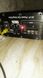
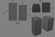
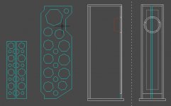
A stereo acoustic guitar tube amp in a DML briefcase format.

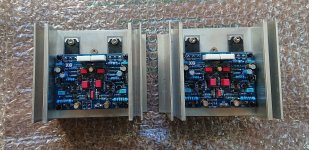
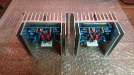
Not knowing much about tube amps, I bought some inexpensive ones to test, a stereo preamp (6J1) that I want to stack L+R for gain and overdrive (mono), and a 3+3W power amp (6P1, stereo).

My proposed circuit diagram is here:
Dropbox - AcousticGuitarAmp.png

The preamp is a 6J1 type. No questions here, simple 12 VAC supply. Now, perhaps this preamp was not a good choice (perhaps even EQ'd for a phono pickup, oops!), most guitar amps use 12AX7s tubes, whatever... any ideas or suggestions on this appreciated?). The preamp is here (got it on sale):
aassembled ac 12v 1a 6j1 preamp tube preamp amplifier board preamplifier module pre-amp headphone bile buffer stereo bass hifi x10-d Sale - Banggood.com

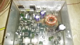
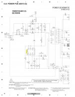
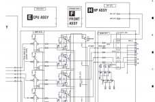
The question I have regard mostly the proper hookup of the the power amp, the classic 6P1 JCDQ-11
Many input voltages (0-230-230 and 6.3V), what appears to be options (diodes, a coil,..??) . Transformers (input and output) are mostly my issue.
Dropbox - JCDQ-11-6P1TubeAmp.png - Simplify your life
The power amp is to be found here (got it on sale):
jcdq11 tube amplifier 6n1+6p1 valve stereo amplifier board filament ac power supply + 3pcs tubes Sale - Banggood.com

Please advise. All comments, feedback, suggestions and warnings will be taken most seriously and they will be greatly appreciated. Many thanks in advance. Will share the results on INSTRUCTABLES if good.

Any hints where to get cheap reliable components will also be greatly appreciated. Such transformers appear to be quite specialized. Many thanks in advance,

Paul.
Quebec City, Canada.
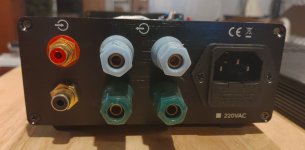
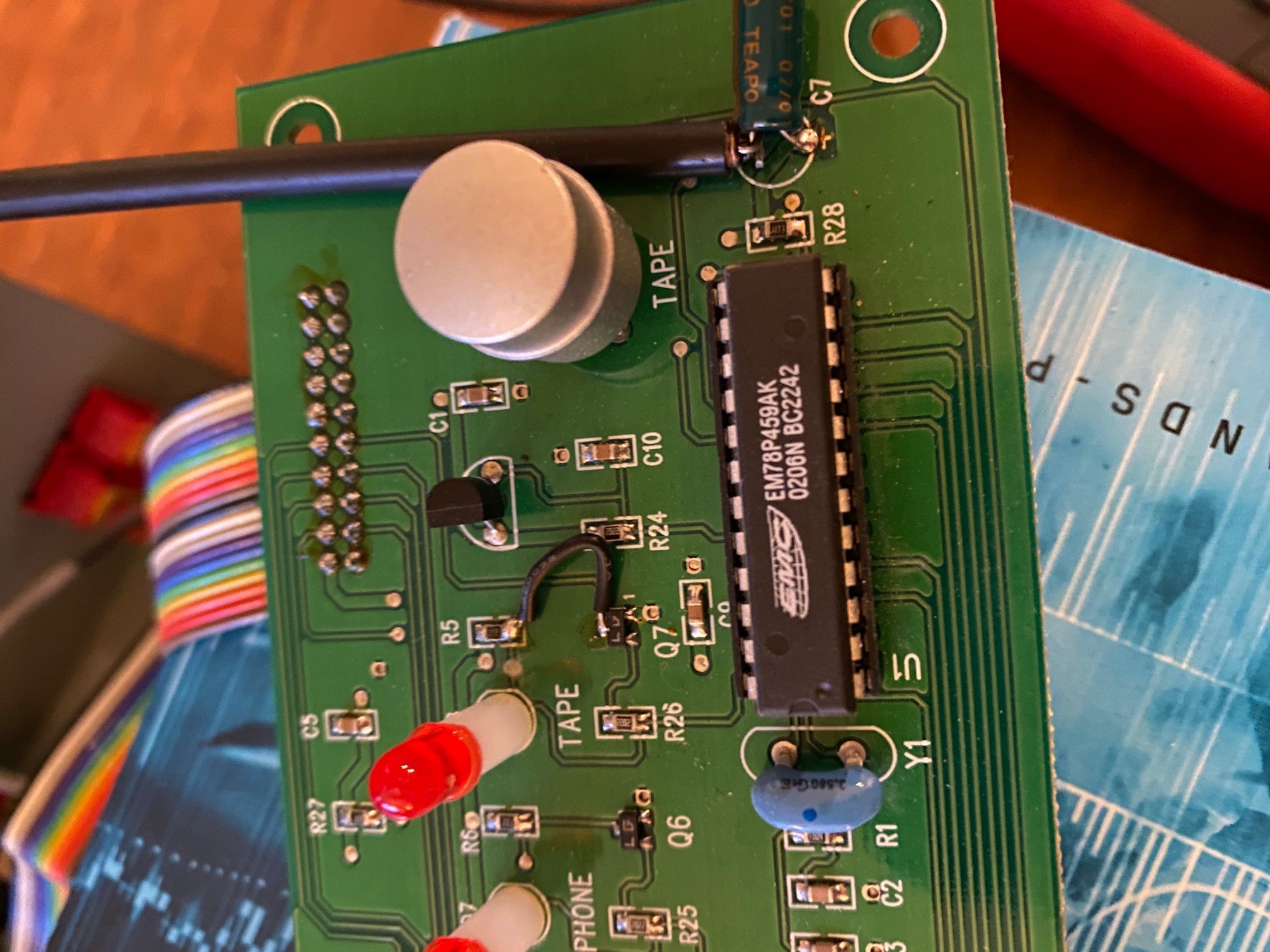
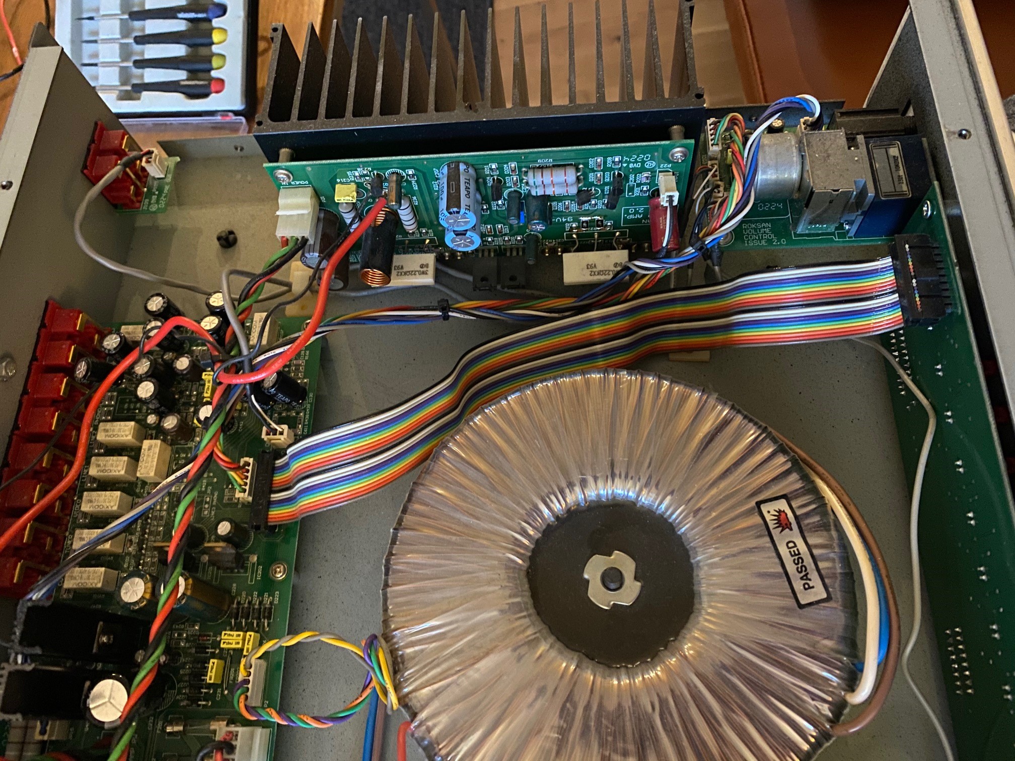
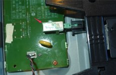
Why are Hammond SE OPTs dissed? Heavier than the competition...

I have been shopping for cheap ($100-ish) SE output transformers; One Electron, MQ Robin Hood, Edcor, andddddd...... Hammond!
I have repeatedly read that the Hammonds are nothing special sonically, and I was looking to buy One Electrons. Then I began comparing actual weights, and the Hammonds are TWICE as heavy as the One Electrons. And I've always heard and assumed that more iron=better frequency response, esp. in the bass.

Angela is carrying a newish line of Hammond SEA series trafos, supposedly improved over the old SE series?

I have found very little info on the Magnequest RH series, but I get the impression they are small and don't support much bass. I'm a bass freak, y'all! No one seems to have tried the $75 Edcors.

Any wisdom from the group? The One Electrons seemed like a sure thing until I saw they were only 6lbs. each. Maybe you can't buy "sound by the pound", but I can't help wondering.

Flower Baffle - Any Effect?

I had the chunks of cut-out from my 18's, so I decided to try a rudimentary flower baffle on an fe103en.

The Edge says I should get a nice null between 1 and 2 k, with a circular baffle. I was hoping the petals would defocus the circular edge effect.

Measuring indoors with REW (using the frequency dependent window option checked), I get much less "sharpness" in the null.
Is this because of the flower shape, or the frequency dependent window analysis preference?

I have it set on a carpeted floor with the mic 1M away, on a cushion (pic for clarity, not distance)

How can I improve my measurement certainty - besides "I should have measured the baffle when it was circular first", which I realize. Thanks!

Attachments

  • Edge-response.jpg
    Edge-response.jpg
    100.8 KB · Views: 260
  • Edge-baffle.jpg
    Edge-baffle.jpg
    57 KB · Views: 251
  • Add_FDW.jpg
    Add_FDW.jpg
    85.2 KB · Views: 248
  • DSC02669.jpg
    DSC02669.jpg
    831.1 KB · Views: 248

Theoretical question about 3 way active speakers

So I'm looking for a pair of Tri-ampable speakers to use with my DEQX
and it got me thinking. Are there any benefits to using the builtin crossovers
for each driver and just using the deqx for minimal correction/timing vs connecting it
straight to each driver?

I imagine doing more in the analog domain might sound better because well...its analog.


But I'm interested to know if anyone can chime in on this.


Regards,


Eli

I2S Problems

I am trying to interface an S/PDIF circuit based on a Crystal CS8405 S/PDIF transmitter chip with a RioReceiver network MP3 player. However, when I tap into the I2S signals feeding the DAC on the board, I get severely distorted sound from the S/PDIF output of the Crystal circuit. One channel is distortion-free until the signal reaches a certain volume, while the other channel is severely distorted. If I reset the chip, sometimes the severely distorted channel switches. I get essentially the same results regardless of the format (right justified, left justified, I2S) chosen. I have successfully used the circuit in other applications without problems. I have also tried both buffering and straight through connections. I'm convinced all the connections are correct after triple checking them. Do I need to invert one of the signals? Which one(s)? Any ideas?

Here is link to an MP3 sample of the output.

http://www.eutronix.com/media/Garbled.mp3

Thanks,
Stu

What is the maximum volt to use with this car amp?..

Guys i have a mono car amp chinese version ..a friend gave it to me after it burnt its smps MOSFETs i took it try to power it with 20± , it came on ...about it circuit it written every part of it in the board ie may be a place with Transistor A1015 then it written in the board ..its power transistor are A1695 and C4468 ..but in the board it written A1941 and C519 i think they did change those transistor before with smaller one

But my questions is how much max volt should i give it ..am currently using it with 20± it sound very good and put out ac voltage in its ouput of about 12vac thats about 36w at 4ohms load very clean and with about 18vac thats about 80w at 4ohms i think that is peak power....

Can someone tell me what is the maximum volt can i use with it...

My english is not good hope you understand

Attachments

  • IMG_20210114_073545.jpg
    IMG_20210114_073545.jpg
    331.8 KB · Views: 347
  • IMG_20210114_073536.jpg
    IMG_20210114_073536.jpg
    200 KB · Views: 205

Tweaking cabinet shape - form over function or acceptable?

Hi,

I'm in the decision making fase of building a new pair of speakers. What I'm sure of is that it will be a 'PA' style two-way with a 15" woofer and a horn loaded top. What's also a given is that it's going to be a proven design as I'm not a speaker designer, I just love building them and love woodworking.

I've selected a couple of candidates and they al have the same 'problem': too deep and plain rectangular boxes.

The changes I'm thinking of making are aimed purely at looks and a more challenging build. If that would result in sound improvements, great. It should not change the way the speaker sounds in a major way.

From what I've read, the shape of the box doesn't have a major effect on the performance if you keep the baffle and internal volume the same.

So, looking at the attached mockup, would making the baffle 10cm higher and moving the horn up by 10cm have any serious effect on sound?

The width vs depth is also closer to a 1:1 ratio (1:1.05) which is bad I read. Does curving the sides help with this or should it really be at least 1:1.2 ?

The rectangular box in the attachment is the original design, the higher, curved box is my 'design'

Thanks

Attachments

  • mockup.jpg
    mockup.jpg
    94.6 KB · Views: 409
  • calpamos.png
    calpamos.png
    468.1 KB · Views: 394

Reproduction and lack of human spirit ;)

So, I like listening to the radio (WRR - Tx's first one, about a century old).

Today, FEDEX ground brought me some of Curlymaple.Com short pieces.

I put one behind my 3" broad range (100-20kHz) drivers hanging in their shipping boxes on the back of the current pair of ~10.5" BB plywood 1/2" circles cut out with my own casual hands from the front of my ~11 cu ft WoodTiteIII sub woofer box. No screws, except to mount the Lambda 12" woofers built by the late, great Ryan right here in Texas, hear?

Dr. Bruce Edgar and Ryan, thanks to my emails, built them 12 inchers with THREE (3) magnets, each. Bruce measured them in his lab and they were smooth from 10Hz to 5 kHz, but they beamed a LOT at the higher CPS.

I am listening to them 3" hung on the backside of the circles, inside their left open shipping boxes. Those Italian speaker mfgrs know how to box their products.

FaitalPROs, if you must know. The 3" are broad range (100-20kHz) and putting a new piece of 1" maple has reduced my wife's discomfort.

There is more to enjoying Music than clever advertising.

Thank goodness 😉

@1

First Build: Pensil P11

Hello Everyone,

Recently I stumbled on an ad for the Wrensilva's audio consoles, and the idea of making a similar piece stuck in my head. I'm quite competent making cabinets and have machinery and some materials available. On the other side, I'm an utter neophyte regarding audio; so I started lurking here.

Since I know next to nothing about electronics I opted to go with a full range design. I got a good deal on a pair of Pluvia 11s and so, I have the drivers in my hands. I later opted to make a pair of speakers instead of the audio console, since don't really have room for it.

I usually listen from Spotify via Bluetooth, have a number of classical music CD's which I listen from time to time too. I bought an Onkyo TX8220 to power the speakers, probably arriving later this week. Not a conossieur, as you may notice.

Initially I was thinking into making a folded horn design, but found a review of the Pensil 11 on HiFi Pig that changed my mind. Also it looks easier to build.

Now regarding the build, I'm going to list some hard constraints, some good things, and some questions in no particular order. Would appreciate your input.

  • First of all, I'm using the Pensil A11/P11 plan as base for this build: https://frugal-phile.com/boxlib/pensils/PensilA11-P11.pdf
  • Something not good: I don't have a source for good plywood. On the other hand I have plenty of MDF. I made a preliminar design using 15 mm MDF keeping the internal dimensions untouched. Could use other thicknesses, but I'm used to work with 15 mm and have more finishing options with it.
  • Another not so good thing: I have no clamps. I will "press" the panels using Minifix fittings while the glue cures. I've done that before with furniture, let's see how it works on speakers.
  • Something positive: I have plenty of dampening materials: delcron, felt, PU foam, eggshell foam, etc. Also, have access to some well tooled CNC routers.
  • A question: If not using internal bracing, how do you keep the fiber stuffing from going to the bottom?
  • Regarding the terminal cup: Is there a prefered place to put it or it doesn't matter as much?
Thanks a lot.


Rodrigo

Attachments

  • Pensil 11 CAD Preliminar.jpg
    Pensil 11 CAD Preliminar.jpg
    66 KB · Views: 1,770

Op-amp decoupling - best practice?

Hi folks.

I was wondering if there's any definitive rule on which approach is best in regards to op-amp bypasses: a single 100nF cap across the + and - pins, OR a 100nF cap from + to ground, and another from - to ground?

I have read so many conflicting opinions on this over the past month I don't know what to think. Some think mounting the cap across the pins does nothing. Others believe coupling to ground can inject noise into the op-amp. A few differing opinions I've read recently include:

From Rod Elliot:

Coupling Capacitors

"High speed opamps must have good bypassing. Most of the time, this will be between the power supplies, avoiding the earth (ground) circuit completely. A normal opamp has no knowledge of earth, ground planes or anything else earth related. It is only interested in the voltages present at its two inputs, and when used in linear mode will attempt to make them the same voltage."

From DaDa (Quad modification web forum & shop):

Quad 34 and DaDa's new LME op-amp upgrades

"My experiences with decoupling of LME's are the opposite, the oscillation will not go away with ceramics between the plus and the minus. Only when decoupled both supplies (from + & - to ground) the oscillation is cured. The oscillation of this kind is a LF oscillation, a loud, in most cases 100Hz, based noise is there. Although I believe you, my next remark will contradict this, I doubt if you really can hear the placement of a decoupling cap."

And from Douglass Self:

http://www.eetimes.com/document.asp?doc_id=1278963

"The essential requirement is that the positive and negative rails should be decoupled with a 100 nF capacitor between them, at a distance of not more than a few millimeters from the op-amp; normally one such capacitor is fitted per package as close to it as possible.

It is not necessary, and often not desirable, to have two capacitors going to ground; every capacitor between a supply rail and ground carries the risk of injecting rail noise into the ground."

In my case I'm using a Quad 34 (which has a virtual ground) which has had most of the coupling caps removed, and different op-amps tried. OPA134s 'sound' very natural/organic to me, and don't require any decoupling caps to operate well in this circuit. Trying LME49710/20s - a superior op-amp, on paper - and it oscillated. So following DaDa's advice I bypassed from + to ground, and - to ground on one of the op-amps which cured the oscillation hum. But I was left with the impression they weren't performing at their best - sounded a little too 'lean' and boring?! I had to remove them after a week as I wasn't enjoying the music. I was wondering if the Quad 34s virtual ground in its PSU supply was injecting a little noise into the LMEs via the op-amp decoupling caps perhaps?

Any thoughts about this would be welcome to this 'non expert' 😉

Cheers,

John.

Musical Fidelity A1 power amplifier clone boards

Two MF1 Power amplifier boards, new, assembled and tested, on heatsinks. As on original MF1 schematics, good material, Toshiba 1941/5198 output transistors. 20W/8 Ohms, adjustable to A-Class. Have assembled a few amps with such modules and IMHO they sound very nice.

Dimension of one modul 125x100x80mm.

Price 60€ for pair + shipping.

Regards

Attachments

  • m1.jpg
    m1.jpg
    428.7 KB · Views: 821
  • m2.jpg
    m2.jpg
    823.1 KB · Views: 720
  • m3.jpg
    m3.jpg
    303.7 KB · Views: 682
  • m5.jpg
    m5.jpg
    566.7 KB · Views: 797
  • mf-a1.gif
    mf-a1.gif
    15.5 KB · Views: 779

Marantz CD6000 power switch

Guys, I was damping and putting bypass caps on my CD6000 and must have jammed the power switch that connects to the long plastic arm that turns on the unit.
If I hold the power button on the front of the unit all the way in, it comes on, if I release the pressure at all it turns off.
Can the switch in the box be repaired? If so how?
If I need to replace it does anyone know the part number and where I might find one?
See below for the switch box.
Thanks, Nut

Attachments

  • Switch.jpg
    Switch.jpg
    135 KB · Views: 77

Help with PSU in McIntosh MX113

I have a McIntosh MX113 that has been sitting on my shelf for several years. It was not working when I bought it. The seller indicated that it had a PSU problem. Indeed it did. The main transistor was blown and several resisters were either burned or burned completely through (open). Attached is the schematic. I have replaced all the resistors that were burned or destroyed (R209, burned thru; R208, burned and changed value; R222, burned thru). I replaced the original transistor Q202 (originally 2N3738) with a TIP50. The zener, D207 was broken so I replaced it with a 1N5946B (originally 1N982B).

I have disconnected all loads, including the center channel driver (right side of the schematic). I'm getting the following voltages at Q202:

C - 182 (should be 96)
B - 72 (should be 76)
E - 56 (should be 75)

This uses 2 segmented can capacitors and I have not replaced those (yet).

This is obviously a simple PSU but it has me baffled. I'd appreciate any suggestions about what to look at.

Thanks.

Attachments

Projects by fanatics, for fanatics
Get answers and advice for everyone wanting to learn the art of audio.
Join the Community
507,862
Members
7,891,228
Messages

Filter

Forum Statistics

Threads
406,389
Messages
7,891,228
Members
507,862
Latest member
Gio_muc