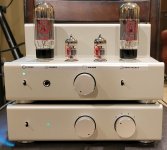
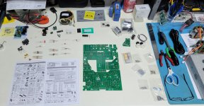
An illustrated guide to building the Aleph J
This is a guide to building the Nelson Pass / Firstwatt 'Aleph J' amplifier.
A few links to start off -
Aleph J Manual (From firstwatt.com)
http://firstwatt.com/pdf/prod_aj_man.pdf
Amplifier PCB (From DIYaudio)
Aleph J (2 PCBs included, which makes 2 channels) - Circuit Boards
Discussion thread -
Aleph J for Universal Mounting Spec - diyAudio
Bill of Materials (BOM) -
diyAudio
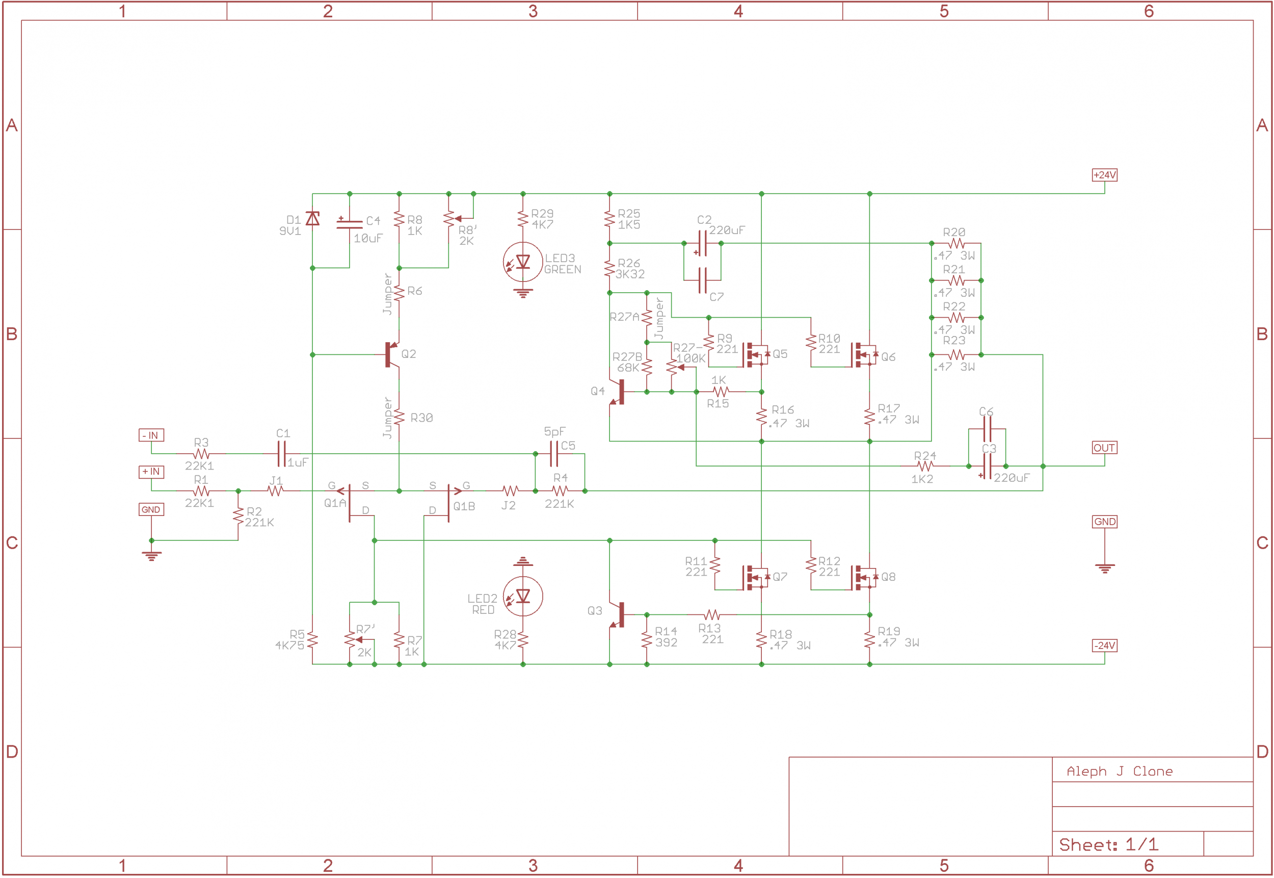
Schematic -
Ok!
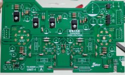
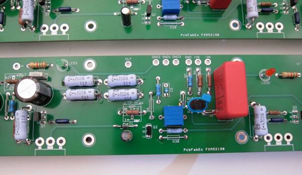
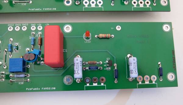
The bulk of this guide is going to show the green PCB, which were proof-of-concept prototypes. The boards worked great and we needed to make very minor changes to the production boards, which are blue. There is effectively no difference between the prototype and production boards. Also worth note, the photos of the PCB will be from two different builds, mine (6L6), and Grimberg's. There are no significant differences in how the PCB was stuffed or utilized. I think Grimberg did a prettier job stuffing the PCB than I did.
🙂
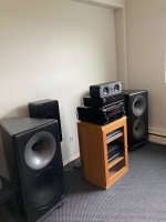
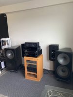
Also, this build will show a 5U 'Big Amp Chassis' from the DIYaudio store. (Because that's what I have on hand.) The Aleph J can be made into the 4U 'Jack of all Chassis', everything will fit and the heatsinks are (just) big enough. All the specifics surrounding the 'premium' chassis (back panel, perforated base, pre-drilled heatsink, etc…) are functionally identical, the differences between the 4U and 5U are mainly just size. Regardless of the chassis you use, this amp does get quite hot, and good ventilation will be required around the entire chassis.
On to the guide.
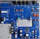
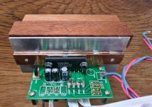
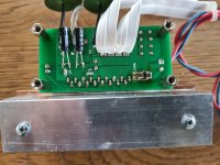
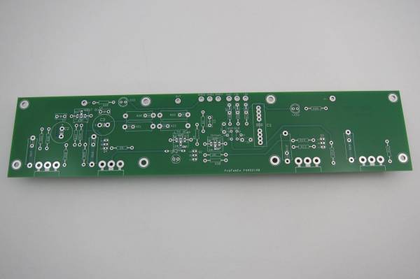
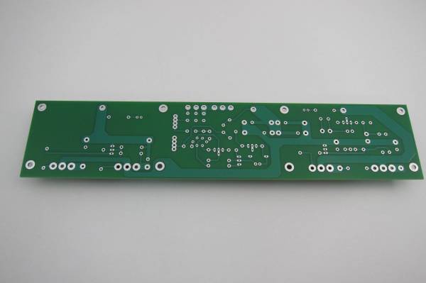
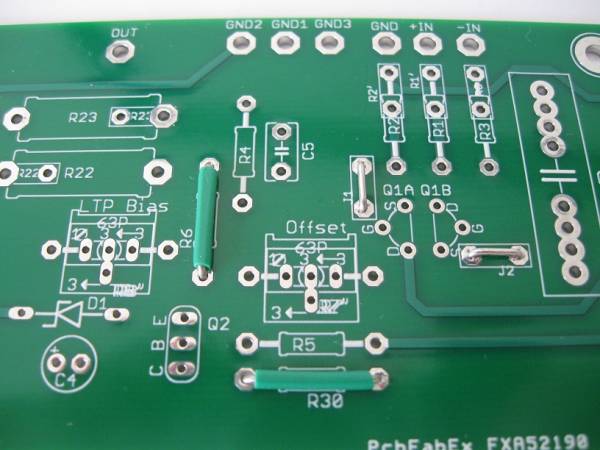
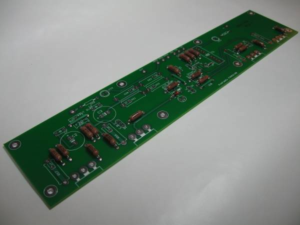
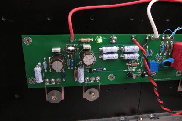
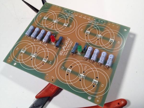
Here is the PCB. It's a great layout, please thank member Didiet78 for his work making this.
😀
Front
Back
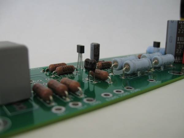
Stuffing the PCB
The normal order of operations is to do the little things first and place the bigger things as you proceed.
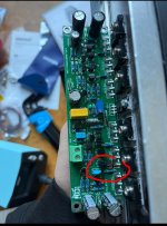
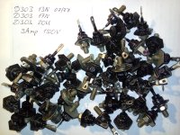
This PCB has 4 connections that are normally going to be jumpers. (R6, R30, J1, J2) You can see them here. These connections can be jumpered with little bits of wire or cut-off resistor leads, your choice.
These 4 pads are there in case you need to add some resistors in case of oscillation, which may happen to some builds. It's rare, but if you need it, there is place on the PCB to add some compensating devices.
R27. SEE TEXT
Let's talk about this - as it is somewhat confusing.
There are 3 places for R27 on this PCB. The first is the pad next to the cap C2. (in the above photo it is empty) I suggest making that one a jumper.
Where the jumper is placed in the photo should be open, and under the green insulation you will find the place for a pot.
SO - place a 100K pot where the pot will fit and jumper the vertical 'R27'. Set the pot to 68K before you turn the amp on the first time.
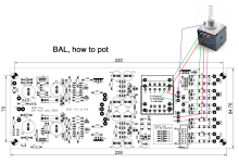
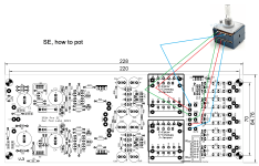
Here you can see how the pads for the pot are arranged - (underneath where it says "LTP Bias" and similarly under "offset")
The small oval pads are where the pot connects. The larger round pads outboard of the silkscreen are for a resistor if you choose to put it there in lieu of the pot, or can be used to measure across the pot in circuit. Cool, huh?
Also, it does not matter which of the center pads you use - some pots have all three pins in a row, some have the center pin offset. Either type will be fine.
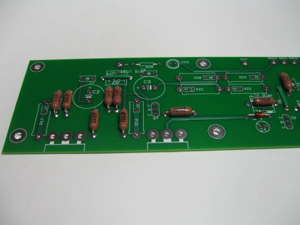
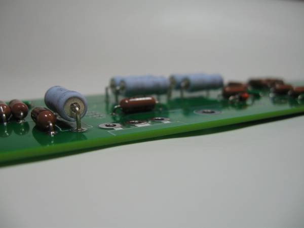
Add the resistors. Shown here are big-bodied Dale RN60. If these fit, and they do, most other resistors will as well. Use whatever parts suit your fancy.
Now add the bigger (3Watt) resistors. It's a good idea to leave some room between the PCB and the body to let air circulate. As shown here -
The best advice I can give you is this -
measure every resistor before inserting into the board.
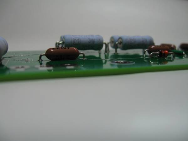
Continue on with caps and the small transistors
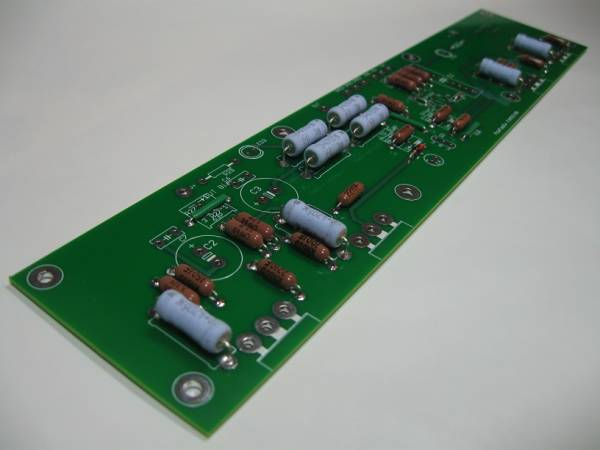
Eventually the board will look something like this -
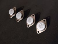
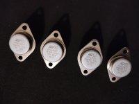
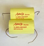
For reference, know that the Power Mosfets (obviously not mounted yet…) on the Left side of the PCB, near the electrolytic capacitors are for the Constant Current Source, and the Mosfets on the Right side, closer to the red input film capacitor, are the Outputs.
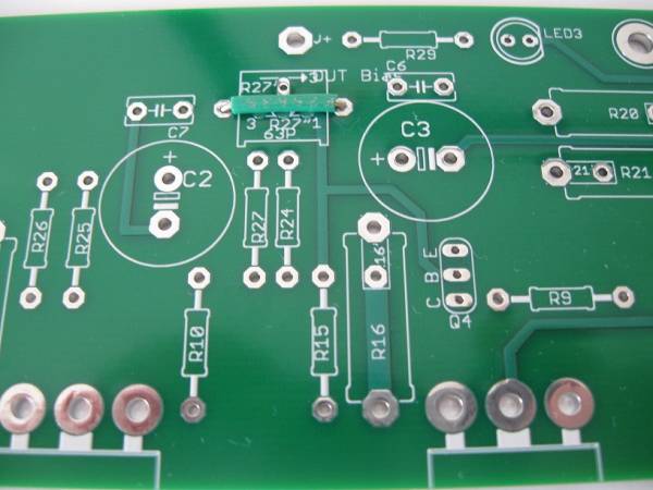
Note that in this photo, the vertical R27 is jumpered, and there is a 68K resistor in the horizontal spot. I later replaced the resistor with a pot.
Here is the pot in that position. I used a single-turn because I had one on hand... I strongly suggest multi-turn pots on all of these projects.
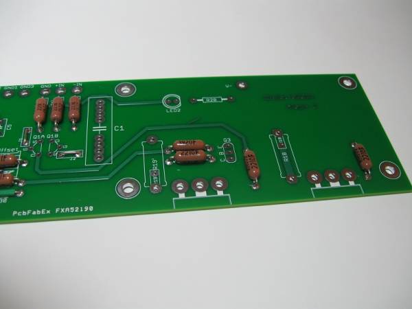
Yes, have my LED colors reversed. The V+ should be red. I've even had it marked backwards in the schematic. Lol.
🙂 You could make them all blue, this is a Pass amp, after all…
🙂
The LED on the PCB are there to show that you have the rails connected and the amp PCB is getting voltage. If you want to extend the leads on one of these and make it a panel light, feel free.
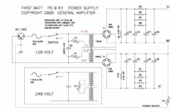
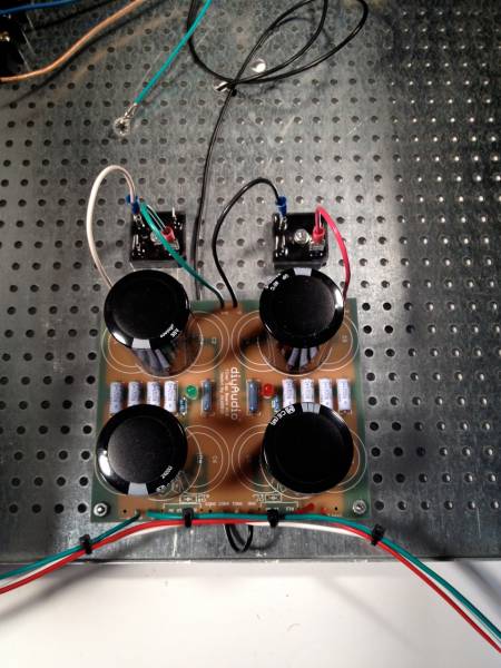
Power Supply
The power supply for the Aleph J is going to follow the basic pattern of the Pass/Firstwatt DIY amplifiers. Please look at the following schematic --
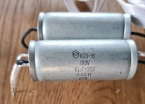
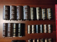
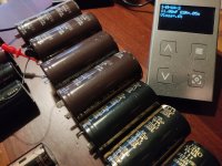
The basic topology is this. 18+18V transformer, of at least 300VA, CRC filter with 8 15,000uF 25V capacitors and 8 (4 per rail) 0.47ohm 3W resistors.
May you use a transformer with more VA? Yes, of course.
May you use larger Capacitors? (more uF) Yes.
May you use capacitors with a different voltage rating? Yes, as long as you have 25V
or more. (25V, 50V, etc…)
Remember that the factory Firstwatt amps use 300VA transformers and (8) 15,000uF 25V caps. If that's good enough for Papa… It should be good enough for you. But almost everybody makes it bigger. No problem at all. It's easy, so you might as well...
🙂
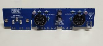
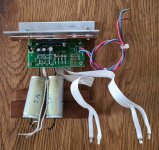
In this build I am using the old (smaller) DIYaudio PSU board. This particular one has no blue soldermask on the top of the PCB. It is otherwise identical. The section for the discrete diode bridges has been snapped off.
IMG_0822 - My Photo Gallery
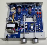
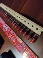
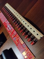
Here shown with the Filter resistors (0.47Ohm, 3W, light blue), the Bleeder (2.2Kohm, 3W, dark blue) and LEDs.
For some reason I can get the LED color correct on this PCB… Red for V+, Green for V-
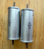
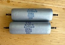
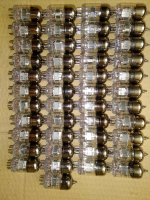
The PCB can accept (8) caps with 10mm lead spacing and 30mm diameter, or (4) of 35mm diameter. These are 33,000uF 35V Panasonic T-UP series caps.
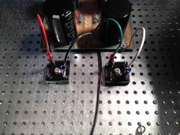
I prefer to use diode bridges in these monolithic blocks.
Bridge connections.
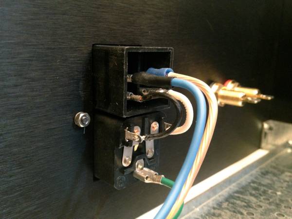
IEC inlet.
120V AC wiring shown - this is the primaries of the transformer. AC will attach to the center terminals.
You are free to comment or question.
😀