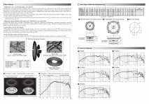
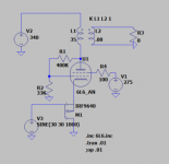
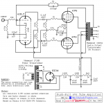
I set up a very fast pulse driver to investigate high-Vg1 operation.
Approximate circuit. There are two pins for each grid; both are connected. G2 was tested with direct shorts to ground, and 47 ohm resistors each pin, without much difference. Heater (not shown) is bypassed at the base with a pair of 10nF ceramics, then a twisted pair with ferrite beads comes back to the breadboard.
What's that heresy on the left? When you overvoltage a BJT, it draws current exponentially, much like a zener diode does. It happens to depend upon base connection. When base is open, you get a limit of Vceo (measured C-E). When emitter is open, Vcbo (measured C-B, and is higher). It stands to reason, there's a region connecting these, for intermediate values of base/emitter current: this is where R2 comes into play.
If you've ever biased a zener diode at light currents and measured it, you've probably noticed it has a very noisy level, that seems to act like rising ramps and random height discharges. This is avalanche breakdown, the avalanche being multiplied randomly by charges accelerated by the high voltage, impacting atoms or impurities in the junction. Well, BJTs exhibit the same behavior, but in this region of operation, it's turned up to eleven: the avalanche can go all the way to zero. And it happens very quickly: it can take but a fraction of a nanosecond! (2N2369 is the classic type used for this, e.g. Linear Technology AN-47, Jim Williams' favorite pulse generator circuit. There are also purpose-tested parts available, e.g. FMMT417TD -- pricey, but you pay for testing, parts that are reliable in this otherwise undocumented operating mode.)
So, simply read this as a fast switch pulling the left end of C2 up to GND momentarily. Much like a gas discharge tube. The '3904 breaks down around 100-120V.
Mind, it's not an ideal switch; internal resistance is still present. For the '3904, this is about 10-20 ohms, not great. It's just what's handy.
Anyway, this pulse is coupled through C2 into the grid, which is biased and terminated. R4-L1 discharges the grid relatively quickly after a pulse (along with C2 and Cin, they set the pulse duration). C- is typically -20V or so, enough to keep the tube in cutoff at 2kV.
C1 is a fairly large ceramic disc cap, and R3 is a TO-220 thin-film resistor -- may be noteworthy because their parasitics aren't exactly negligible here.
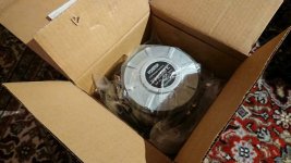
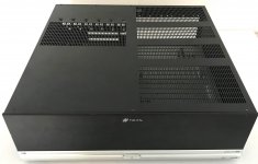
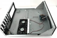
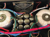
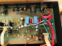
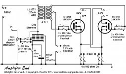
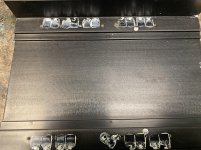
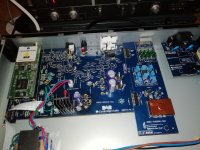
Photo:
Breadboard for convenience. Left module is a 12:140V isolated supply, positive grounded. Middle is a 2000V modest-current supply (up to 10mA or so). (You maybe can't tell in the photo, but the 100k carbon-comp plate resistor is swollen from running it at zero bias a little too long. So, it has at least enough power to do that.) Red and blue wire coming up from the bottom are a ballast resistor for the heater; bench supply is 12V, and it's just dropped down to get a nice 6.3V here.
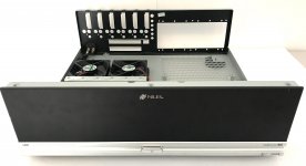
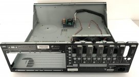
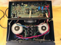
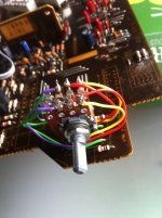
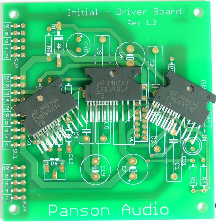
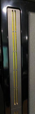
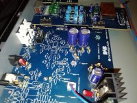
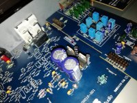
And the test circuit / module on the right. The avalanche pulser is in the bottom front, Manhattan style with SMTs and axials. Two red wires snake up the riser board, connecting to both grid pins. Tube is contained in the cage (shielding to keep plate voltage contained -- these waveforms are like weak ESD, the fast edges get everywhere). A PCB socket provides connection.
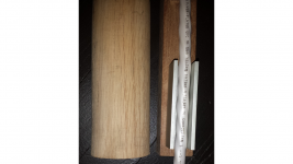
Sitting on top of the test circuit, a hand made 100x probe. It's... not great at these edge rates, but it seems to be doing alright here.
I built it this way to get minimum distance, stray inductance, whatever, to the base of the tube. I can't do anything about what's inside it (in particular, the thin wire links to electrodes, and the overall height of the electrode structure), and I think that's a big part of the ringing waveform. Basically, to see what can be done, within those limitations.
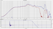
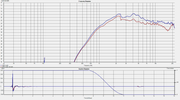
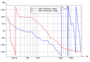
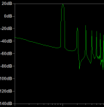
On to the most important part, the waveform:
Ch1: 100x probe, across R3.
Ch3: 10x probe, G1 voltage.
Bias has been adjusted up here, for the biggest possible pulse. So, that's about 2A peak plate current, and 60V peak grid voltage.
Not shown: the cathode voltage shows a bit over 10V peak, or about 4.5A. Presumably the difference (2.5A) is grid current.
(The beam plates (G2, with 2 x 47 ohm resistors to GND) also show a significant peak of -15.6V, followed by a rebound to +9V, then lumpy decay. This seems in the right ballpark for Cg2a ~ 10pF.)
I'm a bit surprised the peak current isn't higher, or, the plate current isn't; limited by the, hFE so to speak, which seems to be pretty poor at this point.
Also wonder how it varies with pulse width. Radar modulator tubes are rated for pulses of microseconds, sweeps tens of microseconds; maybe there just isn't much space charge available on a nanosecond basis?
Tim