Hi folks
I need to build a phono preamp to replace my NAD unit that died on me.
A JFET design appeals, but I don't have any 2SK170s left, I used the few I had to build a B1 buffer.
However, I do have quite a few BF862s that I soldered onto mini PCBs.
So, what phono preamp design is suitable for using BF862s rather than 2SK170s?
Chances are you will only have to change the supply voltage, and maybe not even that. The BF862 can handle less voltage than the 2SK170 and it has a higher transconductance, but otherwise they are rather similar.
What voltage would you suggest - 18v?
How important to the sound quality is the choice of caps for that circuit? I see most of the builds of it are using Russian PIO military ones. I have all the values needed in the form of poly caps, mostly WIMA. Maybe I'll build one using the caps I have and see how it sounds, I can always buy some more exotic caps if it's not so great with more mundane caps.
How important to the sound quality is the choice of caps for that circuit? I see most of the builds of it are using Russian PIO military ones. I have all the values needed in the form of poly caps, mostly WIMA. Maybe I'll build one using the caps I have and see how it sounds, I can always buy some more exotic caps if it's not so great with more mundane caps.
Assuming your JFETs are for an input stage LTP, they would need to be matched to live up to their reputation which is probably more important than whatever transistor type or grade takes your fancy. LSK389 has the practical benefit of acceptable, often excellent matching of the pair and can still be cheaper to use than testing and trying to get a match multiple discrete devices.
Parameter spreads are much wider than for BJTs, even from adjacent devices on the same silicon wafer. That doesn't mean you can't use them in other circuits that don't require matched semis but it does rather spoil your game when you need to construct and use a JFET test jig to select a match from only a small number of transistors and likely can't find an acceptable match between any.
The high demand and very high prices for these obsolete JFETs makes it difficult to use them as required by the best designs so I choose BJTs and perhaps the occasional small-signal MOSFET, wherever possible now. Still, if you make a jig, do get lucky and find a match or don't even need a match, there's every reason to go ahead with what's in the parts bin.
As a suggestion, you might search threads here by wrenchone who has designed and experimented with many JFET preamp ideas and semis over many years here - adding some innovative designs, plus plenty of informative and useful comments to think about. In any case, check the Line-Level forum here for preamps and other small-signal projects - it's actually where preamps matters should be posted.
Hi Ian,
Mike Renardson has an RIAA design using a BF862 as the input device:
Phono Pre-amp Circuit
A lot interesting reading on his site, as well, plus Mike also posts here occasionally.
Paul
Mike Renardson has an RIAA design using a BF862 as the input device:
Phono Pre-amp Circuit
A lot interesting reading on his site, as well, plus Mike also posts here occasionally.
Paul
Like I said, I have quite a lot of BF862s so I can make some matched pairs I think, the BF862 I known to be pretty consistent in parameters, so it shouldn't be too difficult.
Does anyone know if PCBs for the Boozhound or a similar variant of the Le Pacific are available for sale anywhere? I can make them using perf board of course, but I'd prefer a proper PCB if possible.
Does anyone know if PCBs for the Boozhound or a similar variant of the Le Pacific are available for sale anywhere? I can make them using perf board of course, but I'd prefer a proper PCB if possible.
What voltage would you suggest - 18v?
It's not as easy as I thought it would be...
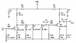
The drain voltage has to be high enough to saturate the JFETs, yet small enough not to cause excessive gate leakage. Looking at the datasheet, that means a momentary drain voltage in the 2 V to 12 V range. For maximum signal handling, the drain bias voltage has to be somewhere in the centre of this range, so about 7 V.
Looking at figure 7 of the datasheet, a 50 ohm source resistor will result in a drain current of about 6.5 mA for a typical BF862. That will cause a drop of 20.6 V across the 3.16 kohm + 10 ohm drain resistors. Adding that to the desired 7 V, you end up at a supply voltage of 27.6 V.
Looking at the minimum current curve of figure 7, the minimum drain current with a 50 ohm source resistor is about 4 mA. That causes a drop of 12.68 V, so the drain voltage at 27.6 V supply then becomes 14.92 V, which is rather high. The maximum current is around 9 mA, drop 28.53 V, which means the JFET actually goes out of saturation.
In any case, supply voltages below 20 V are desirable to make sure you don't exceed the 20 V maximum rating when the signals are large (when playing scratches, for example). Your 18 V would therefore be better than 27.6 V.
With 18 V supply, you would need an 11 V drop across the drain resistors to end up with 7 V drain voltage. The drain current then has to be around 3.47 mA. Source resistors of 130 ohm result in about 3.47 mA for a typical BF862, 2 to 4.5 mA for extreme BF862s, drain voltage at 18 V then in the 3.7 V to 11.7 V. The gain will unfortunately be about 10 dB lower than in the original design, unless you decouple a part of the source resistors.
How important to the sound quality is the choice of caps for that circuit? I see most of the builds of it are using Russian PIO military ones. I have all the values needed in the form of poly caps, mostly WIMA. Maybe I'll build one using the caps I have and see how it sounds, I can always buy some more exotic caps if it's not so great with more mundane caps.
Whatever you do, don't use ceramic class 2 capacitors, nor capacitors with a large tolerance. I would normally use 1 % tolerance polystyrene or polypropylene capacitors in a RIAA correction network.
I've ordered the AM Audio PCBs of their Boozhound as I already have the Russian PIO caps it uses, leftovers from the B1 Buffer I built using Russian PIO caps. I'll be placing the phono preamp in the same chassis with the B1 so it's nice to have the same caps on both.
I don't understand a thing MarcelvdG said, but I have a B1, Pocket Class A (PCA) headamp and the Aksa Lender preamp - all built using the beloved BF862s. Almost built an ACA with them too. My preamp is running on 18.2V rails, which according to xrk971 is the sweetspot for this jfet.
That's interesting to know, cheers. Did you match your BF862s? If so, how difficult was it to find matches?
Yes, I matched them and found two matched pairs within 0.1 or 0.2mA idss from 20 pieces if I remember correctly.
You have them soldered onto mini pcbs? Should not be too difficult. I made my own tiny jig with a 9v battery, resistor and a toggle switch. Had to hold the fets in place with a tweezer (non conductive) using magnifying glasses, then flip the toggle switch and let the readings settle down. I enjoyed it.
I have soldered about half of what I have onto PCBs, not a fun task!
I shall have to make a testing rig, I might have to pick your brains for guidance when I do.
I shall have to make a testing rig, I might have to pick your brains for guidance when I do.
- Home
- Source & Line
- Analogue Source
- Phono preamp using BF862?