Load resistors for LTP when using CCS tail

Does the standard rule of thumb for plate load resistors (~2x the plate resistance) still hold true when using a CCS tail?

I ask the question as most of the reading I've done tends to gloss over on the exact details of designing a LTP with a CCS. Most writers say to use one for best balance between outputs, but then proceed to explain how to design one for a guitar amp using a smallish tail resistor.

I've got one on my bench that is working fine, but the values of my plate loads were arrived by looking at other designs and a little trial and error rather than a general understanding of the theory.

E55L Parafeed Spud Design - Your Thoughts

I am considering an E55L parafeed spud amplifier later this year. I've been doing this tube DIY thing for a little over a year now, want to see if I am overlooking anything and get some feedback.

Here is the draft schematic and then some commentary. Note that some part values are stand-ins.

E55L Spud.png

Rather than a plate choke, I would use a cascode CCS load on the E55L. I have a spare Sowter 325VAC 161mA mains transformer with the appropriate voltage to cover the full peak-to-peak E55L plate swing and headroom of the CCS.

I would like to use a 1:2 SUT on the input to reach full output of the E55L with a 2Vrms input.

My mains transformer has three 6.3VAC secondaries. I was thinking of using a voltage doubler on one and going fixed bias since the E55L will only need around -7V on the grid.

The other two 6.3VAC secondaries would be used for the E55L heaters and a tube rectifier.

For the power supply, had thought to use 5V4G or GZ37 for soft start. The Vdrop of the rectifier will help chop off some excess voltage and spare the CCS some heat. Given the PSRR of the CCS, a simple passive CLC supply could be used.

For output transformers, I have swapped emails with Jack and Electra-Print a few times, would like to try his stuff out. I had thought to order a pair of multi-tap 2.5K parafeed transformers with 8, 32, 120, and 300ohm secondaries. This amplifier could do around 2W into 8ohms, so good for a flea-watt speaker setup and gobs of power for headphones.

Thanks for your input 😀

Ground loops within a single chassis?

I'm planning to build an enclosure with the following things in it:

- Power entry module (PEM) with fusing and internal EMI filter
- Ground loop breaker (GLB) consisting of bridge rectifier, resistor(s), capacitor
- Connex SMPS800RS with +48 VDC and 0 VDC outputs (the 0 VDC output appears to be isolated from input power ground although I'm not 100% sure)
- Some sort of +7.5 VDC SMPS whose 0 VDC output is fully isolated from ground
- 2x TPA3255EVM and 2x some other TPA3255 amp boards for 8 amp channels altogether, which have plated mounting holes connected to their incoming power ground/common
- freeDSP Aurora which has plated mounting holes connected to its incoming power ground/common

Diagram to follow, but essentially the way it will be connected is as follows:

- Mains power from the PEM is connected to both power supplies. The mains ground is tied to chassis using a grounding bolt (the metal body of the PEM is also contacting the chassis directly)
- The GLB is fed from the grounding bolt and has "output" tied to the SMPS800RS input power ground and USB connector/cable ground
- The amp boards are fed from the SMPS800RS outputs.
- The power for the Aurora is from the +7.5 VDC SMPS outputs.
- The audio input for the Aurora is via USB connector from a PC.
- The Aurora will transmit audio out via balanced outputs to all 8 amp channels, probably (small chance of single-ended connections)
- The mounting holes of all amp boards and Aurora are isolated from chassis (i.e. not connected to ground).
- The only conductors electrically bonded to chassis are:
-- Incoming mains ground
-- Grounding bolt for safety - which feeds the input of the GLB
- All wiring is contained within the enclosure, with the exception of mains power cable, USB cable, and speaker cables

Some questions:

1) Will I have a ground loop between the two power supplies, or their downstream devices, because neither of their outputs are referenced to ground? Again, not 100% sure that the SMPS800RS output is fully isolated from ground but I get what seems to be an open connection when I try to check resistance between 0 VDC output (marked "GND", surprisingly, on the PCB) and the input ground terminal.

2) From a ground loop standpoint, does it matter if the audio output from the Aurora is single-ended or balanced to the amp boards?

3) Should I bond the mounting hole(s), or some other connection/terminal/reference intended to be grounded, of the amp boards to the output of the GLB so that the amps don't float?

4) Should I bond the mounting hole(s), or some other connection/terminal/reference intended to be grounded, of the Aurora to the output of the GLB? The USB connection prevents the Aurora from floating, I think.

5) What else should I do to mitigate ground loops in this fully-self-enclosed system?

Question about relays

Hello I am new here. I am not sure if I am posting this in the right place.
I have a Sherbourn 5 channel amp. The relays have started to give me problems. I went on the web to try and find replacements but cant find the same ones. My amp uses 15 amps relay and I found ones that are only 10 amps. Do you think these relays could work? I have included pictures of both relays. The first one is from my amp, the second one are the ones I found on ebay.

Attachments

  • WhatsApp Image 2021-02-27 at 11.56.24 PM.jpeg
    WhatsApp Image 2021-02-27 at 11.56.24 PM.jpeg
    148.5 KB · Views: 232
  • s-l1600.jpg
    s-l1600.jpg
    133 KB · Views: 237

Marshall Reverb 75 (5275) - Hum issues

Hi everybody,

looking for advice from someone which has more experience with guitar amplifiers (diffent manufacturer build approaches and motivations like in hifi).

In general the noise floor is higher, some buzz hum/level is normal (various guitar pickups, sensitive speakers, chassis shielding standards are lower = the top cover is often wood frame).

The particular amplifier I am trying to fix (solid state Marshall 5275 from 80's) is humming/buzzing more like my previous guitar amplifiers so I am still not 100 percent sure it is normal, but I have found numerous mentions that Marshalls from that era are noisy and they did not bother with hum because it does not matter at band level volume.

This unit is freshly after service where all the usual culprits where handled:

- cracked solder joints checked
- all potentiometers cleaned
- bolts are chacked and fastened
- pcb connections to chassis, checked and cleaned
- input, foot switch, effects loop, external cabinet jack sockets are cleaned
- all electrolytic caps replaced
- all coupling tantualum caps replaced (with bipolar electrolytics)
- preamp power supply zeners replaced
- main rectifier bridge replaced
- factory mods and differences between schematic and amp were reviewed
- opamps were checked and put into socket
- infamous channel switching IC CA3046 was checked

The hum buzz level is exactly like it was before the service. I have measured it with REW on idle via headphones output. Attaching it together with schematics.

The most dominant hum frequencies are basic 50Hz and 3rd harmonic 150Hz.

Transformer itself has mechanical hum and there is also full size spring reverb tank at the bottom.

Any ideas and hints are welcomed.

Thank you.

Attachments

  • Untitled.jpg
    Untitled.jpg
    201.9 KB · Views: 383
  • 5275.gif
    5275.gif
    184.5 KB · Views: 536

Tape head amplification circuit

I would like information on how I could amplify the low level signal from a tape playback head. I realize that I could take an existing player apart however the amount of mechanical parts used to operate the player would probably over complicate things for my purpose. Is a preamp necessary or could one go directly to an amplifier? I do not need audiophile quality. What are the various leads off the back of the head for. Some have two and others have four.

Thanks in advance for any input.

Jason

For Sale Pass ACA (UK based)

Here before ebay and others,
A long over due clear out of my amp collection I've built up over the past few years and sadly this one is another which has to go. The superb DIYaudio Pass ACA 4watt amp.

49867180802_aa42f6c975_k_d.jpg


49867181132_8a53eafd46_k_d.jpg


49867180502_2a2abfa9af_k_d.jpg


49867180207_48af4e8b24_k_d.jpg


49866869956_669cb6e0dd_k_d.jpg


It has been upgraded with various tweaks (premium parts) as kindly outlined and posted by TungstenAudio, well worth the extra effort.

£225 + shipping at cost or collection by arrangement..

TIA

New Williamson 5-20 40W Build

My Maplin Millenium clone didn't work so I'm going to salvage the expensive components for this Williamson 5-20.

It uses an E-Bay PCB from R-Sound.

I'm salvaging the following components:-

4 x EL34, 2 x EF86, 2 x ECC83

2 x Hammond 1650H 6.6K OPTs

240V / 350V 250VA transformer (actually 2 transformers working together)
240V / 6V 50VA transformer

The B+ might be a bit high. I'm aiming to reduce it with a CRC arrangement. Solid State rectification into 220uF then 200R followed by 600uF.

Attachments

  • s-l1600.jpg
    s-l1600.jpg
    136.8 KB · Views: 391

GK-1 Post toddler cupboard dive

So my kids are now at an age where hopefully they will stop prodding speaker cones therefore I've dug out my gk1 and aksa 55N.

Hugh was already gracious enough to forward me all the old paperwork I had misplaced and I have somehow got the remote working.

Next issue is the sub outputs appear dead.

When I connect the subwoofer to the regular pre-outs, it works fine. Before I dig out Allen keys to open the case can anyone provide advice on where I should start looking for the issue.

Thanks all and hope all you wonderful people are doing well.

Help to upgrade my diy subwofers

Hello, I open this thread to get help in improving my current DIY subwofer.

Currently, I have ATS Loudspeakers. Jenzen-ATS

To reinforce the lowest frequencies I use a pair of subwofers in mono (connected in parallel, since the impedance of the subs is 8 omh and the Hypex works at 4 omh) amplified with a Hypex DS 4.0 amplification module.

I use the Perless SLS 12 in a sealed box of about 87 liters.

The perless ones work well but they are not real subs. I must use the eq to reinforce the lowest frequencies. My intention is to "fill out" the frequencies that are not capable of reproducing ATS (below 50Hz)

My question is the following: can anyone recommend subwofers of 12" for sealed box that can reproduce better than the Perless SLS 12? if possible, with a "reasonable" price.


BR


Toni

Cerwin Vega 189SC, anyone with experience?

Im currently building a sub box with a 189SC (stroker) in it.
Does anyone have any experience with these drivers.
I have a box volume of net volume 210 litre and planned for 2 four inch tubes but the length is not defined yet.
Maybe need 3 tubes?
Data on element is
Fs 22.5
Qts 0.145
Vas 280.
Xmax about 9 mm.

Anyone who want to start a ritual debate about what is recommended ? 🙂

/Mikael

Can DIY preamps be competitive vs commercial preamps

I've been building DIY speakers for quite a few years and I think DIY speakers can be fairly competitive against commercial speakers, within some limits. As the price gets higher to about 40K a pair, I think DIY may not have the resource to compete because commercial can have better access to cabinet materials that DIYers can't. For high-end, cabinets are just as important as xover or drivers.

For preamp, can a DIY compete with say a Conrad Johnson ART preamp? I have to admit commercial preamps can be pretty expensive. When you look inside them, there are not that much that can cost too much money.

Khadas Tone Board

Hello to all,
any users of the Khadas Tone Board in this forum?
It measures very well and i own the standalone version of it,
which is called "Generic". Great sound!

Review and Measurements of WesionTEK Khadas Tone Board DAC | Audio Science Review (ASR) Forum

The "Generic" version is powerd by USB an receives the signal through SPDIF. No USB input.
The VIM Edition is controllable via PC and allows USB, SPDIF In/Out and much more.

I have one problem with the Generic version:

As far as I understand the description, alternate connecting should be possible via the 40-pin FPC socket.

Khadas Tone Board User Manual | Khadas Docs

I.e. pin 13 on the FPC socket receives SPDIF, and pins 1&2 receive 5V

But using a voltmeter I do not measure any physical connection
between the SPDIF Jack and FPC pin 13 or the USB-Voltage input and FPC pins 1&2.
Does anyone know why?

All the best,
Salar

LM3886 PA150 oscillates !!!

Hello,

I bought 2 PCB to build 2 pa150 boards (see attached picture)

Every component comes from Mouser

Resistors for gain are 0,6W 0,1% 20kR and 1kR

47pF have been replaced by 8pF

Only one side is filled with 2 caps Panasonic 2200uF

22uF // 1uF are soldered directly at the rear pins of the 2 rails of the 3 LM3886

Thiele network have been added - soldered on the side of the speaker connector (not on PCB side)

The 3 pots has been well adjusted

10uf has been put for the input cap

PSU with toroid transformer 2x25V with secondaries decoupled with 100nF, 2 bridge rectifiers KBPC5010, 4x 22000uf caps, 2 5,6kR bleeding resistors.

I thought it was a pretty perfect setup, but no🙁. When there is no source connected to one PA150, it starts to oscillate - and I cannot know why 😕

Help !!!!

Many thanks,

Guillaume

Attachments

  • pa150 PCB.JPG
    pa150 PCB.JPG
    57.9 KB · Views: 374

Amplifier help needed pulsing woofer

I have a hybrid Vincent monoblock that is having an odd problem. When listening the woofer moves in and out slowly on one of the monoblocks. I haven't noticed any distortion though. I have tried a digital source after thinking it was a resonance issue with my turntable. I swapped channels on my preamp, interconnect cables, speakers and speaker cables. This is the amplifier causing the issue. Has anyone ever seen this? Where do I start?

Thank you in advance,
Scott

high performance, low cost 5 inch 2-way

I was experimenting with a new "office" size 2-way. I posted earlier in the MR16 Satori...

I am really impressed here with these inexpensive drivers and felt I should start a new thread to share.

I bought drivers on sale but even at full asking price these are a steal for the performance to price ratio. I spent less than $100 US on the mid woofers and tweeters (all 4!). I had plenty of boxes and crossover parts so here we go...

Mid woofer is the newer SB budget 13PFC

SB, SB13PFCR25-08 - Meniscus Audio

This has the round frame or basket as opposed to the original design with the odd shaped frame. The OEM FR shows that some improvements were incorporated into this newer version.

The tweeter is a "Vifa" silk dome with FerroFluid, large magnet

Vifa DX25TG59-04 1" Fabric Dome Tweeter

I have these in a closed box about 6 liters to start; I think a slightly larger box would help the bass; maybe 8 to 12 liters??? On some recordings, the bass can be just a little boomy even with stuffing/fill of 75%. You guys with good sims software could try this out maybe for those of us not having these tools.

I am using a basic 1st order LP and HP. I won't share my exact X/O here but most of you wouldn't do it my way so no loss really. If you would like more details on my X/O, PM me and I'll talk about it more.

These things are amazingly good for the money spent; I would encourage anyone thinking of a smallish budget system to have a closer look.

I will say I am using a Goertz flat foil inductor, 16 AWG on the M/W and a ClarityCap CSA cap. on the tweeter. The attentuator for the tweeter is Zisters resistors. These X/O components aren't really budget but I tried other lesser caps, coils, resistors here FIRST. I went to the higher quality and will stick with these; the increase in resolution, detail, etc. is certainly worth a few extra dollars spent on X/O components. These drivers; although budget, deserve a decent X/O design; the results are well worth it for sure!

Help Needed for Old Horns

So it’s been an easy week in school so I decided to try my dad’s corner horns he built 50 years ago. After moving a couple wires around to what would make most sense, I managed to get them working. Only problem is, they sound bad! I’m just a high school kid but i'm guessing it’s from the old wiring and crossover components. Since you guys will know best, how should I approach the renewal of these beautiful speakers? Recommendations on new, quality parts?

928324d1614836615-help-horns-jpegg


928325d1614836615-help-horns-ee-jpeg

Ambitious 1st diy 3 way ceiling build looking for suggestions

I looked at buying typical ceiling speakers for a good while and finally decided I'd like to build some much better. Mainly because I don't want downward facing speakers. I'm making two for my living room and one for the kitchen that's parallel with no wall between. Currently have no system since moving in and TV speakers have finally drawn me mad. For now these will be the only speakers in this setup. The old lady believes in walls next to TV/fireplace will look bad..Hopefully can change that and eventually turn these into atmos speakers possibly. I have yet to see a 3 channel atmos speaker however. Still worried about how it will sound for now, but I'll take stereo over TV speakers any day.

TLDR: First crossover/speaker design looking for feedback to improve now before building. Parts have all been bought, but can still be returned. Powered by my Denon AVR-X2200W. Still debating two versions of my LR speakers and looking for suggestions.

Still have yet to figure out speaker grills, but here's my main questions.

1) Should I make these boxes taller/shorter? I have room to make then 20" tall
2) Do crossovers look decent on paper? Can I improve any? Not too sure on the kitchen design with the two 4" drivers.
3) Still debating on porting them? Any suggestions? If so would it be best to port into the room or into attic?
4) LR v4 or v5?
5) Polyfill them? Or just do one and then decide?

2 Ceiling speakers in living room on axis 8ft from TV and another 8ft to LP
Dayton Audio ES140TiA-8 5-1/2"
Dayton Audio RS225-8 8" Reference Woofer
Dayton Audio DC25T-8 1" Titanium Dome Tweeter

Version 4

attachment.php


V5
attachment.php


X/O
attachment.php


Kitchen


attachment.php


X/O


attachment.php

Attachments

  • kitchen_v2_labled.jpg
    kitchen_v2_labled.jpg
    59.4 KB · Views: 199
  • LR_F.JPG
    LR_F.JPG
    377.7 KB · Views: 191
  • kitchen_F_Two_Mid.JPG
    kitchen_F_Two_Mid.JPG
    216.4 KB · Views: 189
  • LRv4 (2).JPG
    LRv4 (2).JPG
    49 KB · Views: 215
  • LRv5 (2).JPG
    LRv5 (2).JPG
    44.5 KB · Views: 195

VituixCAD Not Summing Same as XSim or PCD7

Hello all, I recently installed VituixCAD and it seems really great! Powerful, fast, etc. Except I started by copying a design I was working on in XSim and I noticed the SPL/filter transfer function was very different between the two programs and I can't seem to figure out why. So I typed it into PCD7 and it agrees very closely with XSim. Anyone else experience this? I would love to make Vituix my go-to program, but I gotta figure this out first. See files and screenshots below.

Before you ask, yes, I messed with the offsets, minimum phase, generator settings, none of it comes close to making it match. I've got to be missing a setting in Vituix somewhere. THANKS!

Attachments

Strange Occurance in Input of Driver Stage Class A

Hi
Everybody, I'm working on a Input and also Driver stage on a new Design for a Class A Amplifier.

The Point is this input is already build and it is running almost perfect.
Now nothing seems to be perfect,sometimes. as you will see..

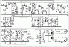
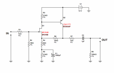
I'm trying to increase the upper Frequency range of that Stage. This consists of 3 Transistors. It can be two as well, but if I use only two then I lose gain.
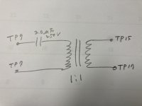
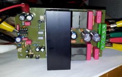
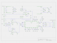
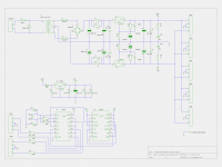
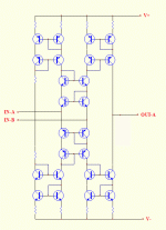
If I use three then Bandwidth will not Exceed 100Khz much. And output of Square Wave and also Sine wave will be Distorted, up to 1% comparing to 1Khz. The Circuit I have uploaded before already but I will upload it again, when I have Commented what has happen last night, in the circuit.

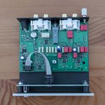
Now, this amplifier again with Output connected is build and it runs, but for my understanding there could be more. and has been tested already, and it sounds great, but I'm not finished with it yet.

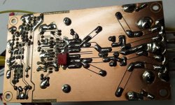
Last night while testing and preparing the PCB, By accident, I reversed somehow the BASE and EMITTER Pins, of the first Drive Transistor. Put on my desk, plugged in my Test Equipment and tested just the output of the second Drive Transistor. This I tested OPEN LOOP, so none Negative Feedback as well Output Transistors weren't connected yet, and applied Power.

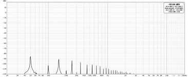
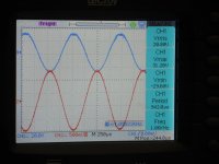
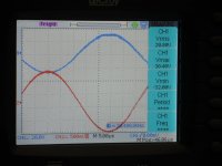
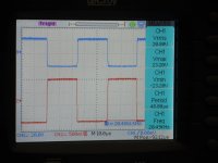
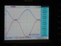
At that Time, this was last night, I didn't knew that I Reversed that Transistor, and started with 1KHz Sine Wave, and pulled up the Gain control on the Function Generator and measured Output on the Collector of the Second Drive Transistor with 25.6 Volt RMS! See Pic 10..

WOW!!! Why, what happen.??? I was stunned about that, so I viewed and controlled the RAIL VOLTAGES and there I thought I saw why, 48Volts, + and 48Volts -.
Oh, yes, of course, output Transistor hadn't been connected yet, OK clear.
So I connected a Load which would Simulate the Output Transistor to 70% and checked the Voltage again. DC V+- read both 43Volts sometimes only 42.9 but equal.

OK. Measured again the Sine and Square Wave of 1khz, still 20.8Volts output before the sine wave would really clip.
Switching the Frequency to 100KHz, again WOW, Clear as the 1KHZ Wave.
Turned Frequency up to 530KHZ till the output would drop down to 16Volts RMS. But no Clipping.

Slowly turned the function Gen backwards, and finally @300K there distortion was gone, and the full 20.0 Volts same as 1Khz where a there.
Now, it was still unbelievable. So I took a 1Kohm resistor and soldered this from Collector to GND.

Now some changes happened. But still 20Volts RMS output at the collector of the Second Drive Transistor. So, lowered that 1K to 600 Ohms and I still got 17Volts output.

So I was very pleased and measured Noise, and Hum and DCV out and all was better that I thought it would be.

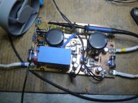
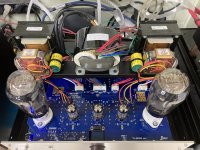
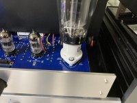
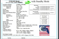
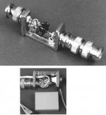
So, I decided to stop working on it, as it was already late night, and today I went back and checked everything because I thought I would connect the Power Transistors and the screwing the board on to the Heat sink. While getting the Drive Transistor in position to screw them onto the HEAT SINK, I saw something strange. The first Drive transistor had no number printed on front of it, or better say LABEL. I use BD139-10. this one are all PLASTIC.

So I took a multiplying lens and checked for the LABEL. and because of these two Transistors, are just besides each other I noticed that the thickness of the left one didn't match the right one, and then I looked at the backside of the left transistor, and there was the label. But hey, the amp was just running fine.

Connected the Amp again and tested again. same as last night exactly. just beautiful. Removed the Wires, dis-soldered that Transistor and used my TR TESTER to check HFE Gain, and it was I noted it down the other day when I made Selection of the Transistors. And one more thing was curious. Usually I need to get some small Capacitors soldered on BC to reduce parasitic noise, just a few Picofarad usually not larger than 33PF. but on this Board, I did not need any.

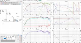
Of course, last night I took Pictures of the Scope and the measurements.
Then I saw in the pictures that the Transistor was running out of Phase by 180 Degrees, and this on all Frequencies.
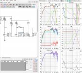
So today, I soldered it back into the PCB, but this time the right way.
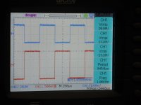
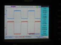
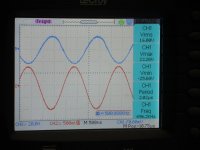
Set up my Instruments and tuned to 1KHZ sine Wave 50% output. first thing I saw, was lots of Parasitic Noise, two small Capacitors together 33 and 22 Pico and the wave was just as beautiful as last night.

I do always search for the max, so Pictures are taken @20.8 volt, where the Wave starts to clip. Sine 500K is 16Volts RMS, still within 2db without clip.

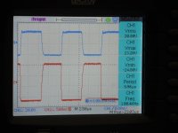
But the follow up was not that nice anymore. 1Khz to 50KHz 20Volts RMS before Clipping, with shunt resistor of 1KOhm to GND.

Above that just Catastrophic. 100KHZ -1db 120 - 2db no way to get higher than 150K would output only 16Volts RMS. Still good but not to compare with last night.

The BD139-10 pin layout is 1= Emitter 2= Collector 3= Base if seen from front where the label is printed. I soldered it with the label to the back, this would mean that E & B were reversed. So how the AMP POSSIBLE COULD work and WORK BETTER THAN when connected the RIGHT WAY.
Has anyone see something similar to this,??
Of course I have pics and I also will place the Circuit. But what you would say just out of the blue has happen. I tried to simulate that today on my computer, yea I could simulate it but with lost of distortion measured in the simulator software, but in real-time there wasn't any distortion.

Does anyone has an Idea,? Shall i put the Transistor the wrong way in to get better number? And after all the world would laugh at me, what a fool..

Thanks for any Input
Regards

Chris Hess

Look at the pics from Last night first. these from today
I will place later..

Attachments

  • 1.Sine 1Khz 20.8 Volts RMS-s.jpg
    1.Sine 1Khz 20.8 Volts RMS-s.jpg
    181.8 KB · Views: 179
  • 1.Square 1Khz 20 Volts RMS-s.jpg
    1.Square 1Khz 20 Volts RMS-s.jpg
    180.1 KB · Views: 171
  • 4. Sine 20Khz 20Volts RMS-s.jpg
    4. Sine 20Khz 20Volts RMS-s.jpg
    179.5 KB · Views: 157
  • 4. Square 20Khz 20Volts RMS-s.jpg
    4. Square 20Khz 20Volts RMS-s.jpg
    179.8 KB · Views: 157
  • 5. Sine 50Khz 20Votls RMS-s.jpg
    5. Sine 50Khz 20Votls RMS-s.jpg
    184.3 KB · Views: 163
  • 5. Square 50Khz 20.8 Volts RMS-s.jpg
    5. Square 50Khz 20.8 Volts RMS-s.jpg
    178.9 KB · Views: 58
  • 6.. Square 100Khz 20.8 Votls RMS-s.jpg
    6.. Square 100Khz 20.8 Votls RMS-s.jpg
    180.6 KB · Views: 63
  • 8. Sine 300Khz 20Vrms-s.jpg
    8. Sine 300Khz 20Vrms-s.jpg
    177.4 KB · Views: 64
  • 8.Sine 500Khz 16VRMS-s.jpg
    8.Sine 500Khz 16VRMS-s.jpg
    181.3 KB · Views: 64
  • PCB Measruring -s.jpg
    PCB Measruring -s.jpg
    252.7 KB · Views: 77

Class D that sounds as good as AB??

I recently compared an old AB power amp (so old it had a single 75V rail supply and all NPN Outputs. I compared it with a tpa3118 (60w) and although not a fair comparison in power rating (the AB amp is about 120w), the old AB sounded a lot more polished and alive. I didn't mind the class D until I "AB-d" them with the same pres (one tube pre and one discrete SS). Maybe class D just can't sound as good? Maybe it was the extra watts in the AB amp?

Bob Pease RIP

Bob Pease sadly killed reportedly returning from Jim Willam's memorial

Two of the “Greats” in Analogue electronics have died recently.

Ironically I’ve was presented a book by Bob Pease on safe driving – with a picture of his VW Beatle on the front cover 🙁

"Word has just filtered through Twitter that Bob Pease was killed in a car accident.

This one by the sounds of it:

Driver, 70, dies in Saratoga crash - San Jose Mercury News

In a sad twist of fate, it is reported that he was returning from Jim Willam's memorial.

A very sad week indeed."

RIP Bob Pease & Jim Willam's- Thank you both for your contributions to the art of analogue electronics!

Samson Live! L612M need schematic

I have a Samson L612M powered monitor to repair -- haven't been able to find the right schematic -- almost given up. I have schematics for the L1212 and the DB500A -- both of these have elements that match up to the L612M, but neither is the right one. The power amp board is silk-screened "DB300A power amp bd" so I assume it shares that board with the DB300A -- BUT, I can only find the DB500A schematic, not the 300. The L612M has a TDA7294 monolithic 100W IC power amplifier -- this is in none of the schematics. Thanks for any ideas about where to find the schematic.

Also must say that this unit is designed in a very screwy way and is not repair friendly at all, woof.

TU8600S with intestage

**** TU8600S with interstage transformer **** sorry for the typo.


Hello,

I am another fan of TU8600S and I toyed with this wonderful amp and I thought what I did may be of interest to some.

In short, I put the para-feed interstage before 300B without changing any given circuit except not using the C104 and C204.

A Fantastic fact about TU8600S is that it has these TP points that make my experiment really easy.

What I did ;

- remove C104 C204 or just cut the PCB path (in the picture)
- Use four TPs to connect the 'cap + para feed interstage transformer' (in the hand-drawn circuit..)
- I used Ludahl LL1635PP. You can use whatever 1:1 interstage. I used PP version because it has no air gap which is an advantage.
- give it some time and listen to it.
- If you don't like it you can put it back to the stock state 100%.
- If you like it move the OPTs(stock version) to the backside a little and fix the LL1635
- I used in-line connectors to compare with the original sound later. 🙂
- beware of the phase of primary and secondary, wrong connection causes oscillation interacting with cathode feedback winding of output transformer.

I was pleased to know that this mod does not change any nice appearance of TU8600S.
About the sound, well I like it but who knows about the taste of who except oneself. As a DIYer, I was once shocked by TU8600S performance and tried to improve my 2A3 SET for some different charm that can be used occasionally with TU8600S.
I can say that my TU8600S has that nice tone of 2A3 now and I am listening to more music. 🙂

Cheers,
Chul

Attachments

  • 2021-02-05 17.54.37.jpg
    2021-02-05 17.54.37.jpg
    240.7 KB · Views: 382
  • 2021-02-05 17.00.13.jpg
    2021-02-05 17.00.13.jpg
    790.6 KB · Views: 368
  • 2021-02-05 17.01.42.jpg
    2021-02-05 17.01.42.jpg
    343.5 KB · Views: 363
  • 2021-02-05 17.00.24.jpg
    2021-02-05 17.00.24.jpg
    644.3 KB · Views: 352
  • 2021-02-05 17.00.20.jpg
    2021-02-05 17.00.20.jpg
    693.4 KB · Views: 350

CRYSTEK 975

hi,
I'm planning to upgrade my DAC with crystek 967 oscillator and its datasheet doesn't provide anything about proper implementation of it.
it does say Load Capacitance 15pf, I would assume that a 15pf capacitor to ground should be placed on the output line (pin 3)
and should any resistor in series be placed as well?
the data-sheet is very poor,
any suggestions are welcome.
thank you.

Attachments

  • crystek 957.JPG
    crystek 957.JPG
    196.6 KB · Views: 200

Two derived rails from one filter capacitor

Hi!

Atached is a psu schematic, based on LM317/337 regulators. I expect to draw around +/- 400ma from the +/- 17v rails (LM317/337). Nothing fancy, quite normal circuit.

But my question is about the part of the circuit i signaled within a square: These are two additional positive rails derived from an RC filter after the positive side of the diode bridge. So, from the diode bridge there is an RC filter 10R/1000uf, and then two LM78xx linear regulators.

I have to say that i don't expect to draw much current from these two additional rails, as they are to supply current to six 24v relays (2880R coils), and two lamps within round vumeters, that i will supply with 8v.

My question is just if the arrangement in the circuit signaled within the square is ok.

Thank you for your advise!!

Jay x

Attachments

Pro-Ject Phono Box S2 upgrade

Hello everybody. They gave me a Pro-Ject Phono box S2 phono pre that has two JRC 2068 op. amps inside, on my old Cambridge preamp I remember replacing these opamps with BurrBrowns, do you think it is possible to do the same thing? I have heard good things about the new OPA1656ID which have high gain and very low distortion. I ask someone who maybe has already made this mod or knows a lot more than me. Thanks again.

Attachments

  • Pro-Ject-Phono-Box-S2-phono-előerősítő-inside-top_big.jpg
    Pro-Ject-Phono-Box-S2-phono-előerősítő-inside-top_big.jpg
    412.6 KB · Views: 1,279

Marantz PM6004 fault

HI, I have a Marantz PM6004 amp which has developed a problem. It was working fine until I went away and turned it off for a few days, when i switched it back on things went wrong.
The output through the speakers was now at a low volume and heavily distorted, i checked the headphones and the output was the same. I checked the input and discovered that the input from the CD could also be heard at a lower volume when changing the input selector to any of the other inputs, i.e. I could hear the CD through the AUX input. I changed the input to say the Phono input and could hear that through all the other inputs.
I thought it may be the input selector chip at fault but couldn't find any shorts across the pins.
Any suggestions as to what to check next?

Are Matched components necessary or worth it?

Hi all,

I am putting together parts for a EL84 SE valve amp build - what’s the view on paying extra for matched capacitors and resistors ?

Is it worth paying extra, does it make a difference , is less or more necessary for a single ended build ?

I have read somewhere it’s not worth paying the extra as the matched pairs don’t remain matched for long once the equip is being used and so is a waist of money.

Thanks

One Last Attempt at Discrete Opamp in DIP8 Footprint

As the film title says, “Never say never”.
So perhaps I should not have used the word last attempt.

Anyhow, a DC-stable discrete opamp in a DIP-8 Footprint has remained unfinished business for me, despite a few attempts over the years.
The previous failures were largely due to DC offsets and unity-gain stability.

In the last 18 months, after much contemplation, a renewed effort was made to take on this challenge one last time.
This time with much better success, apparently.
Nothing really ground breaking. But that is also not where the difficulty lies.


Patrick

.

Attachments

  • 190225 SOPA Top.JPG
    190225 SOPA Top.JPG
    244.2 KB · Views: 2,486

rotel RC-971 upgrade suggestions

hello fellow HI-FI enthusiasts

after upgrading my rc-971 as per this guide --http://whatishifi.blogspot.com/2017/04/modifing-rotel-rc-970bx-and-op-amp-comparisons.html

i did not upgrade to a stepped attenuator, but did replace all of the power circuit caps.
in the signal path i used panasonic fc 25v 1000uf
would the attenuator make a noticeable difference ?
also in the future i intend to add a subwoofer output.

any suggestions are welcome

thanks for reading
gaz

ps couldnt upload schematic because "file to big" and cant take a screen shot on this computer. maybe the forum should have a repository ! i have some i could share.

Multi voltage power supply rail

I have observed that in tube electronics different B+ volages are set by resistor networks, followed by capacitors, for each voltage.

I have a solid state preamp that requires +23@135mA, +5.6V@95mA and -12V@9mV.

How bad would it be if I have a stiff 35VDC power supply with a resistor network, consuming 0.5 - 1A and tap it to get the voltages I need?

This maybe an obvious solution. I am asking because I never see it used in solid state projects.

Thank you.

Teenage Wall Speaker 50$

Teen Wall Speaker 59$

Some 5 years ago Audiovideo.fi designed these Teen Wall Speakers. They were ment to match cheap price and quality sound for teenage kids. Price was about 59$. The drivers were from big stock of leftovers.

Kaiutinrakennusohje Teini-seinakaiutin ja Teinijytky-aktiivisubwoofer - AudioVideo

Bassdrivers: Nokia Harman LPT 145/25/100FS
Tweeter: Nokia Harman LPKH 50/10/100 SKF

Now it seems that the big stock has been consumed and I can't advance in my project to build pair of these. Actually the tweeter is missing. Any help to replace it?

The parts came from Kaiutinelementit - Hifitalo

Edit: parts came available and I used those. Teenage Wall Speaker 50$

FS: Coral Beta 10

Its working but really not in great cosmetic condition

the paper cone split after the pour climate so being overlap with paper.

measure and sound still good.

Asking 550usd include ship to anywhere, in fact the cost of shipping is high as now. The pair of driver easily >12kg

Attachments

  • 1614950370024.jpg
    1614950370024.jpg
    514.1 KB · Views: 203
  • 1614950370048.jpg
    1614950370048.jpg
    981.6 KB · Views: 226
  • 1614950370067.jpg
    1614950370067.jpg
    985.5 KB · Views: 195

Technics Su-V4 Repair

Hey folks,

So I'm working on one of these for a friend. One channel was dead and I diagnosed it down to the STK8050 on that channel plus D308 which is an OA90 germanium diode.

I have a few STK8050s, so I have replaced the dead one. Unfortunately I do not have any OA90 or suitable germanium equivalents. I just have 1N0007s. I fitted one to test that I'd correctly diagnosed the problem and sure enough it's working and sounds great (and the same, to my ears) through both channels. However I don't know if there's any long term issues with leaving this substitution in the amp. Obviously it has a higher voltage drop than the OA90.

The issue is, my friend wants me to just leave it with the 1N4007 as he is moving in two days with the amp and another diode won't arrive in time. Basically I want to know whether to
1. Insist that he leaves it with me until i've got a germanium in and then courier it or something
2. tell him it will be fine for now but he should get it swapped out at some point after he moves
3. tell him it will be fine long term as long as he doesn't perceive any negative change to the sound

Can someone advise?
Many thanks.

Advice for balanced 1khz notch filter

I'm currently looking to build (or purchase) a balanced 1khz notch filter for aiding in measurements. And am not too sure where to look.

There is plenty of advice for single ended options, but almost nothing for balanced.

The twin-T design has been suggested but i'm not sure if simply building a symmetrical version of this would work or not. But also how tightly tolerances would need to be controlled in order for this to work properly. As I don't want one side to be attenuating 998hz and the other 1002hz etc.

Would anyone be able to advise on this? Even commercial options like the QA480 have a fair bit of unit variance and so simply buying two of those to use in a balanced configuration could be problematic.

Thanks!

SB Acoustics SB17NAC35-4 measurements!

Hi everyone,

I just want to share some of my measurements of the SB17NAC35-4 mid-woofer.

If you searching for a great performing hard cone mid-woofer, the SB17NAC35-4 is an excellent option.

Thanks to the cone geometry and shape, it has very good control of the cone break-up and it's a very low distorting driver.

It will be great fun working with this mid-woofer! 🙂

For details see: SB Acoustics SB17NAC35-4 Measurements!

/Göran

Attachments

  • SB17NAC35-4_7.JPG
    SB17NAC35-4_7.JPG
    59.3 KB · Views: 2,912
  • SB17NAC35-4_8.JPG
    SB17NAC35-4_8.JPG
    60.5 KB · Views: 2,876
  • SB17NAC35-4_9.JPG
    SB17NAC35-4_9.JPG
    62.3 KB · Views: 2,856
  • SB17NAC35-4_10.JPG
    SB17NAC35-4_10.JPG
    65 KB · Views: 2,865
  • SB17NAC35-4_1.JPG
    SB17NAC35-4_1.JPG
    65.3 KB · Views: 2,814
  • SB17NAC35-4_2.JPG
    SB17NAC35-4_2.JPG
    64.5 KB · Views: 514
  • SB17NAC35-4_3.JPG
    SB17NAC35-4_3.JPG
    60.7 KB · Views: 555

4 x BTL 300W/8R - a TDA8950j based 4 channel power amplifier

*** NOTE: latest gerbers in post # 81 *** NOTE ***


Just 4 fun I have designed (now some years ago) a 4 channel class D power amplifier to get some feeling and knowledge about building class D amplifiers.
Attached some schematics and pictures of the result.
After searching for a simple chip I found the TDA8950j which has from low to mid range an acceptable good THD performance.
The TDA8950j can be clocked externally which I have used in this design to avoid interferences of the different pwm clocks in the audible range.
Maximum output power per channel is 300W/8R.
The amp pcb is single sided and uses some smt devices to save space and to fulfill some datasheet requirements.

For DIY use only feel free to build your party power machine.😉

BR, Toni

Attachments

  • 1200x900-2012-03-04 18.25.50.jpg
    1200x900-2012-03-04 18.25.50.jpg
    58.6 KB · Views: 2,963
  • 1200x900-2012-03-04 18.51.55.jpg
    1200x900-2012-03-04 18.51.55.jpg
    155.2 KB · Views: 2,633
  • 1200x900-2012-03-12 19.26.59.jpg
    1200x900-2012-03-12 19.26.59.jpg
    128.4 KB · Views: 2,533
  • 1200x900-2012-04-01 17.28.09.jpg
    1200x900-2012-04-01 17.28.09.jpg
    122.9 KB · Views: 2,503
  • 1200x900-2012-04-01 17.32.34.jpg
    1200x900-2012-04-01 17.32.34.jpg
    215.4 KB · Views: 2,477
  • 1200x900-2012-04-01 17.33.11.jpg
    1200x900-2012-04-01 17.33.11.jpg
    198.4 KB · Views: 1,397
  • tda8950_btl_schematic.png
    tda8950_btl_schematic.png
    148.8 KB · Views: 2,446
  • tda8950_btl_schematic.pdf
    tda8950_btl_schematic.pdf
    19.5 KB · Views: 758
  • class_d_preamp_powersupply_schematic.png
    class_d_preamp_powersupply_schematic.png
    125.5 KB · Views: 1,853
  • class_d_preamp_powersupply_schematic.pdf
    class_d_preamp_powersupply_schematic.pdf
    19.6 KB · Views: 657
  • Like
Reactions: stewin

Anyone can help with identification of these B & O speakers?

Hello, bought these on Taobao. As seller says, these come from scrapped Bang and Olufsen portable audio products, but due to copyright (LOL) reasons, he can't tell me the models. I've watched several youtube videos for B & O Bluetooth speaker disassembly, and these definitely are B & O - Very similar mechanical design and marking style, but no exact match. Maybe someone can ID them? They are approximately 2.5 and 2.75 inch diameter, smaller one being marked as RADMERSPWM908402NA, and bigger one as LIDMERSPWE8164009S. The QR code on them contains that marking, nothing else.

Attachments

  • beo1.jpg
    beo1.jpg
    155.3 KB · Views: 113
  • beo2.jpg
    beo2.jpg
    160.4 KB · Views: 107
  • beo3.jpg
    beo3.jpg
    170.6 KB · Views: 109
  • beo4.jpg
    beo4.jpg
    335.9 KB · Views: 113

Tango Output Transformers

**update : This item is now sold **


a pair of tango output trans 8k : 600, decommissioned and dismounted from a working preamp.
they are modeled as 11360 because these are custom-made by Tango ISO.
Max dc current 45mA.
Asking for 500USD for the pair. These are huge and heavy, 5kg shipping weight, hence may cost quite a bit. Posting pics failed. Those who are interested in pics and shipping cost can PM me.

They are similar to the trans sold here :
NO-11360 TANGO - HiFi-Do McIntosh/JBL/audio-technica/Jeff Rowland/Accuphase There are no presence of the usual base plate as shown in the pics, because these are not off the shelf models

Philips CD-880 playing speed problem

Hi,

My Philips CD-880 playing speed is erratic. The speed it is more like holding the fast forward button. This is just by click on the play button and play the CD normally. It plays faster on its own.

On top of that, I also noticed the fast forward and fast backward buttons seem not respond or function well.

Are these issues related and am I able to fix it myself with the help of your insight? I really appreciate your thoughts!

Thanks,

usb/spdif volume is too high

I'm having another usb/spdif problem after 9 years( first one was m2tech evo usb converter +8khz 3db roll off) one of me usb converters have unusualy high output level ( chineses brezze audio xmos u8) comapring to others usb/spdif converters which have also xmos u8 chip. without changing anything on analog setup its louder by 8db. i barely can adjust digital volume on pass labs xa200.5 to mark levinson dac's in foobar- it very loud from the very begining. i have checked all three outputs of that converter -spdif/ XKLR aesbu and optical- levels are the same(8 db louder than other converters) . i always thought that spdif format output level is standartized and fixed? 😕 any way to reduce output?

Favorite Threads and Posts in "Power Supplies"

Favorite Threads and Posts in this Forum

This permanent thread is a place for links to threads or posts in this particular forum that are useful and/or exemplify the best of DIY Audio.

This is so others- especially newer members can find them. Feel free to post with these links and a brief comment on what the thread discusses. Occasionally the moderators will consolidate them into fewer posts.

Building an open embedded audio applicance.

For quite some time I have been interested in streaming direct from an embedded system to an Asynchronous DAC.

I did this many moons ago using a beaglebone, and later beaglebone black, but while the results were great - I was not entirely happy with the complexity. I basically had a custom kernel and ALSA modules. In short more than I was happy to share, and it took far more effort than the average Joe would care to undertake.

Recently however the folks behind Raspbian and especially Florian Meier with his contributions to I2S modules have made me take a much closer look at the raspberry pi - particularly "model B - revision 2". The addition of P5 and the newest Raspbian and Volumio builds make it possible to have an incredibly good I2S based music appliance by simply adding a great DAC - such as the Buffalo III-SE - which works perfectly - but you could just as well use any asynchronous I2S input DAC.

Using the raspberry pi with the B3SE is very simple. I have tested two scenarios - each with distinct advantages.

First pi -> DAC direct.

This is really simple:

just wire P5 to the DAC appropriately - as show in the attached picture. Pin 1 is indicated on the rpi by the square pin. And P5 is located right next to P1 (directly below with P1 oriented at the top).

The best news is once configured you can use the pi as an airplay receiver (with a mac) for audio (at 44.1khz) and as a direct audio appliance at up to 192/32bit sample rate (the limit of ALSA at the moment).

I have mine streaming directly from NAS (an ASUS RT-AC66U with a USB SSD drive) at up to 192Khz sounding superb! No complaints. The sound is incredible.

The second method I will introduce if there is enough interest.

Here is detail you will want if setting up Raspbian, or Volumio for B3SE.

make your /etc/modules file looks like this:

Code:
snd_soc_bcm2708
snd_soc_bcm2708_i2s
bcm2708_dmaengine
snd-soc-pcm1794a
snd_soc_rpi_dac

I am happy to help anyone who has any further questions on how to make it work.

You won't be disappointed with the results.

I have developed two different USB -> I2S modules, and I have yet to find any reason to use one of those over this much more direct approach. Especially for the Buffalo III-SE.

Cheers!
Russ

Attachments

  • Screenshot (1).png
    Screenshot (1).png
    4.8 KB · Views: 10,301

Got some AD149's and bored.

I got about 100-150 GE PNP TO3 transistors.Mostly AD149 and ASZ series. But also about a dozen 2N555


Now Ive only ever done a P3A amp to replace a guitair amp for someone.


Is there any point in making an amplifier out of these? Just for fun. I can imagine i need to figure something out to avoid thermal runaway.


I got some MAT02's that could serve as the differential front end.


I can do board design just fine, im just wondering if there is anything worthwile to build with these.

Introducing... Me? Hi!

Hi DIYAudionauts

I've peeked in on this forum on and off during my all-to-frequent searches on amps. Figured I might as well join and engage.

I'm a guitar player and have been for many moons. I predominately play blues rock/hard rock.

My main amp is a Peavey Classic 30 running through a 212. The Peavey is currently in a coma, though I think it's a blown fuse which leads me to think it's probably a power tube issue (I had noticed the overall amp volume was significantly reduced prior to the issue). I haven't been in the mood to pull the chassis and inspect because it wasn't long ago I was in there for other reasons and it's a PITA to deal with considering the folded PCB. I plan to recap it while I'm in there fixing whatever, as well as maybe replacing the tube sockets. Anyway, I'll get around to diagnosing it here in the next week or month or so.

I am by no means an amp tech expert but I'm a smart cookie and I'm comfortable with electronics (I've made minor amp repairs in the past as well as modded and built pedals and such).

I have a few other amps. I'm currently playing an Orange CR120 which I sometimes love, sometimes don't (right now we are on pleasant speaking terms) but gets the job done. I also have an Orange Micro Dark running through a 110 cab that I sometimes like better than the CR120. The gain is just a bit more pleasing on that thing, maybe due to the pre-amp being valve. *shrugs*

Lately I have been messing around with a Roland MicroCube that my fiance bought years ago but never really used (the older version, not the newest line) and I'm really kind of impressed with the 1987x setting on it and given that it's a 2watt w/ 5" speaker, I can get pretty gainy with it if I want and not worry about waking anyone up, though I generally don't have to worry much about volume issues here. It's just sometimes at say, 3am, I like to err on the side of caution.

While I love my Classic 30 to pieces I am considering the SV20H at some point or maybe even a lower wattage similar type of amp, finances and necessity providing.

I think that'll do for an intro/first post.

Cheers!

Speaker project recommendation

Hello everyone, my name is Chris.

I'm sure this question has been asked a thousand times, but I just haven't been able to find exactly what I want. I'm looking for a speaker project with plans and BOM. I can do all the woodworking, sourcing parts, etc. myself.

I have an amp that is 10watt @4ohms, so the speakers need to have decent sensitivity. Size can't be much more than 4, maybe 5 foot tall, width and depth not much of an issue. I mainly listen to classic rock from the 60s to early 80s, so I'm not needing super bass or anything like that.

Also keeping it affordable is another requirement, as my audio equipment is not high end, and I'm not an audiophile. My current speakers are over 40 years old as well as most of my setup. They sound good to me, but could be better. Any suggestions, or resources for a project would be greatly appreciated.


20210206-180543-2.jpg


This is my current setup.
Fisher Studio Standard, Receiver RS-2004A, Cassette-8Track Deck ER-8150, Turntable-Linear Motor 120 Pole MT-6224,
Amp-MP PureTube

Is High Frequency Switching Noise Worth Filtering?

I'm working on designing an op-amp based headphone amp, and I'm currently working on building the power management section of the circuit. I'm using a +/- 12V switching split power supply, which is then fed into +/- LDOs - LT3080 and LT3015. I can see on my oscilloscope that both the pre- and post- regulated power signals have high frequency ripple, about 75mV peak-to-peak @ 100Mhz. This makes sense since the LDOs have very poor ripple rejection at such a high frequency.


My question is, is this signal worth filtering? In my mind, such a high frequency signal is way out of the audible range and thus shouldn't affect the output of the op-amps in any audible way. However, I admit that I'm a bit of a novice when it comes to the power supply side of things, so I could be overlooking something obvious. Thanks in advance!

Regulator for Pre-amp

Hi folks

I've built a pair of this simple JFET pre-amp, substituting a BF256B for the BF245B and a 2SA1175 for the BC560.


I'm wondering how to power them, what sort of regulator to use, there are so many options from the humble 78xx IC to really complex fully discrete circuits.


I'm not sure how exotic a regulator this circuit needs to sound good, I like the idea of a discrete circuit rather than an IC, but would that be overkill for this pre-amp?


Is there a discrete circuit that offers better performance than a 78xx or LM317 that is pretty simple with a fairly low parts count?


I'm open to suggestions and in need of guidance.

Attachments

  • jfet_simple_preamp-8b38574.png
    jfet_simple_preamp-8b38574.png
    84.9 KB · Views: 1,195

DIY amp recommendation for B&W 684 S2 speakers

So im looking to build my first amp from scratch to power a pair of BB&W 684 S2's. I've got quite abit of experience repairing older amps, and I own a pretty complete electronics lab too as im studying EEE at university.

I almost want to design my own from scratch, but at this point i think class AB BJT power amps have little room for re-invention.

Any ideas what so ever are very welcome! thanks!

Volume Pot and Preamp

I am thinking about buying Aiyima A07 and pair it with the preamp below. For convenience volume would be controlled via the preamp:

Dayton Audio WBA31 Wireless Wi-Fi & Bluetooth Audio Receiver with IR Remote

My questions are:
  • Does the volume pot impact sound quality? Because I will have a preamp, am I better off removing the volume pot?
  • Alternatively I can consider buying an amp board without volume pot
  • If I turn the Aiyima volume pot all the way up, would it be similar to having no volume pot at all? Or am I better off leaving the volume pot about half way up?
Thanks in advance.

Hickok 750 owners help!

Hi,


got a fairly nice tester that had some previous work on it, and for a reason there is an alone loose wite going nowhere?
Of course it does have to be related to the Short selector, but where it should be connected?


From the facing plate this wire is on the 4th deck of the shorts selector.
It is white/black stripe.
From ohmeter measurement it connects on position 3-4-5 to the same 4th deck going to a red wire that is connected to R21 , a 47 ohms resistor on the screen selector.


A bit of search yes helping with the schematics, but still parts are unidentified inside the Hickok 750.


either this wire was cut? Or it is going to a nearby selector, switch ot post, it is actually about 6 inches long, so it cannot acroos the whole tester??


See the pictures...


Otherwise the 49 small bias fuse light bulb is burned. Trying to find some replacement.
I could do line test fine, so meter circuit id OK.
But cannot test a 6L6 for Gm or emission, no needle mouvement...

Attachments

  • 20210301_104202.jpg
    20210301_104202.jpg
    1 MB · Views: 178
  • 20210301_104257.jpg
    20210301_104257.jpg
    1,010 KB · Views: 148

Diy Build Guides

I was looking around on the “new under construction” Diy Build guide page to see if any projects had been added, and saw a new build guide for the “Starving Student II” headphone amp/linestage by 6L6? However, None of the links for the DiyStore or threads work with a message of “page not found” error when clicked. I’m assuming this is another great project soon to be available since the build guide seems ready to go? Looks like a good one! Any teaser info would be great 6L6!

Attachments

  • 880130ED-8071-4415-B0DB-3D44AD6823CF.jpeg
    880130ED-8071-4415-B0DB-3D44AD6823CF.jpeg
    315.4 KB · Views: 419
Projects by fanatics, for fanatics
Get answers and advice for everyone wanting to learn the art of audio.
Join the Community
507,844
Members
7,890,439
Messages

Filter

Forum Statistics

Threads
406,357
Messages
7,890,439
Members
507,844
Latest member
Amirbutt