ALEPH X

Good evening guys
For sale
If anyone is interested in an AlephX, I have had the circuit boards here for a long time and can't get around to realizing them. ALEPH DIY circuit board with the thickest gold-plated lines (100 nm) on FR4 circuit board. 20,5cm x3,5cm x 3mm .At the same time, the assembly of higher quality components has been made possible. the price was 49 € per board. The boards were made by Refentaudio. In addition, all resistors and potentiometers from Digi Key, and transistors of the irf 9610 are matched. On the board, the diameter of the soldering connections are slightly wider, so that higher quality components fit. I don't want to enrich myself just to get what I have spent. I can send you Digi key invoices and bom and schematic by email.one Link von denTrafos.
There are also two transformers 2x12V 400W they bought as good as new, but the film down below is worn see pictures. One weighs 3.8 kg alone. Link above trafos and Dokumentation:
Security Check

All resistances are always 2 more than you need, what is set in brackets on the bomb list is part of it.
excuses my translation.

I would have 320 Plus shipping.
Greetings alfred

Attachments

  • DSC08870.jpg
    DSC08870.jpg
    822.6 KB · Views: 905
  • DSC08878.jpg
    DSC08878.jpg
    853.9 KB · Views: 886
  • DSC08873.jpg
    DSC08873.jpg
    788.5 KB · Views: 855
  • DSC08872.jpg
    DSC08872.jpg
    757.5 KB · Views: 835
  • DSC08877.jpg
    DSC08877.jpg
    594.6 KB · Views: 813
  • DSC08902.jpg
    DSC08902.jpg
    510.9 KB · Views: 273
  • DSC08903.jpg
    DSC08903.jpg
    527.7 KB · Views: 272
  • Bild (54).jpg
    Bild (54).jpg
    508.5 KB · Views: 247
  • Bild (53).jpg
    Bild (53).jpg
    386.6 KB · Views: 232
  • Bild (55).jpg
    Bild (55).jpg
    381.9 KB · Views: 283

question about a circuit

hi i wonder if one of you could help with the attached as im trying to understand something


in the attached you see the 2 main secondary outputs to the main board on this nad 3130 amp
im kind of getting to understand things a bit now, but one thing here i dont understand, unless there is a mistake, is why the ac voltage appears to go straight out to circuit(circled in red) where the other one (circled in black) goes only through the rectifier, as i would have expected it to do.


many thanks

Attachments

  • circuit q1.jpg
    circuit q1.jpg
    281.7 KB · Views: 128

Car stereo problem

Right, I've been trying to get an answer to this for weeks now.


I have a "CD 30 MP3 car radio" head unit with a paired display.


The wiring loom doesn't come with the connector in order to connect the display.


I know it is possible to connect the radio with the display without it being in a car as I've seen pictures of it. The pictures never show the back and nobody can or wont tell me how to connect the display to the head unit. I can make up my own loom however I need to know just a couple of simple things which shouldn't be that complicated.


How many wires connect from the display to the head unit? and where do they go to?


Please please could somebody reply because I'm losing my damn mind over this.


Thank you.

Primaluna Prologue Four mods/upgrades

I've had a new Prologue Four for a few months now. The midrange was a bit shouty/ screechy. I've replaced the 2 small 'Realcap' caps in the input section for same value 'Mundorf Evo Oil'. This added clarity to all frequencies. I have now replaced the input resistors to TAKMAN carbons. This has really cleaned up the screechy midrange. I will eventually replace the other 4 'realcaps' on the autobias board.

Just wondering if anyone else has any advice or experience with similar simple mods to primaluna. I also have the Prologue Premium Pre. These are great amps for the money.

Measuring speaker driver with high impedance source

Usually I measure driver impedance just by sweeping with my function gen. It has 50ohm output impedance and to make the measurement easier I add 50ohms in series, so a total of 100ohms. I use a PC scope and with the peak hold on the FFT I get decent sweeps.

Question is: When having the high series resistance, and thus very low damping factor on the speaker driver, doesn't this shift fs up/down, make the Q appear larger than it is, etc?
Is it more accurate using a power amplifier with a very small value series resistor and then measure both the voltage and current?
Does it matter? Will either method be accurate enough?

Noob wants to build something for DQ-10's

I'm looking to build a class D PA for my Dahlquist DQ-10s. I've been using a Class A DH-500 for years, but with the new digital inputs (Sonos), I want the flexibility of a class D so I can leave it on all the time. Problem is, I need 250W a side, and it doesn't appear that there's lots of that.

I'd like to build two monoblocks and use my Hafler chassis to house it all. Problem is, I don't know where to start. I do have some experience - built the DH-500 and have modded the crossovers in the DQ-10s, but I'm really a noob.

Any ideas?

Analog Delta-Sigma interpolation DAC

What is Delta-Sigma? In quantified math is the same as derivative-integral in linear math. In electronics with limited frequency is simply high pass-low pass. The most known is the recording-playback RIAA curve. As on records the high frequencies which have much smaller amplitudes than the lowers, physically the groove will contain very little information about high frequencies, besides the hiss of the stylus friction noise. If the signal is recorded with the derivative function, the high frequencies are better described and on the playback the integrator cleans the hiss of the stylus bringing back the initial spectrum.
This is to be applied on the DAC to eliminate noises created by switching spikes internal R2R noise and due to step character of the analog converted signal.
The Delta hence is the difference in level between the actual and the preceding sample. I only need to delay the signal one clock and subtract with the actual and I get the derivative function

attachment.php


The left circuit shows this, the signal from the sampler 44khz is delayed 22us and the subtracted signal now is a cosine derivative of the input.
Now, if I integrate back the signal all the DAC noises will be attenuated and the step cosine will become ramped sine wave. The signal with 1khz becomes too clean sinusoidal , I increased to 8khz to be compared with the step wave. You can remark that very little filtering is necessary.
All is not bright, instead of sigma (accumulating discreet values) as I integrated it, the high frequency information in step is eliminated and the DAC has -3db response about 11khz. Band pass filter might re equalize but the lost information is not valuable, better can be done by interpolation that I explain in few.
To remark that the Delta is described with double precision than the signal occupying 17 bits.

Attachments

  • analog delta sigma.JPG
    analog delta sigma.JPG
    157.9 KB · Views: 3,038

HRT microStreamer distorting badly on line- and headphone-out

Hey guys!


I just got a pair of DT 1770 to use for commuting, replacing my Sennheiser Momentum Wireless. Thus, I need a portable amp. I have an old HRT microStreamer which have been dead for about 5 years which I want to fix if possible!


The amp distorts heavily on both line-out and headphone-out, using the headphone-out it almost sounds like there is a clean unamplified signal in the background which gets distorted as soon as the amp needs any power to drive the headphones. But don't ge me wrong, it's constantly distorting.


It might have broke by the amps chassis grounding in the cable channel beneath my desk, the amp made some audible noises when contacting the metal before it broke. Kind of weird as the channel shouldn't have been grounded and it's painted, but it probably connected with some other PC equipment also.


Does anyone have an idea what could be wrong? A bad capacitor in the powerfeed to the DAC?


The components are surface mounted, but I've got a friend who's worked with surface mount soldering so we might be able to fix it if we figure out whats wrong.


I've thought about sending it to HRT as well, but their homepage seems inactive. Are they still in business?

Thankful for all help! 🙂

//Peccz

6SN7 operation point question for y'all

I rarely post here but sure do value this community!

I am wondering (as I've had trouble figuring this out) if anyone could help with this. I have just enough tube/circuit knowledge to get in trouble and have been continuing to learn when possible. I've built maybe a dozen amps and finally can get most of them quiet now. Just to provide a little background on who you would be replying to. Intermediate/beginner here.

Attached (hopefully) is my schematic for the circuit in question. Please excuse the personal notes on brands etc. This is a plate reactor loaded 6sn7 with which I have limited B+ to work with. I am wondering about the voltage at the cathode resistor which is 7V. My DAC puts out 2v and my lineamp is unity gain. How can I figure out if I am in danger of clipping or if this operating setup is safe? I don't hear any problems but don't have a scope to test. I know that my cathode resistor value is higher than most at 1500 ohms but am very happy with the sound in this setup. Just don't want to damage anything. I experimented yesterday with raising the B+, lowering the cathode resistor value etc. but ultimately preferred the sound with the higher value cathode resistor (much tighter bass). This is the first time I have not used a resistor on the plate of the 6sn7. The 2 sections are paralleled (don't think I mentioned that on the schematic.) I am used to seeing closer to 2v at the cathode resistor.

Attachments

DIY tube electric guitar preamp for jazz/blues (not rock)?

I find it hard to believe that no-one has posted this question to this forum before, so here goes...

I'm a jazz and blues guitarist. I play 'clean' but actually I like the kinds of sounds you get from a Gibson-style humbucking pickup on a hollow-body/archtop electric guitar into a classic tube amp like Fender Vibrolux or Deluxe combo amps.

I have one of those amps, but I don't gig anymore, and it's just too heavy.

Now that there are all these great cheap power amps available, I thought it might be nice to wire up a guitar preamp that emulates the sound of a late 1960s Fender 'black-face' combo amp. Of course the sound of the amp is hugely influenced by the output stage including output transformer, choice of speaker, what cabinet the speaker is in, and so on.

I do find that you can make a low pass filter that simulates the high frequency roll-off of a classic guitar speaker like Jensen C12N or similar.

What I don't know is how to emulate the nice compression effect one gets from a Fender Deluxe Reverb played at a moderate volume level. Not 'distorted' in the rock sense, no fuzz to its tone, but 'enriched', 'warmed up'.

Do you think it would be possible to put a cathode follower at the output of a Fender 'clean channel' with 12AX7 and tone stack, and bias an output stage CF up so that it compresses easily? Or maybe use a pentode after the tone stack and set it up so that it has little headroom, so compresses the 'clean' signal?

Has anyone tried these things?

Just curious if someone has built something like this that has worked out for them.

Thanks.
--

VSPSX very simple phono stage + x

The design idea originally featured in my diyaudio blog.

It's the single op amp IC phono stage of the VSPS, with a discrete solid state buffer and shunt-source voltage regulator.

In this thread, we'll develop the board layout, get some boards made, and offer a special "guinea pig" trial of boards/parts to anyone interested in building their own over the holidays.

So first off time to fire up Eagle 7.7.0 and get busy with the layout.

Latest LTSpice version attached. Part numbers not consistent with BOM.

Attachments

  • VSPSX.asc
    VSPSX.asc
    13.2 KB · Views: 140
  • vspsx.png
    vspsx.png
    61 KB · Views: 1,332

FS: 25MHZ, 2ch, 12-16 bit USB scope with sig. gen.

Looking for a good home for my TiePie USB scope.
2 channel, 25MHz, 8, 12, 14 or 16 bit resolution depending on bandwidth.
Includes a 14 bit function generator.
Multi-Instruments software downloadable for free from TiePie.
Perfect for audio use!

Software provides functions of:

Oscilloscope
Spectrum analyzer
Data logger
Multimeter
Arbitrary Waveform Generator
Protocol analyzer

Product page is here:

Handyscope HS3 | 100 MS/s 12-bit dual channel USB oscilloscope with function generator

The 25 MHz HS3 retails at € 942. I am asking € 250 + shipping.

Jan

Attachments

  • HS3 specs.jpg
    HS3 specs.jpg
    599 KB · Views: 251
  • tiepie product page.PNG
    tiepie product page.PNG
    216.3 KB · Views: 249

TO-220 6V Regulator

I am trying to use 6v 1.5A regulators to heat ECC88 valves. I have approx 12.2DC going in and with one valve connected I get a little over 5v out with a very slow voltage build up. If I put 28DC in I get nothing out like it's shut down. The heater current is 600mA so what is going on ? Have I been sold some bad regulators, they did come from Spain ! It is mounted on a heatsink and never gets too hot to touch. Any idea's anybody ??

Drip Audio Otpo 7 res problem

Hi so im new here. Im building an opto 7 and it looks like some of the resistors from Digi-Key that I need are either discontinued or have to be ordered in bulk of 1000 or more and I only even need 4 of them lol. My question is can I order another brand of resistor for my project from another site or does it have to be that certain one in the parts bom from Digikey? I'm missing part numbers
RC12JB240k-ND 240k 1/2W 5% Axial
RC12JB100K-ND 100K 1/2W 5% Axial
and RC12JB1K50-ND 1.5K 1/2W 5% Axial
Any help would be great 🙂

Luxman tube amp capacitor replacement

Hello,

First of all I would like to apologise for this silly question - its been more than 10 years since I've built an amp myself or touched a soldering iron really. I've forgotten so many things. Please let me know if this is not a place for such question and I will delete this post if thats the case.

I have this tube Luxman amp from the 80s that I am planning to recap.

The problem is that I cannot find replacement units for these.


Searching by the code on top yields zero results. They all have 4 pins which I believe I never dealt with. Maybe you guys could lead me on a path?

10" two way

The Seas CA26RE4X and the 27TBCD/GB-DXT look like candidates for a possible 2way if crossed at 1300-1400hz

Has anyone thoughts on this combo.

I always liked the sound of a 10" two way for classic rock and these drivers might make a nice larger stand mount/ bookshelf type speaker.
Maybe a variovent type enclosure to keep volume reasonable.

I would assume a higher order crossover would be required but I could be wrong.

Thanks !


John

Few extra PCBs for 120VAC to +/-12VDC power supply unit suitable for RJM projects...

Hey y'all, I'm in the process of building a VSPS and drew myself up a PCB for the power supply unit that I'm going to build. Fab from JLCPCB comes in units of 5, so I'll have 4 leftover. Willing to send them to anyone interested within the US for just the cost of shipping (<$10 thru USPS) 🙂 Just post here or send me a message if you're interested.

Here's the schematic and board layout; it's quite simple, just a fuse, switch, 120-12V dual-primary, dual-secondary transformer, and dual bridge rectifiers made up of individual diodes (in the same manner as RJM's DBRD board):


WlkOmVr.png

kqtcwWo.png


Board is 83x85 mm, designed to be installed in one of these enclosures off Amazon, though it has screw holes that you can use to mount it pretty much wherever you like: https://www.amazon.com/gp/product/B07HBWLZDQ/ref=ppx_yo_dt_b_asin_title_o01_s00?ie=UTF8&psc=1

Here's the necessary bill of materials to complete the build... you'll definitely want the same transformer (FP24-250) and fuse clips, but you can choose your own diodes, fuse, input/output terminals, and switch if you want

12V Split Power Supply - Google Sheets

Skar LP1000. 1D transistor identification.

Need some help identifying what these 2 transistors were to repair this amplifier. What would be a good substitution in hole to-92 package. Think got it fiqured out now. I got the card operational now so pin 1 are my collectors

Attachments

  • 16156447680087886946525591437402.jpg
    16156447680087886946525591437402.jpg
    893.4 KB · Views: 103
  • 16156447969873717920242338955179.jpg
    16156447969873717920242338955179.jpg
    906.6 KB · Views: 96

FS: MiniDSP OpenDRC-DA8 Audio Digital Processor DSP 32bit S/PDIF RCA

I am selling a MiniDSP OpenDRC-DA8 Audio Digital Processor DSP 32bit S / PDIF RCA 8 channels with remote control, bought 6 months ago for which it is still under warranty and in perfect condition with the plastics

The price is € 385 + shipping


The openDRC-DA8 from MiniDSP is a multi-channel audio processor with floating point DSP at an affordable price. Powered by an Analog Devices Sharp ADSP21369 processor, the OpenDRC-DA8 engine enables complex processing such as digital room acoustic correction, active filtering for type IIR and FIR loudspeakers with high-level phasing speakers.

To obtain a fully functional device:

Measurements will be acquired with the microphone not supplied Umik USB 1.
Use the REW software for IIR correction measurements and curves: REW - Room EQ Wizard Room Acoustics Software
Follow this tutorial in English for filtering FIR.
The OpenDRC-DA8 also acts as a DAC (AKM AK4440) with its digital input SPDIF and its 8 analog RCA outputs. With its Asynchronous Sampling Rate Converter (ASRC), the digital signal is processed with a low jitter. Once configured, the configurations (4 in total) and the volume can be controlled via the rotary encoder or a remote control (not supplied), without the need for a computer.

Finally, the OpenDRC-DA8 as most MiniDSP products is intended to be an easy to use system, driven by a large community on the web working to improve and evolve the product constantly.

mini dsp DA8

Schematic diagram

TECHNICAL CHARACTERISTICS

Processors: Analog Devices Sharc ADSP21369
Processing type: 32bit floating point
Type of digital filter: FIR and IIR
Convolution engine for advanced / custom filters
Input: SPDIF 24bit 192khz
Outputs: 8x RCA Stereo with 2V Impedance 560ohm
FEATURES
DAC AK4440 with 8output channels
Front volume control
Remote controlled volume
Recall of 4 memorizable configurations
Active filtering 2x4 channels (8 channels)
Parametric Equalizer on 8 Channels


IMG-0090.jpg

IMG-0091.jpg

IMG-0092.jpg

IMG-0093.jpg

IMG-0094.jpg

Hybrid PCB Components with Free Test Before Assembly

News:

Upon receiving circuit board components, testing to them is a nightmare before the PCB assembly. But now, you can order hybrid electronic components from PCBONLINE, a one-stop circuit board company, providing free testing to components. Here is the website: Electronic Component Distributor - PCBONLINE.

Send your bill of materials to us, and you can get high-quality original electronic components that are traceable.

Email us at info@pcbonlne.com.

Full Bridge D-Class 2000-2500W Operation Wanted

I found many documents and examined them all. I saw he was wrong. In the comparator part, the tl072 compensation capacitors are reversed .. Ne555 150uf-10nf in the ocp part - it does not go on the line .. I pressed the PCB, then I saw the errors when I checked it. I said I'm going to make another card and I saw that they were not good. I would be glad if there is a full document as sprint layout or pdf. It must be ocp.

Attachments

curved enclosure building in the midwest

Are there any members here or do you guys know anyone in the Midwest who is reasonably priced and can build curved edge enclosures like shown here:

Smart Corners by Mobile Solutions - Tool Overview - YouTube
I'm considering doing a home theater subwoofer enclosure build and I want it not to look like a standard box in my living room.

I'm hopping to build something with a >90deg round corner to sort of mimic my old trusty infinity kappa 8.1 mains.

Infinity Kappa x.1i und x.2i Serie

I want the enclosure made primarily from 1" Baltic birch, with obvious use of MDF in the corners. I need a 22" height front baffle, (total cabinet height 22.5" with 1/2" rubber feet). and total net volume of 4.5cu-ft after internal bracing and driver displacement of .34cu-ft. and the driver has a 16" mounting depth. I want the cabinet with minimal height, reasonably low depth and vary the width of the front baffle and the angle on the curved front corners to accommodate the volume necessary to reach the target 4.5cu-ft net.

If anyone here is willing to build an enclosure for me or can recommend a reasonably priced person/shop in the IL/IN/WI/IA area feel free to reply here. I have a few other feelers out there. Hopefully I can find someone good with pricing within reach. Thanks!

RCA-4-117-01 Eagle part confusion

Dear Sirs and Madams!

I am being confused of Eagle part RCA-4-117-01 (RCA Input Jack), here is schematic:
An externally hosted image should be here but it was not working when we last tested it.

and pcb footprint:
An externally hosted image should be here but it was not working when we last tested it.

Now, as you can see, part itself has 6 connectors, but I do not know how to wire it with audio input signals, i.e., does this part represents 4 input jacks, as here:http://www.produktinfo.conrad.com/datenblaetter/725000-749999/736910-da-01-ml-CINCH_ANSCHLUSSPLATTE__4_POLIG_de_en.pdf
or 2 input jacks? Has someone worked with this part and can send some images/pictures of it?

Sincerely,
M.

FS: Hagerman Tuba headphone amp

Hagerman Tuba headphone amp for sale. Used less than 10 hours. It's an excellent amp; I'm selling because it's not a good match for my headphones. $500 firm + shipping. See the Hagerman Audio Labs site for details & manual.

Attachments

  • DSC03581.jpg
    DSC03581.jpg
    514.9 KB · Views: 225
  • DSC03582.jpg
    DSC03582.jpg
    518 KB · Views: 214
  • DSC03583.jpg
    DSC03583.jpg
    521.6 KB · Views: 199
  • DSC03584.jpg
    DSC03584.jpg
    507 KB · Views: 193
  • DSC03585.jpg
    DSC03585.jpg
    516.4 KB · Views: 188

Setting up to measure FR for xover tuning

Im at the point where I want to start measuring FR of my projects for making adjustments to passive xovers and enclosure design.

I have a Omnimic V2 and dedicated PC to use, I know I can just plug it in a get a FR in real time but what Id like to find out is what matters and what doesnt in the set up.
My situation is a large echoing room(tiled floor and concrete walls), I dont think SWMBO would like the room to be lined with spikey acoustic treatments 😱
Would it be better off starting with a small area maybe a corner with some temporary treatment in place on sheets of ply? Do I surround the speaker completely or can firing into a corner with the temporary treatment work.

Im not looking to quantify to the umpteenth degree and build a chamber, just good enough to improve my projects without to much guesswork.

Any good links or YT videos I can study?

DIY Noise box/sound machine

Hello everyone, I'd like to build my own sound machine but I am having trouble locating parts. Does anyone make a small amp with USB/SD card input that will auto play a .wav file? I can find plenty of bluetooth amps but I'd prefer to have a self contained unit that will loop a .wav file. It would only need to drive a couple of 3" speakers. Thanks in advance.

Tom

Conventional pot vs. PS Audio gain cell

The basic idea is that the signal never goes through the pot.

Has anyone tried it? The idea is simple enough. The output gain is equal to the collector resistance over the emitter resistance. Although you still need a variable resistance at the emitter, it is not in the signal path.

The complication is that in the PS Audio version uses a differential gain cell and you need two variable resistors, one for each emitter, so if you have a non-balance emitter resistance pair, the output will not be balance. In the vid, he said that they had to implement a servo feedback circuit to correct for the imbalance, which I am not quite sure how.

DIY Gain Cell volume control - YouTube

Noob parallel wiring and impedance limits

Apologies for the noobish question. Being a noob it's all I have.

I'm wanting to wire four 8 ohm speakers (MS Festival 2) i.e. two on each channel, to my amp (Trio KA-3700). Obviously seeing as 1/(1/8 + 1/8) = 4, which is technically within the impedance limits of the amp (4-16 ohm), this should be fine in theory. However, I'm concerned that, for example, small inaccuracies in the manufacture of the speaker circuitry or environmental changes could bring the actual impedance below the theoretical value. Obviously this is unlikely to be a serious deviation but it could possibly bring it below the 4 ohm minimum which puts the amp at risk.

Is this a legitimate fear? Should I be considering adding a 1 ohm power resistor to each speaker to produce >4 ohms?

N.B. I currently have the speakers wired in series and it's all a little toothless as a result.

I have looked for similar questions, but I've not found anything precise. I do apologise if this is an FAQ that everyone is bored of answering!

Many thanks in advance.

  • Locked
Feel sad knowing the world is turning like this...

petrol cars become obsolete in 20 years. Driverless cars being introduced soon. Elon Musk's quest for bringing technology that no one really needs except maybe himself. endless manufacturing of products that don't really improve the life of humans, even, I'd risk saying decrease human interaction.
And we still can't recycle plastic bags in Canada!? Recycling is "optional" for manufacturers who throw away tons of reusable materials that just go into landfills! How can this still be legal? Do we or do we not want to clean up our planet?

Some of my points may seem to contradict each other but what I 'm saying is if I am going to be unsatisfied with the future (already the present), then I wish I could go back and live in the past. If technology would stop today, hell if it'd stopped 30 years ago, I'd have been fine with that. You can call a retarded anti-techno hilbilly but there's gotta be a better future than this...

it seems our destiny is ruled by the greed and the $

Quad 306: dual mono, low volume and distortion

I have purchased a Quad 306 power amp to go with my Quad 34 preamp last week. I hooked them up yesterday to discover the 306 has really low volume and distorts when driven hard. Changing the balance on my 34 revealed that the 306 only uses the left input to feed to both channels.

To make sure my 34 isn't faulty, I've hooked up the 306 directly to my Motu M4 interface with exactly the same results: dual mono, low volume and distortion when driven hard.

I'm pretty handy with a soldering iron and have a Hakko 407 desoldering station as well. If needed, I can fire up an old oscilloscope too. The schematic seems pretty straight forward, and there are more than enough service notes and help topics on the internet.


Shall I attempt to troubleshoot and repair the 306 myself, or return the amp and try to find a working one?

FS: Bottlehead Foreplay preamp

SOLD: Bottlehead Foreplay Preamp

Bottlehead Foreplay dual mono preamp which uses 12AU7 tubes or variants.

Good condition (see photos)

My understanding is this amp has all, or most of the upgrades available at the time it was built (however, I'm not intimately familiar with the Foreplay family of preamps, so please refer to photos.)

  • High quality dual mono stepped attenuators.
  • Grounded copper shielding in exotic wood case.
  • Auricap coupling caps
  • 3 switched inputs, 1 output (if I recall correctly, the 4th "input" is a pass-thru, I never used it)
  • * Exotic wood enclosure

Build date is Nov 2000. I'm the second owner. It was originally built by username "Quest" who posted regularly on the audioasylum forum, back in the day.

My ebay username is the same as my username here "jdaun". I have perfect feedback on eBay and guarantee a smooth transaction.

Asking $200. Buyer pays $25 for shipping and any paypal fees (if using paypal). Will be safely packed for shipping. Local pickup available in Boulder, CO.

Attachments

  • PXL_20210314_225253436.jpg
    PXL_20210314_225253436.jpg
    494 KB · Views: 484
  • PXL_20210314_225000600.jpg
    PXL_20210314_225000600.jpg
    972.6 KB · Views: 444
  • PXL_20210314_225058992~2.jpg
    PXL_20210314_225058992~2.jpg
    560.5 KB · Views: 436
  • PXL_20210314_225332287.jpg
    PXL_20210314_225332287.jpg
    881 KB · Views: 436
  • PXL_20210314_225035355.jpg
    PXL_20210314_225035355.jpg
    565.1 KB · Views: 410

We91a

Hi All,
I have decided that my next project will be a WE91 copy of some sort.
I have searched this forum and rec.audio.tubes and most of the links I have come across are dead.
I have found some good sources; however; which are listed below, and will be known to many of you:-

http://www.bonavolta.ch/hobby/en/audio/300b_1.htm
http://www.bonavolta.ch/hobby/en/audio/300b_2.htm
http://www.angela.com/catalog/how-to/model.91.html
http://www.timebanditaudio.com/personal.html
http://www.fortunecity.com/rivendell/xentar/1179/projects/legacy/Legacy.html

below is the original SP article:-
http://www.timebanditaudio.com/300b/WE91A.pdf
and below is a schematic of the real thing:-
http://www.audiosharing.com/archive/western/we_amp/pdf/No.91-A.pdf

I would rather like to build the version from SP, as this appears to be nearest to the original.
Although I am a little concerned at the lack of hum pots, or a DC filament supply.
Has anyone built one??

All comments will be most welcome, irrespective of which variant, however I am most interested in the SP version, which unlike the others, retains the 310A.

Which one did you build? What iron did you use? Which tubes? etc.

Almost Free: Hybrid MM Phono Stage

**SOLD 3/15/2021**

I built this phono stage, based on the September 9, 2007 article in Tube Cad Journal. It works, but, to my ear is very bright sounding.

AD797 IC’s + EH 6922 tubes. I designed pcb’s for phono and power supply: phono board has some upright resistors as I neglected to remember that for equalization it took a couple in series for the correct value, the power supply board has the +15V regulator off board, as it required a heatsink larger than the space I allowed due to the heaters running on it. There is also an off board 12V regulator for the power switch light only.

The case is a beautiful brushed aluminum item, 12.5” x 9.5” x 3.5”.

Offered for $25 + shipping (U.S. only)

Send a PM if you would like this. Thanks.

Attachments

  • BBBD703A-1CB2-42CC-A4DE-3F8328055EE2.jpeg
    BBBD703A-1CB2-42CC-A4DE-3F8328055EE2.jpeg
    582.2 KB · Views: 264
  • 48248922-B8DB-4652-89DF-F5084FF008CF.jpeg
    48248922-B8DB-4652-89DF-F5084FF008CF.jpeg
    778.8 KB · Views: 269
  • 314F6806-DC77-476C-96A2-E83B32B8A1E4.jpeg
    314F6806-DC77-476C-96A2-E83B32B8A1E4.jpeg
    723.3 KB · Views: 257
  • 27F5C7C0-FB87-4670-9C5A-1CC89C5F932C.jpeg
    27F5C7C0-FB87-4670-9C5A-1CC89C5F932C.jpeg
    797.9 KB · Views: 259
  • 17498BCB-37FB-4621-B619-578B34F55184.jpg
    17498BCB-37FB-4621-B619-578B34F55184.jpg
    463.7 KB · Views: 240
  • 6140AAE7-6CC5-4C5A-8E71-13595DE7DDE4.jpg
    6140AAE7-6CC5-4C5A-8E71-13595DE7DDE4.jpg
    432.4 KB · Views: 176
  • 8D92369B-3A4B-4671-8CFE-166E27CB1420.jpg
    8D92369B-3A4B-4671-8CFE-166E27CB1420.jpg
    425.3 KB · Views: 146

TbT EL84 PP OT Totaly new-unused pair-verry good

For sale pair of new never used output transformer for EL84 PP or other tubes.About 3kg havy each and about 100x85x85mm big.Plese look for data on photo.This are 8000 ohm primary and 0-4-8 ohm secondary with UL tap.Price would be 150 euro plus 14,90euro shipping inside EU.Payment by paypal.For more info or offer contact me.

Attachments

  • 51E8A394-26CB-4554-BB58-275A50E43BB3.jpg
    51E8A394-26CB-4554-BB58-275A50E43BB3.jpg
    861.9 KB · Views: 486
  • 1B231510-90F9-425B-8750-58198340FF29.jpg
    1B231510-90F9-425B-8750-58198340FF29.jpg
    787.1 KB · Views: 453
  • 2A38D714-9B51-4DA3-90D4-E0C6D34B07E5.jpg
    2A38D714-9B51-4DA3-90D4-E0C6D34B07E5.jpg
    794.4 KB · Views: 436
  • FEBEB805-C359-48F6-8F24-D0C047C6D0CF.jpg
    FEBEB805-C359-48F6-8F24-D0C047C6D0CF.jpg
    691.8 KB · Views: 406

Increasing loading of midbass in synergy horn

I am designing a PA mid-top with efficiency as an important criteria.

The synergy horn is a nice approach and I'm inclined to try it. However, in a two-way synergy, the use of wide and short (to attain the directivity goal) conical horns implies rather poor loading at bass frequencies (say, 100-350 Hz). At first, it seems there is no way out of this, short of narrowing the coverage angle. Even going three-way, the horn loading (for reasonably sized cabinets) drops for the woofers and efficiency seems to only be recovered with the use of a large number of rather expensive drivers. As a different approach, I'm considering the use of a radial horn flare between the drivers and the port in the main conical horn. A few questions:

Phase:
The basic synergy design uses first order crossovers so that the phase shift induced is countered by the time shift between the drivers. Adding a length of horn between the driver and the port would break this balancing act, but I have seen designs that seem to use higher order crossovers (without dsp delay). Is the phase coherence lost in such cases?

Are most of the benefits of a synergy horn still available (without dsp) if, say, the signal at the ports is in phase with the 1/4 period delayed tweeter output at the crossover frequency, but with the mid output delayed by a fixed path delay that amounts to an integer multiple of 360 degree of phase at the crossover?

Reflections:
The junction between the mid ports and the main horn seems to constitute an impedance mismatch. This is not what the patent prescribes, but most actual designs do not seem to have the impedance matched at the port (and it does not even appear to be a design criteria). I can see how this might work using bandpass enclosures between the drivers and the horn as these acts as lumped components and, properly designed, will not allow resonant standing waves (but will demonstrate less than optimal power transfer / present reactive impedance to the driver). However, if a horn is substituted to the bandpass enclosure, then a significant impedance mismatch will lead to reflections at the port and problematic resonant peaks in the frequency response. Am I off the track with this consideration?

If the some of the benefits of the synergy horn could be retained, then the design may be worthwhile. I have simulated some rough ideas and I can drastically improve the bass frequency loading. Something similar might have been done in one of Danley's designs. However, I admit not being sure about what are the design considerations in this case.

Regards,
Geoffroy

P.S. : The simulations are done with code I did myself, but it is harder for me to simulate integration with the tweeter in a synergy as I first need to think of how to approach the problem. Yes, I know hornresp exists, but I don't have a windows machine and wine doesn't want to play with me. Those simulations where verified with hornresp results on a borrowed laptop. On that note, if anybody knows the details of the multiple entry horn and offset horn model in hornresp, I'm all ears! You don't have to sugarcoat it, I play with maths for a living.

FR TL TangBand W6-2144

Hello everyone,

This is my first thread here, as you can see im a rookie here 😉

So I wanted to design a pair of transmission line speakers for the TangBand W6-2144, I know it has already be done but i wanted my own.

Im just starting to use Hornresp and i quite like it.

Here is a little pdf i made to resume everything, and my current progress on the speakers.

I basically wanted to know if I was on the right track so far, if no what's wrong and if yes, what's next ?

Thx for your time !

Your french rookie Mehdi.

Attachments

Most amazing dumpster dive ever!!!!

One great thing about working in a chemistry lab is that I often get first dibbs on old or obsolete equipment before it goes to salvage. Usually it is a little boring and a few parts get saved for future lab projects or to repair old equipment, but sometimes there is fun stuff that is worth getting excited about. Today was the mother of all "dumpster dive" moments, and I figured I would have to share it with some people who could appreciate it! I have not finished the total component count, but after 2 X 24VCT 12A transformers and 70 2200 uf 200V caps, I think I will be able to put together a power supply that will be able to drive half of my home town!!!

A few other goodies were some transistors, several nice high voltage diodes, a 60A bridge rectifier, some switches and a step up transformer. Not sure what I will do with that last transformer, but I am certain I can find good homes for the other components!!!

Attachments

  • 01-24-06_1411.jpg
    01-24-06_1411.jpg
    46.3 KB · Views: 5,076

Synergy build with TF0410MR mids

I have started a Synergy build using the Celestion TF0410MR as the midrange driver. The plan is to have 2x per horn but at the moment I've just got one attached for testing, firing through 2x 0.75" ports placed 3.5" down the horn. The horn is constructed using 12mm MDF and uses Bill Waslo's spreadsheet with a 65 x 45 degree coverage.

I have done a quick frequency response measurement indoors and see a sudden drop-off way before the desired 1kHz crossover frequency, starting at around 500Hz. You can see this in the attached screen grab. Is this typical? It seems like it might be based on some other forum posts I have seen. Would love some advice on what to expect! Thanks

Attachments

  • IMG_0709.jpg
    IMG_0709.jpg
    259.2 KB · Views: 1,304

Pioneer PDR-05 issue, won't recognize discs.

I got this unit a few days ago but its not working. The lens of the laser unit fell down. I glued it back carefully, and when i put in a disc, close the door in the display appear: CD-R, CD-RW and in a few second CHECK DISC. The error code is P6. The motor spin up the disc, the laser is trying to focus but after a few seconds the disc stops. Someone knows a solution or typical failures?
Thanks.

Amp Camp 1.8 troubleshooting for newbie

I just finished my first of two Amp Camp 1.8 builds. The left channel sounds great. My right channel is not working. The led lights up fine but that is about it. I can't feel any heat building. Anyone have any suggestions on where to start troubleshooting (or how?) All of the soldering appears solid. Should I try taking off the heat sink to view the back? Any help is appreciated.

Suitable fullrange for a WAW OB

Hi,

This is my first DIY and am thinking of doing a simple WAW flat panel OB 22"x50". Room size is 14x19x8. Listening position is 8'.

I've read previous threads asking similar questions but am wondering if there is any updated data.

2 Woofers on each side in parallel - driven by a separate amp
1 FR on each side - driven by a tube or low power class A SS amp

Will use MiniDSP HD for XO (A newbie so will need help for EQ).

For the woofers I chose PRV15W1000V2 as they have a good Qts of 0.7.

I was looking for FRs around $500 (pair) and only considered 8". After reading previous threads I learnt about beaming. So now I'm not sure what size to go for. Would like dispersion that covers 2 seats @8ft. The smaller size drivers like the Scanspeak 10F/8424 and Vifa T9CFD are low sensitivity and I don't have an amp that can drive them.

I'd like a driver that is transparent and has a beautiful midrange not clinical. Suitable for a vareity of music like Jazz, Pop, Rock, Metal etc.

I'm based in India and had narrowed my 8" choices to following with USD equivalent Indian prices.

Seas FA22CRZ - $285
Tang Band W8-1808 - $269
Tang Band W8-1722 - will need to import
Visaton B200 - will need to import
MarkAudio 12P - $167
AN Super 8+ Ferrite - $405 for a pair

Is one of the local ones good enough or is there value in importing either the 1722 or B200 or something else?

Thanks.

3D Room Modeling & Speaker Experimenter?

Hi.

I'm not sure if this question has already been addressed, but I couldn't find a solution after searching for a while. I'm new to DIY audio.

I have an 800sf room with a vaulted ceiling and a WAF requirement for speakers to go in the room corners. I'm seeing a variety of corner horns, line arrays, etc. that might work. I thought it would be fun/interesting to develop a 3D model of the space and then model a variety of DIY speaker types and locations. I'm not sure what's out there for someone like me. It doesn't have to be free, but I can't commit to pay high prices for professional software.

Thanks for pointing me in the right direction!

Aaron

Gain vs. Headroom

Sorry to ask such an amateur question, but I want to be sure I understand the difference...I have read Thomas's nice article here:

VinylSavor: Gain, Headroom and Power

...hmmm...what confuses me from Thomas's article: "If the output tube needs 100V peak-peak for full power out, the driver stage should be designed such that it can deliver 200V peak-peak or more."

I guess I am taking his words in the wrong way, do we really want 200Vpp ? Or should it only in theory be capable to deliver this unconstrained...in case the input signal would be - completely hypothetically - doubled..? So gain is not changed at all.

Let's try to do a praticle example: - I am running a 300B PP at 450V at 6k and 55mA per tube. -Ug is around -100V. - For the right listening level with my speaker, I need 160Vpp at the grids of the 300Bs (no volume attenuator in the signal path, that the level I prefer for nearly all the music I listen to).

I do not need more gain than what I need to get 0Db from a DAC sinus to 160Vpp to the grid of the 300B. Why should my driver now deliver 320Vpp ?

What I would found more logical would be the following description (which is potentially whatThomas meant anyhow and I could not read it the right way):

"The headroom of a component or gain stage is the difference between the maximum input or output signal it actually receives or delivers( in my Case the needed 160Vpp) to the maximum undistorted input/output voltage envelope it could process flawless. (read: No grid current or voltage cut-off, in my case 200Vpp at the 300B grids).

...plus there are two headroom definitions to be taken care of, one on the input and one on the output side of each stage, right ?

Input-Side: If I need 160Vpp on the grid of the300B in terms of gain, it would be good to have some more -Ug voltage than only -80Voltage, so the difference between -80 and -100 which I actually use is the headroom.

Second example: The DAC chip delivers over its I/V-resistor maybe 2Vpp. Running the 801A at 350V/28mA gives us maybe -11V Ug, so we have 10V headroom on the input side.

Output-Side: We could as well have per stage a headroom on the output side and I guess that was what Thomas meant, so the 801A stage has only to produce 16Vpp output with an input of 2Vpp...with -11V Ug swing could go from 0V to 22V resulting in a swing from 230V to 400V=170Vpp...so a lot of headroom which theoretically could be process flawless as well on the output side, eben though this will never happen as the DAC only produces 2Vpp.

Correct ?

Marantz CD94 - weird radial servo problem, ideas needed please

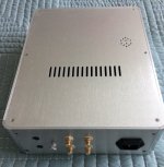
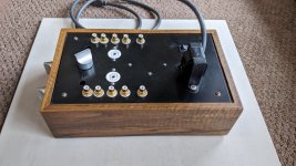
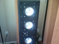
Hi all, so I'm now in the process of repairing a Marantz CD94, such an awesome CD player, I never had seen one in real life yet, they are probably among the best built players ever. I wish I owned one 🙄

Owner says it worked before but has stopped working, only reading very rarely a CD and not from the start.
Initial tests confirmed that player would be repairable (at least laser and all important parts of the CDM-1 tested ok so far - later I was able to confirm this - more on this follows).

Problem: when player is switched on, the swing arm does NOT come to innermost position, it stays in center balance position. If I put a CD, it tries to read it, but not from center, so no TOC, but from somewhere in middle and then the swing arm kind of "advances" randomy, trying to lock tracking, and most of times it gives up, sometimes it locks on one of outer tracks, trying to play.

I then confirmed via Service mode that there's a problem with the radial servo: it doesn't pass service position 0 and when I try to move the swing arm with the keys, it only goes to the outer extreme, it does NOT go to innermost extreme. Voltages are: 0,9V for the extreme that is working and 0V for the direction which is NOT working.

I then confirmed correct function of the swing arm by disconnecting connectors and applying safe low battery voltage directly to radial coil, it works fine, reversing polarity allows me to make it reach each extreme easily, it swings perfectly free also by hand.

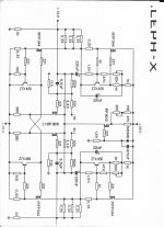
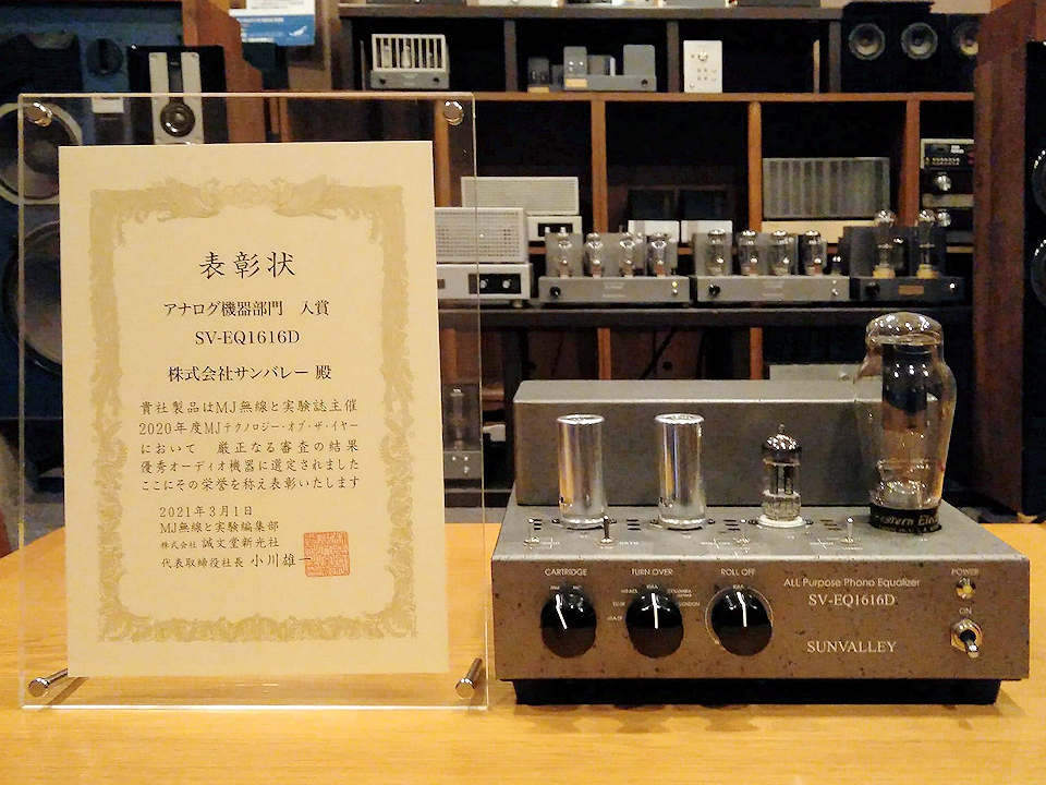
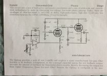
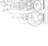
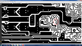
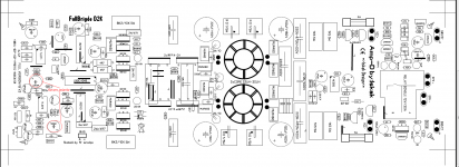
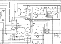
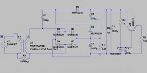
So, I read into service manual and noticed a test they suggest to check if radial servo output stage works: inject a 10Hz sine wave with 3V amplitude into service points 30 and 31 (schematic is attached below), which correspond to the opamp +- inputs of the radial out stage. This should make the swing arm "wobble" in both directions like it does when tracking. So, I did this and surprise: it not only did this well, but after removing the voltage, swing arm went to innermost position and TOC was read almost instantly! I hit Play and it played, perfectly! Music sounding without any flaws, I tried track forward and backward, all working, without a hitch, over the whole disc! BUT!!! Once I stopped playback and switched player off and back on, it was again malfunctioning! I injected again the 10Hz signal and once again it was working! But would stop working after seconds of not being used, wasn't even needed to switch off. Later I noticed that it would often NOT be able to make it to work with injecting the sine wave.

So, this is is very odd. The bright side of it is that it proves that all important components, especially the CDM-1, are absolutely fine. But it clearly shows it has a problem in radial servo circuit. I searched through all relevant threads on this forum and the internet. Nothing really.

Any ideas? Thanks in advance.

I'm planning to follow all signals mentioned in service manual for the section (service points) with oscilloscope, but I'm not sure what to look for.

Before I forget: regarding measurements, the above has to be completed: I measured the voltage of radial out while the player was in "working state" and it confirmed what I already knew: it now had the correct 0,9 and -0,9V for each extreme of swing arm when in service position 0 and the keys would be pressed (and yes, it moved to each extreme, obviously).
I also confirmed that all Power supply lines are correct. And that opamps of radial output stage get both supply voltages.

Any ideas would be great.

Some ideas I have regarding what it could be:
- the fact that injecting the voltage would change something, means that the problem probably lies close and directly connected to these points in the circuit, no?
- I suspected of a defective cap, which would be "charged" by this injection, so I changed the only cap directly connected to these points (C233), no change.
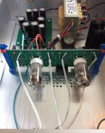
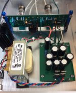
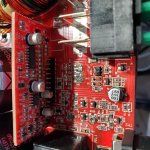
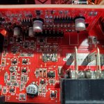
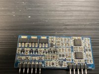
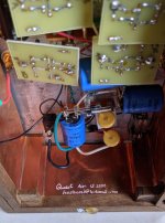
- I'm thinking about measuring around 4053. What's bad is that this particular player has this part of the circuit on a small piggy board with SMT components, making more difficult. This board actually shows some signs of oxidation/corrosion, so maybe bad soldering, defective components?
- I'm also thinking about checking the push-pull transistors in radial out stage.
- Maybe some passive component failed in radial out stage, not polarizing correctly towards one of the rails, making opamps not swing in that direction?

Just a few more info from a few tests I did: while the player is in non-working state, if I disconnect radial servo connector from CDM-1 preamp board and also the radial error signal disconnected, I can measure in service mode 0 +12V for the working extreme and on the other direction it makes the voltage slowly go down until it reaches zero. I guess it should go to -12V, right? Radial error signals from CDM-1 preamp board are fine, btw.

Attachments

  • Captura de ecrã de 2021-03-14 00-36-31.png
    Captura de ecrã de 2021-03-14 00-36-31.png
    298.1 KB · Views: 124

Infinity RS-8 Floorstanding Speaker modifications.

Hello,
I’m new to this forum and would like some opinions from some people that may have more knowledge on this subject. I have a pair of Infinity RS-8 floorstanding speakers that I recently purchased for $99. I can’t complain about the sound for the price that I paid. I currently have them ran off of a 90’s model Pioneer VSX-502 A/V Stereo Receiver. The speakers are made from a combo of a 1” dome tweeter up top, a 6 1/2” midrange, and a 8” side firing woofer. The towers are equipped with their own 100w amp for the woofers.
I pulled the two factory woofers out because they have fallen victim to the inevitable foam rot and were completely shot all the way around both speakers. I replaced the two with a pair of MTX road thunder entry level speakers. The 6 1/2” speakers seem to sound fine although one of the speakers is missing its dust cap. Not sure if that affects the performance at all.
Anyway, I’m wanting to improve and upgrade these towers. I’d like some suggestions on how to do this from speakers replacement to enclosure mods. I want to replace the two 8” woofer with something that is budget friendly but packs HiFi quality sound. I have thought about changing out the pair of Infinity 6 1/2” mids for something else.. the sound and quality of the infinity speakers are good but could I possibly get an even better sound and flatter response from a different type/brand? I’d do something with the 1” tweeters if possible.. a different material some tweeter or a horn style is something I’ve had in mind.

The two 100w amps in these towers produce plenty of power for them. I have used polyfill and packed the lower half of each tower to experiment with the sound effects it will have on the woofers. Any tips or suggestions would be highly appreciated. I’d like to keep this budget friendly as far as the speaker upgrades would go. As far as enclosure mods/crossover/other mods go I would be open to all suggestions. Whether they’re going to be free or cost me a few bucks. I want better sound out of my setup. I run these two towers in stereo mode and or “studio” mode on my receiver. I have two tears hooked up that come on in studio mode. They’re Bose Model 21’s and I’m not impressed with them at all but they work for a rear channel and giving me a better center image. Sorry for such a long post. Thanks in advanced.

I have included a few photos of the speakers just to give anyone an idea of what I’m working with. The two Bose speakers are no longer sitting on top of the infinity towers as this caused imaging problems for me.

Attachments

  • 94E33A74-C7D2-4DC0-ACD8-D65CA32187B5.jpg
    94E33A74-C7D2-4DC0-ACD8-D65CA32187B5.jpg
    884.7 KB · Views: 320
  • D8A1A6B2-7347-4A0F-A350-122C589429D9.jpeg
    D8A1A6B2-7347-4A0F-A350-122C589429D9.jpeg
    456.6 KB · Views: 343
  • 8430C808-1F1D-4354-840C-7CD1A5437A4E.jpeg
    8430C808-1F1D-4354-840C-7CD1A5437A4E.jpeg
    489.7 KB · Views: 380

NAD 314 dead right channel

Hi everybody,

Again, a newbie's question 🙂

I got myself an old NAD 314 amplifier, with a dead right channel, and I'd like to try fixing it.

With a source connected (on any channel), the right speaker is dead, but when I plug my earphones - I can hear on both sides.

Seems like the power amp section is good, since when i connect a source directly to the power-amp in sockets, both channels function well.

This leads me to believe that the problem is between the pre and the power amps, but I don't know how to trace it from here.

I have the service manual and schematics, but frankly - I'm lost. Any help / hint would be much aporeciated.

Thanks,

- Barak

Voltage doubler regulation

Hi all,
I thought to use as a supply for a small amp circuit a 22VAC single secondary (from a 50VA toroidal transformer) divided in two: one going to a standard diode bridge -> LM7824 and the other one to a half-wave voltage doubler -> transistorized zener regulator. The output voltage (regulated) are the first obviously 24V e the second 48.8V.
Based on some simple preliminary measuremement through a cheap DSO the resulted ripple on the second supply is 20mV, being I(L) about 10mA.
Since I'm interested in particular to this last one, is the ripple value acceptable or can I still improve it, obtaining a cleaner output? The other doubt is if I can have some trouble because of floating ground arising from the standard D.B. supply combined to the voltage doubler. Thanks.

Attachments

  • Vdoub.jpg
    Vdoub.jpg
    79.9 KB · Views: 167

Building the Zaph Audio ZA5.5tt - MMTMM 2.5-way Vertical Array

So I built the Zaph Audio ZA5.5tt. It was my first DIY speaker project.
Definitely the best speakers I've ever owned. Much better than the
Kevlar-coned Bowers & Wilkins that are built into the ceiling of my home
or the $1800 THX set I used to use for HT.

I'm surprised with the performance of these speakers. As far as clarity
of movie dialog, they outperform my headphones in A-B testing. Sure, I
wanted to have speakers but I thought that my headphones would still let
me hear dialog more intelligibly. I didn't expect that any speakers
would do that better than headphones. These speakers also have enough
bass for my music needs. I was concerned that I might still need to use
my subwoofer since the room is quite large(26 feet by 36 feet) but a sub
won't be necessary, so I can donate my old subwoofers to Good Will.

Reasons I picked the ZA5.5tt:
1. It was the lowest cost DIY product that gave me hope of having
performance I'd be happy with. Total cost of everything was
less than $600 for the pair.
2. John Krutke's posts and website gave me the feeling that we had
compatible engineering sensibilities.
3. It was the largest physical size speaker that I any hope of
having my wife accept in the living room. They are 8" wide. I
went with the ZA5.5tt instead of the ZA5.3 since the ZA5.5t uses
the same amount of floor footprint yet has twice the extra bass
radiating area.

What I learned:
1. Butt joints are fine. I make furniture with dowels and planned
to do that, but when I got out my dowel jig, I saw I was out of
dowels. Since the MDF cuts were fairly precision from the store,
I just used lots of clamps and tapped the MDF pieces into
position with a rubber mallet and then tighten the clamps.
Doweling would have been a waste of time.
2. It's OK not to buy the whole accessory kit from Madisound. I
bought just drivers/crossovers plus foam, port tubes and peglock
grill fasteners(wifey requires speaker grills though the design
is specified without them). The port tubes aren't flared and
require a good bit of time to remove the excessive casting flash,
but are convenient all the same. The Zaph design shows flares,
but computations suggested it might not be necessary. I did not
buy the $1.25/foot wire Madisound suggests. I used some 14 AWG
wire that the previous house owner used to wire some exterior
speakers near the Jacuzzi. I did not buy quick connects but
simply soldered directly to the speaker lugs. I shielded the
speakers from the process while soldering with sheets of paper.
3. I didn't need a plunge router. If the guide hole of the circular
jig I used was close fitting, I could plunge a stationary router
well enough by hand.
4. It's hard to get veneer perfect, but it's not too hard to get it
good enough even just using Tightbond wood glue. It's all about
getting the right amount of glue(too much causes wrinkling and
too little means fixing up all the edges). Despite that my taste
is solid wood, monolithic veneer is quite endearing. It was my
first experience doing veneer. Next time I might consider an
iron on glue. I was very happy with this source for raw
veneer: lepkowski of ebay.
5. 3M Super 77 is great for gluing the damping foam to the inside
of the cabinets.
6. Textured Rust-Oleum(#7220830) doesn't hide surface scratches. I
should have sanded and sealed before applying like I would have
done had I carefully read through John Krutke's advice on this.
7. Phasing the tweeter was confusing because I expected that I'd
have to reverse the phase because I thought it was a 2nd order
crossover. Anyway, they're wired in phase as the diagram
indicates. Ultimately, I just followed the directions carefully
and didn't try to out-smart the documentation. I did check the
woofer phasing -- all were correctly marked.
8. Using linseed oil finish on cherry veneer, it took 6 weeks total
time to let the oil cure between coats. Building my own
speakers took a lot of time, but I enjoyed it.

The final weight of the speakers is 59 lb each. I followed the enclosure
drawing best as I could, scaling the drawing for the port and internal
brace locations. I didn't fill the base with sand or kitty litter because
that is were I put the xovers, since the Madisound xover PC boards don't
both fit onto the bottom piece of MDF. Right now they're just resting on
dense felt pieces to protect the hardwood floor, but eventually I will
museum putty them to the floor for earthquake proofing.

Anyway, this is my first post, too. I found this group because I
sometimes Google LTspice to find how it is used(I'm the author of that
simulator). I'm contributing this post out of gratitude of the advice I
found looking through this forum. While this was my first DIY speaker
project, my wife tells me it's also my last, so I don't see that I'll
continue to be particularly active here.

Thanks are due to John Krutke for this awesome-performing speaker design.

--Mike

Attachments

  • GlueSqueezedOut.jpg
    GlueSqueezedOut.jpg
    209.8 KB · Views: 1,355
  • Baffles.jpg
    Baffles.jpg
    154.6 KB · Views: 1,308
  • Wiring.jpg
    Wiring.jpg
    230.8 KB · Views: 1,322
  • Final.jpg
    Final.jpg
    214.8 KB · Views: 1,589
  • CloseUp.jpg
    CloseUp.jpg
    192 KB · Views: 1,360

Need assistance selecting a step up transformer for ELS energizer, please kindly

Question regarding a step up transformer for ELS energizer, please kindly

Hello folks!

I've got a pair of Jecklin Floats coming from Germany, PS2 energizer - This is my first foray into the Float world, for better or worse, as repairs are needed (relatively confident I can handle it). I'm in the US.

I have a step-up transformer coming, but I'm wondering now...

To my knowledge, I shouldn't be worried about the cycles, as in effect, the energizer should actually run a bit better, with energy delivery to the caps a bit faster, less saturation in the transformer, etc, going from 50hz to 60hz...

Am I overlooking something in this regard? I don't believe there's anything in the energizer that would be affected by the cycle discrepancy, right? I'd assume going from 60hz to 50hz would be a cause of possible concern, not the other way around?

Best regards and thanks in advance!

6sn7 singles.

NOTE: BLACK TUNGSOL IS SOLD

Here are the rest of the decent tubes I tested.
$5.00 each plus shipping. $15.00 for shipping of any number in the states. Local pick up is also welcome. Zip code 07712
Thanks,
Evan

Attachments

  • CF18F9B7-3755-4644-860E-0D8B059F2F92.jpg
    CF18F9B7-3755-4644-860E-0D8B059F2F92.jpg
    993.3 KB · Views: 137
  • 3E7AE6A0-66B2-4A39-9C93-39751C8EE112.jpg
    3E7AE6A0-66B2-4A39-9C93-39751C8EE112.jpg
    991.9 KB · Views: 125
  • 59CA3876-ED74-49FC-A81D-C6A676AD8BE5.jpg
    59CA3876-ED74-49FC-A81D-C6A676AD8BE5.jpg
    991.4 KB · Views: 144
Projects by fanatics, for fanatics
Get answers and advice for everyone wanting to learn the art of audio.
Join the Community
507,801
Members
7,888,980
Messages

Filter

Forum Statistics

Threads
406,269
Messages
7,888,980
Members
507,801
Latest member
TMCK001