Hi all,
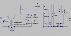
I thought to use as a supply for a small amp circuit a 22VAC single secondary (from a 50VA toroidal transformer) divided in two: one going to a standard diode bridge -> LM7824 and the other one to a half-wave voltage doubler -> transistorized zener regulator. The output voltage (regulated) are the first obviously 24V e the second 48.8V.
Based on some simple preliminary measuremement through a cheap DSO the resulted ripple on the second supply is 20mV, being I(L) about 10mA.
Since I'm interested in particular to this last one, is the ripple value acceptable or can I still improve it, obtaining a cleaner output? The other doubt is if I can have some trouble because of floating ground arising from the standard D.B. supply combined to the voltage doubler. Thanks.
Attachments
Try connecting the one point circuit ground at the D1 anode instead.
Add a 100R resistor between the positive terminal of C4 and C6.
Also split R4 in two, and add 100uF to ground at its center.
You could also increase both C3 and C4.
Add a 100R resistor between the positive terminal of C4 and C6.
Also split R4 in two, and add 100uF to ground at its center.
You could also increase both C3 and C4.
Last edited:
Thanks for suggestion, so you'd mean a RCRC filter inserted to improve the ripple. Me too I thought before to add a RC somewhere in the circuit.
As for the diode you mentioned, should I create a kind of star ground?
As for the diode you mentioned, should I create a kind of star ground?
The entire regulator circuit should float from ground, except for a single ground connection at the anode of D1.
The lower ends of R1 and C1 should go directly back to the diode bridge, with a wire from that point
going over to the quiet ground comprised of the anode of D1 and the lower ends of C2, C5, C6, and the load.
This keeps the rectifier charging current pulses away from the sensitive parts of the regulator.
Last edited: