The Gryphon class A power amp tech info needed

Hello,
I'm looking for service data of an old 1995 Antileon power amplifier, mainly the alignment procedure.
The schematic would be very welcome aswell. One of the channels takes a little bit longer to come up and I was told it's a common issue with alignment or replacement of certain part...but no one wants say which part.


Many thanks in advance. I am also willing to buy and pay for the schematics.


Regards,
Jan

Thought its about time..

Hi :wave: Thought its about time.. I joined.

Been popping in and out for quite some time looking at the forums. I'm interested in class D amps and about to under take a diy build. Previous projects, digital music player, mains distribution block and some speaker plinth bars (well I sent a drawing to a man and he made them).

Look forward to spending more time on here

Hi

Hi, I'm an old fogie, with a lifelong interest in audio, and a range of DIY projects. Despite this, my soldering skills leave a lot to be desired. I seem to spend forever fixing dry joints! I know there are "how to" videos on the web, but they do not seem to help.

A topic close to my heart is the multi-channel reproduction of conventional stereo recordings, and I will raise a separate thread on that subject...

pioneer A9 amplifier

Hello guys, I'm new here just want to know those have experience with the amplifier PIONEER A9... I replaced the main output transistors, but it keeps on short once the power is initiated... I replaced the complementary pairs 2SA1076/2SC2275 and all drive transistors connected to it, even coupled .47/5W resistors... still it burns out... anyone could give me some idea, is helpful...😉

Rockford fosgate punch 40.2 channel distortion

Hi all, I'm searching for help repairing my old school amplifier. After some minutes listening to music the left channel start to be terribly distorted causing me a lot of pain 🤣.
My board seams to be in good condition, I cleaned and restored the varistors with contact spray and degreased with isopropyl alcohol.

This is the scheme of the board. Hope you can help me, I'm so affectionate to my old school amplifiers! 🙂

Thanks in advance!

Attachments

Opinions on Clamping a ring-of-two bias-block in cathode of EL84

Ive been modifying an amp that uses P-P EL84. Ive made a couple of bias-blocks (CCS sub-circuits) along the lines used by Gingertube in his Baby-Huey amp, one per output valve.

Due to the high +B in this amp, Ive reduced bias on the EL84 to 30mA which equals 10.5W per tube at its current +B.

During static testing, I noticed a loss of power over what I had before, so checked cathode-voltages. These (at point of clip) were 25V. The idle voltage was 12.5 to 13V depending on which tube checked.

Ive placed a 14V 5W Zener diode clamp across the bias-block from tube cathode to deck. This has restored the power at full output to near what it was....

Thoughts....?

Distortion sim of Opamp and simple JFET

Pass LabsAudio distortion and feedback - Pass Labs
The link above from Pass Labs say that high-gain NFB (such as Opamps) has lower distortions overall but the output harmonics are more complicated.

A simple triod although has high distortion but mostly 2nd and 3rd order.

I did two simulations using opamp and a simle JFET common emitter and the simulations show that: Opamp has lower overall distortions but it has more harmonics on the output.

On the IMD plot two 10Khz and 11KHz, there is only a single 1KHz on the simple FET, but on the opamp, there are several overtone of the 1KHz tone.

Because of that, opamp tends to sound lean and brittle due to the higher order harmonic.

The harmonic content of an overdriven tube amplifier consists primarily of 2nd order and 3rd order harmonics with some 4th order harmonics. The harmonic content of an overdriven transistor amplifier is primarily 3rd order with suppressed 2nd order harmonics. 2nd and 3rd order harmonics are the most important from a viewpoint of electronic distortion. Musically the 2nd harmonic is an octave above the fundamental and is almost inaudible, yet it adds body to the sound, making it fuller. The 3rd harmonic is a musical 12th. Instead of making the tone fuller, a strong 3rd harmonic makes the tone softer. The odd harmonics (3rd, 5th, etc.) produce a "stopped" or "covered" sound. The even harmonics (2nd, 4th, etc.) produce a "choral" or "singing" sound. Adding a 5th to a strong 3rd harmonic give the sound a metallic quality that gets annoying in character as the amplitude increases. A strong 2nd with a strong 3rd harmonic tends to open the "covered" effect. Adding the 4th and 5th harmonics to this gives an "open horn" character. The higher harmonics, above the 7th, give the tone "edge" or "bite."

Attachments

  • Untitled3.png
    Untitled3.png
    383.5 KB · Views: 133
  • Untitled4.png
    Untitled4.png
    306.6 KB · Views: 133
  • Untitled5.png
    Untitled5.png
    318.8 KB · Views: 131
  • Untitled6.png
    Untitled6.png
    306.4 KB · Views: 130

new mic design again

My latest in mic design, the element is an actual mic element, originally I wanted to mount it on some wood but found myself with some blue plastic cutting boards, so I decided to use them instead, the element is mounted on an old tweeter escutcheon connected to the plastic through some hair elastics.I added some gold trim just for looks.
Imgur: The magic of the Internet

Beyma 12CXA400Nd 12" Coaxial speaker drivers

For sale are a pair of good condition Beyma 12CXA400Nd 12" coaxial speaker drivers.

Matched pair. Beyma prototype units that were tested before they were given the OK to start going to production.

One driver has bit of damage at edge of frame (see photo) but has been repaired. No effect on structural integrity or performance of unit.


Specs and measurements here:
Beyma Speakers - Beyma 12CXA400Nd lighweight neodymium 12" coaxial speaker - Beyma 12CXA400Nd 12" coaxial handles a powerful 400 watts AES. Beyma 12CXA400Nd 12" coaxial is extremely sound and warm sounding.
Test Bench - Acustica Beyma’s 12CXA400Nd 12” Pro Sound Coaxial Driver | audioXpress

Looking for $800 AUD + postage.

Cheers!

Attachments

  • image1 (2).jpeg
    image1 (2).jpeg
    508.8 KB · Views: 374
  • image2 (1).jpeg
    image2 (1).jpeg
    609.1 KB · Views: 354
  • image3 (1).jpeg
    image3 (1).jpeg
    746.5 KB · Views: 351
  • image4.jpeg
    image4.jpeg
    667.6 KB · Views: 337
  • image5.jpeg
    image5.jpeg
    756.8 KB · Views: 338
  • image6.jpeg
    image6.jpeg
    588.7 KB · Views: 138
  • image7.jpeg
    image7.jpeg
    660.5 KB · Views: 166
  • Image-1.jpg
    Image-1.jpg
    187.8 KB · Views: 158

MTM with TC9fd

here is just a suggestion, an alternative to Nola Brio Trio, or Mini Karlsonator with Dual TC9fd-18-08...

I built NOLA Brio Trio, just in foam core, and just for fun. While it played ok with the sub, ultimately, I did not like two things:
first, two tweeters in a sense, as one is run fullrange, one with high pass, still, both project heights...I do not like that
second, while TC9fd is performing well in midrange area, and may be extended to the heights, when it comes to of axis, it starts beaming terribly from about 5kHz. Just look at of axis response.

So I converted Nola Brio Trio to typical MTM with small Dayton dome. Quick and dirty crossover, measurement and listening lead to an amazing sounding neutral speaker. I have not saved the measurements, but it was exceptionally flat. I may redo the measurements once I paint the foam core.
If you need HiFi bookshelf, built this one...
If you run it from 150Hz with sub, you will love it.

Attachments

  • TC9fd MTM.png
    TC9fd MTM.png
    12.6 KB · Views: 3,717

AMB sigma11, Pete Millett Cap Board w/ Caps

Hi all,

(*) 2x AMB sigma11.
one configured for 5V output
one configured for 24V output

Obviously this can be changed to any voltage with a resistor and/or zener change.

Asking $40 each includes US shipping.

(*) Unused Pete Millett Snap-in mounting board mounted with CDE 380LX 10mF 35V.

$15 shipped.

Attachments

  • 2021-03-14 15.16.56.jpg
    2021-03-14 15.16.56.jpg
    213.2 KB · Views: 319
  • 2021-03-14 15.16.49.jpg
    2021-03-14 15.16.49.jpg
    274 KB · Views: 315
  • 2021-03-14 15.17.06.jpg
    2021-03-14 15.17.06.jpg
    212.3 KB · Views: 312
  • 2021-03-14 15.17.14.jpg
    2021-03-14 15.17.14.jpg
    221.5 KB · Views: 306

How to add pics to post?

Would someone be kind enough to tell me how to add pics to posts. I went to FQA which said this.

"As a member, you can create Albums of images that are linked to your public profile. Albums can be created by visiting the User Control Panel, and clicking on the 'Pictures & Albums' link, and then clicking on 'Add Album'."

I have no pictures and album link under user control panel.

Thanks

Air core inductors

I’m upgrading my crossovers in some old Klipsch speakers
One inductor needs to be 2.5mH
What I have are some 1.5mH and 1.0mH
These are Flat copper foil inductors
I found a way of hooking and lining them up in a way to get the 2.5mH that’s needed
I know with caps you can do this, but is this ok with inductors ?
One will lay flat and the other ( smaller ) will be sitting on top of the flat one, right in the open hole of the larger coil
I’ve tested these with 3 different lcr meters and they all show the same readings of 2.5mH.
So any ideas of if this is ok or if it’s not ok, why ?
Thanks

Project with high power

Hello to everyone,I work more than 20 years in club, but now in this pandemic I stop working and the loud sound miss me a lot.
I need help to make, high power speakers and I hope to help me to choose best drivers for this.
I have home speakers which is not enough for me, I want power like in the club, but I dont want to buy some ugly PA spekers for my living room and for that I decide to ask here for help to boyld towwer spekers.
I love to work with wood, but will need help for choosing the drivers and filters!
I thinking for 2x15 inch for bass in each cabinet and i hope this will be enough for room of 50 square meters!
I prefer good deep bass and with good detail mids and highs!
I hope to fit in budget for drivers around 1000-1200 euro and I hope to can find the drivers here in Europe!

I will be grateful for your help 🙂

Strange (to me) Sine Wave

I'm getting familiar with my oscilloscope and audio generator so I fed a sine wave directly to the o-scope and it looks as expected. I then fed the signal into the aux input of a late 1960's solid state integrated amp and this is what I get...

sherwood amp.JPG

The amp works although it has all of the original components. I tested for DC at the speaker terminals prior to hooking it up to the oscilloscope and there was around .01 volts each channel.

Any idea what would cause this type of signal?

building my first pass A3 clone

Hi all,

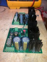
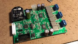
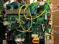
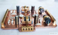
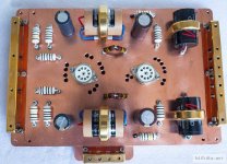
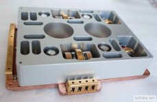
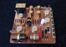
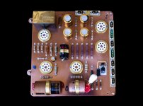
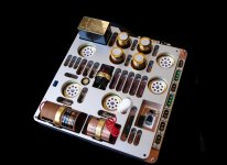
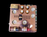
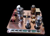
i like to build me a pass A3 amp, but i have so many questions, i did buy some nice pcb's.
And i have some stuff lying around what i like to use if it's suitable for the amplifier, so i can keep the cost down for the build.
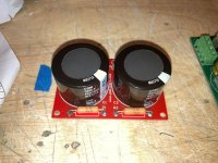
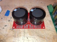
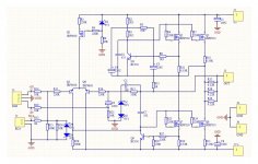
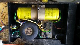
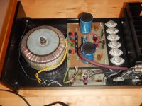
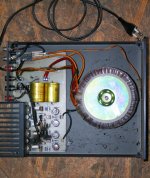
First starting out with the supply i have a 500va with 2x18v ac out, and a 500va with 2x24v ac out, can i use them and which is better to use with the A3 amp, i believe the original power supply to have is a 2x20v ac out.

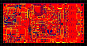
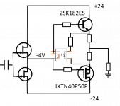
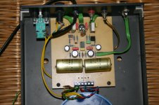
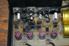
Next i did see that in my schematic diagram i did get from the seller of the pcb's i did see that they use the bc550c, and i did see in the Aleph 3 Service Manual that they did use the mpsa18 so i did saw that they did have lower distortion and more hfe so i did order them.

Than i have some new mosfets lying around, again in the original Aleph 3 Service Manual they did use the irf244 i do not have them, i have the irfp250 that are used in my clone A3 schematic diagram and i have the irfp260 also, what must i do, buy the irf244 or go for the irfp250 or the irfp260 what i already have.
I believe the irfp260 has the lowest resistance, does the resistance matter or not in a amp, oke so where i have to look for in a mosfet for a amplifier, what is important to look for.

So next i have some new Panasonic caps lying around, the FR version, so fast and a long life span, they are just the value i need 220Uf, can i use them or do i need real audio caps for this amp.

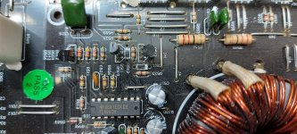
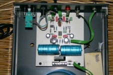
I did build a Hood 1969 amp before so normal u set the middle voltage with a pot and the bias with a pot, i do not see them with this design, so i am sure that they are resistors that do that job, but i do not now which resistors i have to change, but i think i need to change them with i higher or lower voltage on the rails.

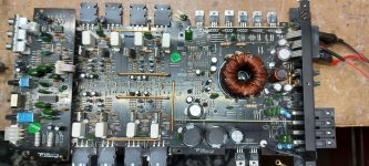
please understand i am a beginner at this, so please do not judge me for not knowing, i did build so many other things, but only ones i did build a small amplifier, and i did like the sound of that Hood 1969 with the toshiba 2sc5200 in it, i did build that amp for in my jukebox diy project.
And yes i do like nice music, who doesn't, so i do build my own speakers, but this amp is the next step up, building your own amp, so i need help to do it.
And i hope i get it here.

O yea i did hear a few years ago a original Pass Amp, i can not remember what type of Pass amp that was but i did like it, i did not forget the nice sound, i hope my Pass clone amp will get the same sound, or near to the original sound, but for the real thing i do not have the money so that's why i go this way of building my own Pass clone amp and hope for the best.

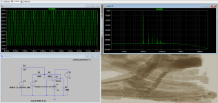
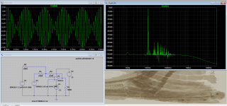
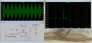
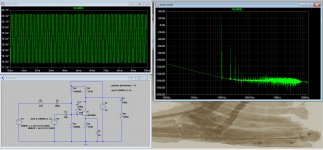
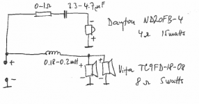
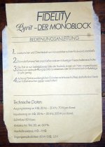
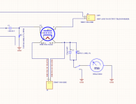
i ad my schematic diagram i did get from the seller of the PCB's

Attachments

  • passA3.jpg
    passA3.jpg
    148.6 KB · Views: 1,983

What is wrong with this driver?

Its a pair of Seas FA22

H1597-08 FA22RCZ

One of them has a significant dropp in frequency in the upper range.

The measure equal re (Ohm) and le (with a LCR-measurement)

Please look in the link to the forum thread under:

The first measurements is in the cabinet with correction filter (baffle step & notch)

The latter is measured outside the cabinett close to the driver without any component


Noen som vet hvorfor? | Hifisentralen

Help, power supply for tpa3251-4ch-100w 3e Audio

Hi All, please help,

What would be a good power supply match that is readily available (in US) to buy for my 3e Audio TPA3251 4x100W 4Ch Class D Audio Amplifier board?

The Data sheet says: "Single supply voltage range 24V~36V(UVP:24V)" with note,
"*PVDD can higher to 36V but depend on full output power and thermal condition,30V is recommended in this design"

Web page:
TPA3251-4CH-100W | 3e Audio
data sheet:
http://www.3e-audio.com/wp-content/uploads/2018/07/DS_EAUMT-0100-4-A_Rev1.0.pdf

Thank you,
Steve

Spectral DMS-10 Dual 24V Power Supply for DMC-10 Preamp

Hello, I found this DMS-10 in an old Volvo I was parting out a couple years back. I came across it again while cleaning out - and I'm looking to find it a home.
The front LCD doesn't turn on, but there is life! I tested the outputs with an oscilloscope and found various ~24v waveforms.
The unit is a little banged up, some scratches and dings on the aluminum case.
I'm new here and not much of an audio enthusiast myself, but I have seen how much a DMC-10 combo can go for... :Popworm:
Considering the condition and niche market I'd be willing to accept as much as someone is willing to pay for it, and at the end of the day I just want to see it go to use one way or another.
I was considering keeping it as a power supply to build a DIY analog synth sometime in the future...
But I've seen a thread here where someone was missing their DMC10 power supply and ended up using two separate 24v power supplies and made it work... but I figured someone may want the original thing 😉


Various readings from o-scope:
(Had it plugged into power inverter - not true sine, not sure if this affects the waveform, or what would be normal, or whether I actually squared up the wave on the scope to get an accurate V/AC reading, or which pins I should have been checking between so I tried all combinations :smash:
But at least it shows that something is going on in there :spin:)


Power supply screw terminal capacitor replacement with small modern caps?

I bought this Exposure 6 power supply at a yard sale a couple of years ago for $20. It was built in the mid 1980's and the fellow I bought it from said he had measured high ESR on the capacitors which he thought were dried out. The caps. are 10,000uf, 63volt and are screw terminal type and quite large. I have a few new Cornell Dubilier 10Kuf, 63 volt through hole caps. that are tiny compared to the originals and I am wondering if there is any downside to using them as replacements?

Thanks for any info.

Attachments

  • POWER SUPL;Y.jpg
    POWER SUPL;Y.jpg
    615.3 KB · Views: 166

RF P300-1 power supply

Have a Fosgate on the bench, came in with blown pair of PS FETs. Replaced those, the gate resistors and driver transistors, but still has an odd symptom- scoping the drain leg of the FETs reveals a sine wave not a square wave.

With the drivers removed I’m getting good square waves from the 494 so that’s still good, and the PNP side of the totem has good continuity to ground. What resistance should the NPN drivers have to B+ though? I would have expected 10-100 ohms or something like that, but it just keeps counting up like it’s charging a cap somewhere.

2.1 DSP Amp born of frustration

Hello everyone,

So I thought I'd share a project i've been working on because I feel that you guys may have opinions and comments which might make me realise i've wasted many months of my life! I've been a great fan of making my own portable speaker systems over the years but I have always found the market offerings for the amplifiers, bluetooth modules and DSPs either too low a quality or not integrated/controllable enough.

For one example the Sure JAB Boards seem great on paper, but after implementing them i've been left with odd bluetooth clicks and pops, bad gain structuring and difficulty controlling them in more than just a basic way. Also the provided indicator LEDs are crap for various reasons. There are many other systems I have tried and can report similar findings.

I wanted a board that can accept bluetooth (4.2/APT-x) and line in, signal process it in any way necessary and split it out to 2.1 (or 4) amplifier channels. All the while the board needs to manage its battery pack, charging and user interface (i.e Pots, LEDs).

I toyed with the idea of using TI's amplifier chips with integrated DSP, but I love the ADAU1701 & SigmaStudio and I am not aware of a DSP/Amp combo IC that has a 2.1 channel mode. For this reason my current design uses analogue input TPA3116D2s, one operating in PBTL mode. Another revision exists which outputs to 4 channels. The bluetooth is received with a CSR BTM625 module, sending audio to the DSP via an I2S bus. The bluetooth module is also designed to be fully user configureable.

Control and indicator LEDs are handled by spare GPO pins on the ADAU1701. It's stretching what this chip can do but I decided that including a microcontroller which could instruct the DSP could cause too many programming issues for the end user. Keeping all the programming in Sigmastudio's visual interface was a design goal.

The system is designed for a 4S LiPo battery, and can plug straight into any RC style battery via its balance connector. Off the shelf battery management boards (BMS) always seem to under and/or over charge the cells so I wanted to manage that on my board as well to keep things simple and safe. I have two board versions, one with an external BMS and charge controller and one with it integrated. The charge controller is robust and takes 19-28VDC.

I really like the idea of somebody picking up one of these boards, an appropriate battery, a few speakers and that it essentially all the electronic hardware that is required to build a great boom box with everything down to the turn on beep customisable. I suppose I am posting this here now as I have been working on this a long time and I wanted to see if you guys think i'm barking up the wrong tree. Is this something you would use?

Photos include a couple of the prototypes of the 'split' battery management and amp/DSP boards (which after a lot of bodge wires are working really well) and a screenshot of the integrated layout. The prototype boards in the images are using a TinySine APT-X bluetooth receiver, but this has now been changed to using a CSR module on the board.

Cheers! 😱

Edd

Attachments

  • Screenshot 2019-01-10 at 20.51.29.png
    Screenshot 2019-01-10 at 20.51.29.png
    262.3 KB · Views: 1,105
  • f2d21a10-4d1f-4982-bb8a-27112a8bded1.JPG
    f2d21a10-4d1f-4982-bb8a-27112a8bded1.JPG
    273.4 KB · Views: 1,079
  • IMG_6268.jpg
    IMG_6268.jpg
    1,022 KB · Views: 1,099

Hypex Ncore NC502MP OEM amp module

500WPC 2 channel Ncore amp module

Hypex Electronics B.V.

With the OEM evaluation board

Hypex Electronics B.V.

Killer little amp. Solid clean power. $350 firm for both.

I’m pretty sure this is the cheapest turnkey amp using the module

VTV AMPLIFIER Stereo Hypex NC502MP NCore Amplifier 500WX2 | VTV Amplifier

It uses a Ghent case with custom machining on the front panel. Buy the same case here:

ghentaudio --- DIY Stereo Case-Kit for Hypex NC502MP

And with 15 minutes of your time you’ll have the same thing for $150 cheaper.

Phoenix Gold Ryval V754

Good afternoon

Can anyone please tell me exactly what diode(s) belong in location D510 and 511? The 494 is making drive waves... but nothing on the gates of the transistors. Went to look at the driver transistors and noticed these 2 have been removed from the board.

Thanks in advance!!

Attachments

  • 20210328_122138.jpg
    20210328_122138.jpg
    1 MB · Views: 55
  • 20210328_122127.jpg
    20210328_122127.jpg
    1,013.8 KB · Views: 67

  • Locked
The perfect combination of sound and craftsmanship

In my spare time for two years, I DIY the power module and amplifier module of the tube preamplifier
Amplification module
935888d1616768607-perfect-combination-sound-craftsmanship-012445a9yzltb357dch7vc-jpg

935889d1616768607-perfect-combination-sound-craftsmanship-012446k8jjx3x33zj47gmx-jpg

935890d1616768607-perfect-combination-sound-craftsmanship-012835yvquyt3smcppquzu-jpg

935891d1616768607-perfect-combination-sound-craftsmanship-013256v1q2j7q1d1ajfgjr-jpg

Power module

Attachments

  • 012445a9yzltb357dch7vc.jpg
    012445a9yzltb357dch7vc.jpg
    83.3 KB · Views: 1,397
  • 012446k8jjx3x33zj47gmx.jpg
    012446k8jjx3x33zj47gmx.jpg
    120.2 KB · Views: 960
  • 012835yvquyt3smcppquzu.jpg
    012835yvquyt3smcppquzu.jpg
    68.2 KB · Views: 978
  • 013256v1q2j7q1d1ajfgjr.jpg
    013256v1q2j7q1d1ajfgjr.jpg
    70.2 KB · Views: 975
  • IMG_6902.jpg
    IMG_6902.jpg
    409.6 KB · Views: 217
  • IMG_6903.jpg
    IMG_6903.jpg
    244.7 KB · Views: 237
  • IMG_6905.jpg
    IMG_6905.jpg
    764.8 KB · Views: 300
  • IMG_6907.jpg
    IMG_6907.jpg
    575.7 KB · Views: 319
  • IMG_6911.jpg
    IMG_6911.jpg
    486 KB · Views: 265
  • IMG_6916.jpg
    IMG_6916.jpg
    476.2 KB · Views: 284

FS: Box o' preamp parts

SOLD!


Started a preamp project then went in a different direction. Asking $100US for the whole box, shipped to your door. Canada/US sale only please. Paypal works best.

In the box:
2 Glassware Aikido Cathode Follower buffers built up for 12AU7s. Includes the extra supplied resistors for other tube types (12BH7, ECC99) - ACF 12Vac Tube Stereo Buffer
2 x JJ ECC82
4 x JJ ECC802S
4 x Tung-Sol 12AU7W (re-issues if you want to call them that)
1 x Glassware grounding board
3 x snazzy 1-1/4" dia. knobs from B&K old stock
1 x chassis IEC plug w/ fuses
a whole passel of hookup wire
1 can - Deoxit D5 contact cleaner

So, yeah, asking for $100US for the whole kit and caboodle. Or hell, make me an offer. You never know.
-tom

Attachments

  • IMG_2669.jpg
    IMG_2669.jpg
    979.8 KB · Views: 296

Minimum acceptable AWG for Inductors on Crossover build?

Hi.

I'm exploring the choice of Inductors for a crossover build.
It's a 3 way Loudspeaker design needing 0.18mH, 0.39mH, 0.56mH, & 1.5mH Inductors in each box.

To keep the build cost down is 20 AWG acceptable, or will it compromise sound reproduction compared to 18 AWG?

A cost comparison from a couple of local suppliers:
All Inductors 18AWG (+ - 3% Jantzen) = AUD$141 vs
All Inductors 18AWG but the 1.5 mH Inductor is 20AWG (200watts + - 5% Dai Ichi) = AUD$96

Speakers are 12" Woofer, Horn Midrange, & Tweeter.
6 ohm Impedance.
100 W RMS DIN.
95Db.

Crossover frequencies:
Woofer to Midrange 1.2 kHz to 2 kHz
Midrange to Tweeter 5 kHz to 10 kHz

cheers


Cliff

2.1 class D amp + DSP

Hi everybody !

I'm planning to build a transportable bluetooth speaker (15 kg max) that I could use for little parties. I want it to be battery powered, and to use a DSP. As I want to use 2 x 6.5" woofers and 2 tweeters, I would want to use a 2.1 system and I saw in a video (How To Build An Audio System With Bluetooth & DSP Integrated - YouTube) that I could use a mono JAB3-100 + a stereo JAB2-30 class D amps to make my 2.1 system. My biggest concern was to know how to power everything, and in the video they use a Wondom 18650 Battery Balance and Protection Extension Board, and it would be great for me as it seems to be quite easy to setup, and it makes it easy to power my amps. I can even connect 2 of these battery boards to have a bigger capacity. My question is : do someone have already tried this setup ? Does it work properly ?

I'm also thinking that maybe it would be easier to have one 2.1 amp instead of two different amps to make my 2.1 system, but I don't think there exists this type of amp with integrated DSP. But maybe the best solution would be to have a 2.1 amp + a DSP board next to it ?

I would love to have feedback on your personal experience, if you think the JAB boards setup is a good solution, or if you have better solutions...
I put the links of the JAB boards + battery charger if you want to check

PS : i'm a beginner in electronics, but I have knowledge about DSP (Sigma studio, ...)

JAB2-30 class D amp : WONDOM AA-JA32472 JAB 2-30 V4 Module Amplificateur Stereo Class D 2x30W 8 Ohm Bluetooth 4.0 et Antenne - Audiophonics

JAB3-100 class D amp : WONDOM AA-JA31181 JAB 3-100 Module Amplificateur Class D avec DSP Mono 1x100W - Audiophonics

Wondom 18650 battery charger : WONDOM AA-JA11113 Chargeur Batterie 18650 pour Amplificateur JAB 2 15 / 24V DC - Audiophonics

Current Name from German's former Company "Fidelity" and where are the Schematics ??

Current Name from German's former Company "Fidelity" and where are the Schematics ??

This company, known only to insider circles, mainly produced integrated-, pre- and power amplifiers.
Until this day I haven't heard them unfortunately, but this devices have a very good reputation concerning sonic quality.
Test reviews I have found in German's magazine stereoplay 1985, oct. (GARANT, integr. amp), 1986, aug. (OPAL preamp)

Who took over this audio brand and who can upload the schematics ?

Best thanks for some hints.

This are not the currently brands (nonetheless, they are also very interesting audio products):
Power Supplies, Filters, Clocks, Upgrades, Low Noise, Hifi
Musical Fidelity | World-Class Manufacturer of Award Winning Amplifiers, CD Players, DACs and Digital Audio Devices (UK)
Fidelity Acoustics (Vancouver, BC, CDN)
Ikeda – IBEX AUDIO (formerly Fidelity Research)
Osawa-Fidelix - mentioned under
LN-1 FIDELIX - HiFi-Do McIntosh/JBL/audio-technica/Jeff Rowland/Accuphase
https://www.cjm-audio.de/history-verkauft/fidelix/
http://www.fidelix.jp/others/cartridge.html
http://www.fidelix.jp/products/LIRICO/index.html
http://www.fidelix.jp/technology/cartridge3.html
http://www.hifimuseum.de/vor-vorverstrker-1982-teil1.html

In the attachment some images from the power amp models TOPAS, PYRIT and Crysolith

Attachments

  • Fidelity Power Amp Model Pyrit Front.jpg
    Fidelity Power Amp Model Pyrit Front.jpg
    259 KB · Views: 581
  • Fidelity Power Amp Model Pyrit Mains Transformer.jpg
    Fidelity Power Amp Model Pyrit Mains Transformer.jpg
    306.1 KB · Views: 526
  • Fidelity Power Amp Model Pyrit Owner's Manual.jpg
    Fidelity Power Amp Model Pyrit Owner's Manual.jpg
    652.2 KB · Views: 504
  • Fidelity Power Amp Model Pyrit top view-I.jpg
    Fidelity Power Amp Model Pyrit top view-I.jpg
    331.5 KB · Views: 518
  • Fidelity Power Amp Model Pyrit top view-II.jpg
    Fidelity Power Amp Model Pyrit top view-II.jpg
    332.5 KB · Views: 511
  • Fidelity Power Amp Sarder top view PCB Stereoplay 4-87.jpg
    Fidelity Power Amp Sarder top view PCB Stereoplay 4-87.jpg
    534.6 KB · Views: 481
  • Fidelity Power Amp Topas top view PCB-I.jpg
    Fidelity Power Amp Topas top view PCB-I.jpg
    748.9 KB · Views: 420
  • Fidelity Power Amp Topas top view PCB-II.jpg
    Fidelity Power Amp Topas top view PCB-II.jpg
    657.2 KB · Views: 397
  • Fidelity Power Amp Topas top view PCB-III.jpg
    Fidelity Power Amp Topas top view PCB-III.jpg
    142.8 KB · Views: 377
  • Fidelity Power Amp Crysolith open.jpg
    Fidelity Power Amp Crysolith open.jpg
    233.2 KB · Views: 366

Dead Onkyo tx-sr500e (newbie's question)

Hi everybody,

After your great help with the nad 314, I got some appetite and got myself a new challenge: a dead Onkyo tx-sr500e.
The receiver is totally dead. I plug it in, power it on, but nothing happens: no display, no led, no relay-clicking. Absolutely nothing.
Naturally, the first suspect was the power supply.
The fuses are ok, and there is no visible sign of blown components.
I noticed a small transformer on the power board (in addition to the big transformer which I believe supplies the power to the analog section)
Is it possible that there is a "secondary" power supply (switching power supply?) for running the digital electronics? If so - is it reasonable to assume that this switching power supply is faulty?
Where should I look? I'm kinda scared to start poking my multimeter in the 220V area 🙂

Any help/clue would be much appreciated.

Thanks,

- Barak

Is anyone familiar with Nokia drivers?

Hello good friends,

A friend gave me those two nokia 8inch midbass drivers. They are made in Germany and to be honest they sound good, free air with no crossover attached.
Does anyone have any info on those drivers? Are they supposed to be good? Worth giving a try?

Attachments

  • IMG_20210326_141803.jpg
    IMG_20210326_141803.jpg
    650.5 KB · Views: 155
  • IMG_20210326_141807_1.jpg
    IMG_20210326_141807_1.jpg
    582 KB · Views: 157

Mordaunt Short Signifer

Hi, I wonder if any of you fellow DIY members have Modaunt Short Signifers or any tech details of their x-over.
I am in the process of bringing a pair back to life, but I think the modified/upgraded/ semi submerged in adhesive, hardwired x-over is incorrectly wired. The problem seems to be centred around the mid-hf part of xover. It appears to have a 4th order filter for hf section, but the way it's presently wired it has a 3.3uF in each half of the 4th order network. I have scoured the net and can not find any 4th order networks that replicate this, ie, butterworth, linkwitz etc. There is also a 6.8uf capacitor that is presently wired in the midrange roll of section of x-over, which I suspect should really be in 2nd half of high pass filter and the 3.3uF should be where the 6.8 has been wired.This would be more in line with what I have seen in most schematics. The units are nominal 8-ohms and xover frequency 5K.

Opinions, info, would be very much appreciated.

Recomendation for mid range SE ...

Im know this is a subjective and dangerously contentious question.

Im looking to find out what you consider the best SE integrated tube amp under 4K. I only want a SE amp, would like to have UL/Triode option. High on the list, Point to point as much as possible.


Im looking at PrimaLuna, (Like the option of being able to choose between many types of tubes) Line Magnetic (although difficult to find, cant get US distributor to respond).


What I dont want is to buy amp after amp after amp sloooowly working towards what I hope to hear. Figure 4K should keep me happy long enough...

Sugden A21a...hummy

Hi All,

about one year ago I bought a 2nd hand Sugden A21a power amp circa 1999.
I used it with great pleasure for about 6 months with a pair of Davis Acoustics bookshelfs. Then I moved it to my main set with two big Tannoy Gold and...hum! Hum on both channels, with right worse than left. Thought something went faulty during moving but, connecting Davis back and with my ear stuck against the woofer, the hum was there! The difference in sensitivity made a so big difference in revelaing background hum noise.

Ordered a new set of capacitors for the A21a, all of medium-to-high quality, all Rubycon as the original, except for the four big 10000uF which are RS rebranded Cehmicon, but with 105°C max temp, instead of original 85°. I opted for all 105° because of the very high temperature reached inside the Sugdy. This A-class power amp is one of those audio devices that asks for new capacitors each few years if you keep it on many hours a day...

Once the capacitors arrived I recapped the two twin PCBs. Not a so big effort, the Sugden design is simple and disassembling was quite straightforward.
I also checked the BIAS current that should be 1,1 A thru fuse and perfectly tuned it with the single available trimmer.

Ok, work done, powered it up...damn! The right channel is less but still hummy, being the left now perfectly silent! 🙁
Half a day audition, not only confirms that right hum will be always there but even that, when everything is at regime temperature, the overall sound quality definitely improved. On the big Tannoys now the bass is way better controlled than before recapping. In complex I hear something more sweet and defined than before. If only the hum was not there...

So my request to the community: where should I look to identify the hum source?
It is not an air catched one, since internal signal cables from RCAs to boards are of the same lenght and in perfect shape. Even short circuiting inputs the hum is unaffected. Changing signal cable path or position inside the case does not affect that noise, nor touching caps or resistors with fingers/metallic screwdrivers.
It is defintely something in the circuit topology, but what and where? :scratch:

Before starting replacing film capacitors too, I would like to know your opinion on this. I do not even own a schematics, which is not easy to be found on the net.

Thank you

Have a nice day

Raf

P.S.
Of course, writing emails to Sugden resulted in an absolute silence... :ghost:

1626 Darling monobloc - unexpectedly low B+ voltage when choke loaded

Hello, and let me introduce myself. My name's Mike and I have been following people's experiences on this forum for years. As with so many people, now my kids are (much) older, I have finally got around to using some of the tubes, chassis, iron and components that I've been stashing away for the last 20 years and have restarted my DIY audio journey 🙂

I decided (as I find myself in the process of evolving/swapping out DIY speakers and have only one completed at the moment) to start with a pair of mono 1626, or Darling derivatives.

So I designed the power supply (using PSUD2) to have a HT voltage of 266v under the 37mA load that the tubes will present to the supply. The input tube is a 12J5GT, to allow a single heater winding. The rectifier tube is a 5Y3GT (separate 5v filament winding), to get the voltage down to the level I need with my 520v CT PT without heating up too much resistance in the filtering network.

I decided to go with C(low)LCRCRC. Basically a 2uf cap followed by a 12H choke, then three 15uF motor run caps along with two 150 Ohm resistors and it did indeed work out to the voltage I was expecting when I built the amp into a steel Hammond chassis.


I powered the amp up and the two 12.6v heater tubes didn't light up, so I measured the heater V and found it to be zero because I had wired the two series secondary 6.3v windings out of phase. So, wiring corrected, I powered it up again and all was well. No hum to speak of either!

I measured all the voltages around the circuit (cathode bias V for each stage and plate V on the tubes etc.), and these were bang on what I intended. I started to listen to some music, it sounded great. But, after about twenty minutes I noticed a smell in the room and went over to check out the amp and noticed smoke coming from the power transformer! I shut the amp down and disconnected and removed the transformer and put it outside overnight to get rid of the smell (R-Core PT so lots of plastic tape). When I came to check it out in the morning I discovered that the insulation was melted and burnt on the secondary, and I'm wondering if this is because of the fact that I wired the heater windings out of phase and ran the amp to test voltages for maybe 10 mins?

I had in my stash another similar transformer with a higher secondary voltage (0-360v x 2 windings @100mA) and also 5v/2x6.3v windings, same mounting hole spacing - woohoo! So I figured I'd modify the power supply by removing the first cap and making it choke loaded (Hammond 193 series) to get the volts down to the same level as using the original PT. I removed the second 150 Ohm resister, replacing it with a 680 Ohm 2W type, which gave the same B+ voltage in PSUD2 as the original.

When I powered this up I got more 50Hz hum than with the cap input design and to my surprise the B+ voltage had dropped to 209 volts out of the power supply, so an overall plate V of about 180 on the 1626 and 200 on the 12j5. The amp works, but obviously not so loud (thinner sound as well) and there is hum in the background - sounds like 50Hz, although not audible from the listening position.

I did add the 2uf cap back in again and that pushed the HT V back to 266, but still the hum. So what I have now is a 720v CT 2uF cap input supply giving out the same voltage after filtering (with a 680 Ohm final filter resister that drops about 20v) as my original PT secondary of 520v CT - I've lost a hundred volts in the same circuit by swapping out the transformer.

The difference between the two transformers is that the original had a 200mA rating on the HT secondary. The replacement's rating is 100mA for 360v. Could that account for the 100v sag? I don't think so as the load is only 37mA total on the HT - 28mA on the 1626 and 9mA on the 12j5GT.

The drop in voltage using choke loading was even more pronounced. Is there some problem that I introduced into the circuit when I changed to choke input? The PIV of the 5Y3 wasn't exceeded - PSUD said 1000v and the 5y3 is rated to 1400. The motor run caps are rated 440v ac, which would be fine for 600v DC? Could the one following the choke have been damaged because when I changed to choke input the voltage waveform in that position was more like an AC waveform, and PSUD said it was 550v in amplitude? I couldn't measure it as my DVM is only rated for 500v ac.

One thing I did notice is that when I removed the 1626, the power supply output went up to 309v, so could that indicate a load intolerance in the PT? It's only supplying 28mA more! I also replaced all three tubes with others in my stash just in case it was a bad tube, but no joy. I measured the ac voltage across the 5Y3 filament and it measured only 4v, would that effect the emission of the tube bad enough to make it unable to support a 37mA load? Maybe it's just another bad PT? Coincidence? These were both bought from Ali Express from China? Has anyone had bad experience with chinese transformers bought directly?

The long and the short of it is I will purchase a traditional shrouded EI power transformer to replace the original and not use the higher v R-Core I installed for testing as I don't trust that it's any good given the drop in volts. It seems like very poor regulation to me? Or maybe it's faulty? I have scrupulously checked out the wiring for faults and can't see any reason to believe there's something in the output stage to load it unduly - the cathode bias voltage remains as designed so it can't be drawing an excess of current.

Am I missing something here? Any ideas/help would be most greatly appreciated 🙂

Regds,
Mike

Attachments

  • amp.jpg
    amp.jpg
    953.2 KB · Views: 363

Help with Planet audio AC1500.1 +27vdc on the speaker channel

Hi guys someone that can help me with a Planet audio AC1500.1 amp turn on but no sound. the channel just pop out the subwoofer and give me +27vdc on the speaker channel. I already opened the amp looking for bad transistors but both mosfet and output transistors tested good not sure what is causing this problem any help is aprecciated.

Stereo vs monoblocks

Hello everybody,

simple question, I almost made up my mind at trying the route towards a FW F4 as suggested by many, I am now listening to tubes which I like but I'd like to try a very good SolidState without breaking the bank and a friend came up with the FW suggestion.

I know it sounds like a silly question but which is the real advantage of two mono blocks vs a stereo one?

Is it just (...) about power or what?

I understand costs are way higher, not double but almost, two cases, two transformers (even if smaller), twice capacitors... and twice the space but since there is no wife to complain who cares...

Just curious


Have a nice day


Giovanni

Bias meter install

I want to add a meter to be able to check the bias on my amp ( yes I know its not adjustable). I bought a pair of small 100ma meters. Is the attached drawing the right way to connect them? I will use a momentary make before break switch to check the bias. The meter will not be in the circuit except when checking it.

Attachments

  • image_2021-03-25_213512.png
    image_2021-03-25_213512.png
    132.3 KB · Views: 581

Are any of these chips worthy of an amplifier build ?

Hi

I am very new to the audio game. I purchased a random bag of IC's that mostly turned out to be logic IC's and opamps but there were a few amplifier chips in the bag. I have listed them below. Are any of these worth having a play with or to build an amp ? Maybe even a amplified speaker box ?

AN7077Z
AN7194K
FAIRCHILDS MB3713
MITSUBISHI M5152L
NEC C1156H2
NEC UPC118H2
NEC UPC1288V
TDA7269A
TOSHIBA TA7203P
TOSHIBA TA7205AP
TOSHIBA TA8205AH
tda7296
ta7203p
nec upc1185h2
ta7230p
tda7360
ta7317p
nec upc576h
nec upc1185h
Sanyo a3155

Cheers

Richard

Wondom JAB battery boards

Hello everyone,

I'm planning to build an autonomous transportable speaker with the help of JAB boards to amplify and power my system. I plan to use the JAB3-1100 board (1x100W) for my two woofers and the JAB2-30 board (2x30W) for my two tweeters. I would want to use the JA-11113 battery boards to power my system but I'm not sure if I can connect several of these to increase capacity.

I contacted Sure Electronics and they answered me it was possible to connect several JA-11113 battery boards in parallel, like it is said also in the datasheet, but on the product page on Wondom website they say it is forbidden to connect them in parallel. So I'm very confused now, has anyone ever used these battery boards in parallel ?

All the best,

Ewen

Measurement data and techniques for Elvee's De-Noizator: all implementations

adding resistor in series with tweeter in active sytem

Some time ago I changed my 3 way speaker system from passive to 3 way active. The bass and mid units are 8ohm whereas the tweeter is 4ohm. I'm not sure that the amplifier driving the tweeter is really happy driving the 4ohm load.

In theory adding a 4ohm resistor in series with the tweeter should increase the impedance seen by the amp to about 8ohms. I know that the resistor would share the amp output with the speaker and reduce the speaker output by about 3db. However there seem to be many urban myths which indicate that this is not so simple. See below for one I found.

It also occurs to me that a suitable resistor would have to be power resistor (wire wound) which would add some inductance and capacitance (probably very small) to the circuit.

So, would adding such a resistor to a tweeter in an active system create major problems?


http://www.diyaudio.com/forums/multi-way/295634-can-impedance-driver-altered-adding-resistor.html

If you put a resistor in series with a speaker, it will change the speaker's response based on the speaker's impedance curve. This will make the speaker sound different. The resistor forms a voltage divider with the speaker - part of the voltage from the amp will be dropped across the resistor and part across the speaker. If the speaker's impedance curve is not flat (most are not), then the voltage dropped across the speaker will be different at different frequencies. In simple terms this is the same way an equalizer works - changes the voltage to the speaker at different frequencies.

I'd suggest not using the resistor and instead not turning up the amp as much. 6dB should do it.

AR XA w/ custom mods

AR XA with lots of custom mods.

Arm: arm tube replaced with Technics tube, arm lift, damping and Ortofon SH-4 headshell.
Sub Chassis T-Bar: Damped with Balsa wood and Damping material. Bearing post damped w/ lead.
Top Plate: Underside completely dampened with Damping material.
Pulley: Dampened.
Motor: Dampened with lead and damping material.
Inner Platter: Damped
Outer Platter: Damped and inside outer edge lined with lead tape for improved flywheel effect.

Black Felt platter mat.

Solid Oak wood base with Gold RCA output jacks. Brass ground post. Removable Oak and Plexiglass top.

You won't a more complete modified AX. Sound quality way beyond stock table.

Not included but shown, Sumiko Pearl cartridge. Available for $80.00, or will throw in w/ table for $50.00.
Excellent condition, est 200 hrs, Cantilever nice and straight.

PayPal as F & F or Buyer pays 3% fees. Buyer pays shipping.

Attachments

  • AR1.jpg
    AR1.jpg
    141.7 KB · Views: 350
  • AR2.jpg
    AR2.jpg
    72.4 KB · Views: 354
  • Arm1.jpg
    Arm1.jpg
    74.8 KB · Views: 357
  • ArmLift.jpg
    ArmLift.jpg
    237.7 KB · Views: 345
  • RCA.jpg
    RCA.jpg
    75.6 KB · Views: 347
  • Top-Tbar1.jpg
    Top-Tbar1.jpg
    171.2 KB · Views: 128
  • Pulley.jpg
    Pulley.jpg
    168.9 KB · Views: 132
  • InPlatter.jpg
    InPlatter.jpg
    106.7 KB · Views: 136
  • OutPlatter.jpg
    OutPlatter.jpg
    194.1 KB · Views: 126

Help with blu ray ripping / playing

Hi Everyone! 🙂


I am lost trying to understand how to properly play a ripped blu ray without issues.


I have long searched online for tutorials and guides but so far I have found a good amount of information on how to rip a blu ray but not so much on how to play it correctly. I have recently downloaded from the web the first Lord of the Rings - extended edition - in 4k but while trying to play it on my PC for testing (using VLC) I ecounter stutter issues every so often, which most of the times result in the video track getting stuck. I have tried changing the # of threads to match my cpu capabilities but the situation barely improved.


Anyway, I would be extremely thankful if anyone could help me understand the steps I need to take in order to get the files and softwares ready to play on my 4k tv, using an hmdi passthrough from my pc.


Thank you in advance!!🙂🙂

GU50 (FU50) with 6SJ7 amplifier - some help

I had this kit laying around for a while and since now I have some time to spare due to lockdowns, I'm willing to give it a try.

Here are the schematics:

L3OOB_1_8x8.jpg


L3OOB_p_8x8.jpg


The output transformer is unspecified.
Do you have any suggestions on what should be a good match for it?

Also, what do you think of the schematics, overall?
If it's any good, I'm willing to try some good quality parts on it.

Thanks for reading.

Remote Control Transmitter (UAA 4000, SL490/SL490B) for Linn LK-1

Genuine part is too hard to find. But in the 80s the above mentioned ICs readily available and used in remote controls for various devices (I suspect mainly televisions). Since remote controls were often offered as an option at that time, they were correspondingly expensive and rather rare compared to the 1990s (OTOH - no custom made IC's usually used at those days).

That's why you won't find anything on the Internet (except for the OM0286E PCB for a garage door control transmitter in very small format).

Who knows television and video recorder models whose remote control transmitter with above mentioned ICs used like for Linn's LK-1 ?

16-Kanal-IR-Fernbedienung (Infrarot, SL490, ML928/929, CD4099) | Elektor Magazine
Drahtlose Fernbedienung (Ultraschall-Sender mit SL490, Empfanger mit Decoder ML920) | Elektor Magazine

the corresponding receiver-IC was the SL486
ftp://ftp.tvnalber.com/SL486.pdf
Redirect Notice

Datasheet from UAA4000 is here
404 Not Found

Thank you for your advice.

Attachments

  • IR Remote Control for Linn LK-1 first Series.jpg
    IR Remote Control for Linn LK-1 first Series.jpg
    94.3 KB · Views: 147
  • IR Remote Control for Linn LK-1 first Series-II.jpg
    IR Remote Control for Linn LK-1 first Series-II.jpg
    151.8 KB · Views: 151
  • IR Remote Control for Linn LK-1 second Series.jpg
    IR Remote Control for Linn LK-1 second Series.jpg
    268.2 KB · Views: 146
  • IR Remote Control for Linn LK-1 second Series-II.jpg
    IR Remote Control for Linn LK-1 second Series-II.jpg
    185.9 KB · Views: 146
  • IR Remote Control for Linn LK-1 second Series-III.jpg
    IR Remote Control for Linn LK-1 second Series-III.jpg
    165.5 KB · Views: 139

Foil side on K40Y-9????

Have seen a bunch of videos, read what I could find, fiddled with my o-scope for what feels like hours, and simply cant find a difference on any leg on any K40Y.

Figured Id be smart, and out smart the scope. Built a 4-5 turn coil, put the cap in it, ran every signal I could at 1 volt, 5 volts 15 volts. Anything I could think of to create some emf. No luck...

When I connect my oscilloscope on (without the ground) I easily see the 60 Hz hum surrounding us in the US. Grab the cap, signal goes haywire. Try to some what smooth the results and keep it in the display by adjusting, mark the high and low with cursors and reverse the cap, and I always get the same exact measurement.

The cap's are .47uf. Before I solder them in tomorrow, figured Id ask the experts if there is a better way with basic tools..

Speaker Spikes Question

I bought some Precision Geek 20mm long M10 speaker spikes with bases to fit to my B&W Speakers that I am refurbing.

The manual for that speaker says that floor mounted the OEM stand has a 9 degree backward tilt. As Precision Geek make a M10 75mm spike I was considering ordering some as punching the calculator if I fit 20mm spikes at the rear and 75mm spikes at the front I achieve roughly a 9 degree tilt.

But I am not sure if this is a good idea, would I hit problems with the speakers or the pads doing this?

Taming a boosted negative regulator

Hi there


I am encountering stability issues with this current-boosted LM337 regulator:

attachment.php


It wants to oscillate, unlike it positive counterpart.
I have tried the usual tricks, explored various values of stopper resistors, but to no avail: there is always a current value in the range (0 to 5A) that makes it oscillate.
I do not particularly like this topology, but in my case it is convenient, and I would like to have it working.
The capacitors are all MLCC, and I have tried much higher values, with some success, but intractable residual instabilities still remain.

I have found two methods to completely cure them: making C3 >100µF, low esr, or inserting a well-damped 12µH inductor into the emitter of Q1, but I would prefer softer methods (the regulator is used in my betameter, and the cap would need to be bipolar to accommodate both polarities).
Any ideas?

Attachments

  • BoostNeg.png
    BoostNeg.png
    10.3 KB · Views: 1,290

Modelling JFETs

Modeling JFETs

Hi guys, is there any piece of software/code/equations that helps to generate JFETs spice models for specific transistors?


I need to create/modify models for popular Toshiba JFETs 2sk170/2sj74 (matched at specific Idss) and 2sk246/2sj103.

2sk170-transconductance-curve.png


UPDATE: I have created a simple model generator, template where I can specify Idss (2.6-20mA) and the progam changes beta and vto based on Idss. I have found and used some 2sk170 models specified as gr, bl and v, measured their Idss and interpolated the beta and Vto points (parabola equation for three points). It's not very scientific but roughly works:


>>>>>>>>>>>>>> link


It would be great to know how for particular JFET, Vto and Beta changes as a function of desired Idss. Also if necessary to amend other params.

WTB/WTT 18Sound 10nmba520s

Looking for a pair of these drivers, seeing if any where out there that needed a good home.

I have a ton of BNIB JBL 2206Hs, 2226Hs, 2241Hs, 3 Acoustic Elegance SBP-12s 8 ohm with Apollo motors, Acoustic Elegance TD6H-8s with Apollo motors, TD8S-8 Apollo motors...JBL 2166Hs, 2168Hs, 2106Hs, 2 Faital Pro 12HP1020s, and a pair of B&C 15SW115-4s all BNIB if that might interest in a trade...or I can sell them.

Dual 731q as basis for simple DD

Hello.
I have a Dual 731q with a superb EDS-920 DD motor. The table works fine, but I've always hated the plasticky plint, the tonearm and all the auto-stuff.
My plan is to build an all manual DD (on/off basicly) with an off-board tonearm, and wonder if its an "easy fix" to remove the mechanical and electrical parts i don't need for the "new" table. I have a good portion of common sense (cabinetmaker), but i'm no advanced DIY'er, so if this project needs more than that, please let me know.
Steen

STPR15 rectifier substitute

I know these rarely fail, but I need to replace 2 physically missing in a Rockford Fosgate 800.2.

Mouser has the following:

Vishay VS-MUR1520-M3 200V 15A 22ns recovery $0.98
ON MUR1510G 100V 15A 35ns recovery $1.22
ON MUR1515G 150V 15A 35ns recovery $1.35

Are all of these acceptable substitutes, or is one better than another? Should I change all 4 or just replace the missing 2? Anything else I need to change when substituting these parts? Thank you!

Acquiring Test Gear in 2021

Hi all,

I am looking to invest some money into some new tools and equipment, and am looking for some cost effective solutions, and wondered what products or advice would be best suited to the current situation and times in 2021. I enjoy tinkering with active and open baffle speakers and do some smaller circuit stuff. Plan to start an F5Turbo soon.

In addition to audio, I enjoy doing repair on arcade and video game systems. CRT monitors, power supplies and that stuff.


My current thinking is along these lines:

- My current multi-meter is a cheap digital one with mangled probes that need replacing - should I just get new probes or upgrade?

- The Dayton DATSv3 looks like a good solution for testing speaker TS parameters and more, and also gives the ability to check for LCR of components.

- Measurement mic... I've seen the Dayton IMM6 is on for $20usd... Would you recommend this as a cheap solution or is it worthwhile to spend more on something like a CSL U-MIK1? I would like the most ability for the $ without going nuts. Locally I can get a Sonarworks X20 (IIRC) but that's about it. I have an audio interface - Steinberg CI2 - if that helps any. I see many software options out there as well, such as REW etc.

- Oscilloscope is something that has always looked appealing and would be a long term, down the road thing... are the USB ones found online viable alternatives to standalone scopes? Has it come this far?


TLDR - I need some test gear and want to give myself a well rounded stable of tools/equipment.


Any advice on how to approach investing into these kinds of implements, or anything I am seriously overlooking are welcome... as well as any criticisms. I look forward to your replies and hope this thread will also help others in similar situations. Thanks.

F6 Build Questions

I purchased the complete F6 PCB boards, parts, and transformers etc.. from the DIYAudio Store. I have started stuffing the boards and immediately ran into some things I don't understand and I could use some help.

1) As far as I can tell the board for Channel A has a place for the 0.47 ohm R1 resistor but no place for the 0.56 ohm R2 resistor. And the Channel B has a place for the R2 resistor but no place for the R1 resistor. That makes no sense to me and isn't consistent with the schematic. A picture of the boards is attached.

An externally hosted image should be here but it was not working when we last tested it.


Both boards contain an unlabeled position that is the right size for the resistor. Can anybody help me understand what is going on? Are my boards defective?

2) I am confused why there are both 5.1v Zeners and 6.0v Zeners. I have read that some people find one easier to bias than the other but Zenmod's schematic with 6.2v Zeners uses a 3.3K R7 and R8 resistor rather than the 10K resistors provided with the kit. Does it make a difference which Zener I use and if so which is better with the 10K resistors?

3) How do I orient the Zeners on the board? Obviously they are directional but I don't know enough about them or the schematic symbol to know how they should go. There is a dark band on one end of the Zener. does that go at the base of the triangle or the tip of the triangle on the board?

Thanks.

Paul
Projects by fanatics, for fanatics
Get answers and advice for everyone wanting to learn the art of audio.
Join the Community
507,801
Members
7,888,984
Messages

Filter

Forum Statistics

Threads
406,269
Messages
7,888,984
Members
507,801
Latest member
TMCK001