Hello everyone,
So I thought I'd share a project i've been working on because I feel that you guys may have opinions and comments which might make me realise i've wasted many months of my life! I've been a great fan of making my own portable speaker systems over the years but I have always found the market offerings for the amplifiers, bluetooth modules and DSPs either too low a quality or not integrated/controllable enough.
For one example the Sure JAB Boards seem great on paper, but after implementing them i've been left with odd bluetooth clicks and pops, bad gain structuring and difficulty controlling them in more than just a basic way. Also the provided indicator LEDs are crap for various reasons. There are many other systems I have tried and can report similar findings.
I wanted a board that can accept bluetooth (4.2/APT-x) and line in, signal process it in any way necessary and split it out to 2.1 (or 4) amplifier channels. All the while the board needs to manage its battery pack, charging and user interface (i.e Pots, LEDs).
I toyed with the idea of using TI's amplifier chips with integrated DSP, but I love the ADAU1701 & SigmaStudio and I am not aware of a DSP/Amp combo IC that has a 2.1 channel mode. For this reason my current design uses analogue input TPA3116D2s, one operating in PBTL mode. Another revision exists which outputs to 4 channels. The bluetooth is received with a CSR BTM625 module, sending audio to the DSP via an I2S bus. The bluetooth module is also designed to be fully user configureable.
Control and indicator LEDs are handled by spare GPO pins on the ADAU1701. It's stretching what this chip can do but I decided that including a microcontroller which could instruct the DSP could cause too many programming issues for the end user. Keeping all the programming in Sigmastudio's visual interface was a design goal.
The system is designed for a 4S LiPo battery, and can plug straight into any RC style battery via its balance connector. Off the shelf battery management boards (BMS) always seem to under and/or over charge the cells so I wanted to manage that on my board as well to keep things simple and safe. I have two board versions, one with an external BMS and charge controller and one with it integrated. The charge controller is robust and takes 19-28VDC.
I really like the idea of somebody picking up one of these boards, an appropriate battery, a few speakers and that it essentially all the electronic hardware that is required to build a great boom box with everything down to the turn on beep customisable. I suppose I am posting this here now as I have been working on this a long time and I wanted to see if you guys think i'm barking up the wrong tree. Is this something you would use?
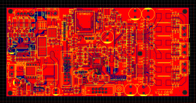
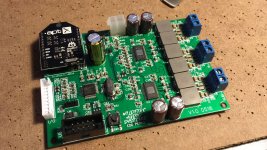
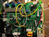
Photos include a couple of the prototypes of the 'split' battery management and amp/DSP boards (which after a lot of bodge wires are working really well) and a screenshot of the integrated layout. The prototype boards in the images are using a TinySine APT-X bluetooth receiver, but this has now been changed to using a CSR module on the board.
Cheers!
Edd
So I thought I'd share a project i've been working on because I feel that you guys may have opinions and comments which might make me realise i've wasted many months of my life! I've been a great fan of making my own portable speaker systems over the years but I have always found the market offerings for the amplifiers, bluetooth modules and DSPs either too low a quality or not integrated/controllable enough.
For one example the Sure JAB Boards seem great on paper, but after implementing them i've been left with odd bluetooth clicks and pops, bad gain structuring and difficulty controlling them in more than just a basic way. Also the provided indicator LEDs are crap for various reasons. There are many other systems I have tried and can report similar findings.
I wanted a board that can accept bluetooth (4.2/APT-x) and line in, signal process it in any way necessary and split it out to 2.1 (or 4) amplifier channels. All the while the board needs to manage its battery pack, charging and user interface (i.e Pots, LEDs).
I toyed with the idea of using TI's amplifier chips with integrated DSP, but I love the ADAU1701 & SigmaStudio and I am not aware of a DSP/Amp combo IC that has a 2.1 channel mode. For this reason my current design uses analogue input TPA3116D2s, one operating in PBTL mode. Another revision exists which outputs to 4 channels. The bluetooth is received with a CSR BTM625 module, sending audio to the DSP via an I2S bus. The bluetooth module is also designed to be fully user configureable.
Control and indicator LEDs are handled by spare GPO pins on the ADAU1701. It's stretching what this chip can do but I decided that including a microcontroller which could instruct the DSP could cause too many programming issues for the end user. Keeping all the programming in Sigmastudio's visual interface was a design goal.
The system is designed for a 4S LiPo battery, and can plug straight into any RC style battery via its balance connector. Off the shelf battery management boards (BMS) always seem to under and/or over charge the cells so I wanted to manage that on my board as well to keep things simple and safe. I have two board versions, one with an external BMS and charge controller and one with it integrated. The charge controller is robust and takes 19-28VDC.
I really like the idea of somebody picking up one of these boards, an appropriate battery, a few speakers and that it essentially all the electronic hardware that is required to build a great boom box with everything down to the turn on beep customisable. I suppose I am posting this here now as I have been working on this a long time and I wanted to see if you guys think i'm barking up the wrong tree. Is this something you would use?
Photos include a couple of the prototypes of the 'split' battery management and amp/DSP boards (which after a lot of bodge wires are working really well) and a screenshot of the integrated layout. The prototype boards in the images are using a TinySine APT-X bluetooth receiver, but this has now been changed to using a CSR module on the board.
Cheers!
Edd
Attachments
Thanks for the suggestions, I think I agree on the inductors. These ones were chosen as I can source them for pennies rather than pounds (for an equivalent part made by CoilCraft). This choice was made mainly in an exercise of keeping the cost of the finished boards low.
Being an electronic service engineer by trade I know of the problems that can arise from twisting solder joints on terminals, but this is something I've only witnessed on single sided PCBs. These double sided boards should be fine and spacing the terminals as they are keeps the tracks chunky and even.
Being an electronic service engineer by trade I know of the problems that can arise from twisting solder joints on terminals, but this is something I've only witnessed on single sided PCBs. These double sided boards should be fine and spacing the terminals as they are keeps the tracks chunky and even.
I will look to releasing the schematics soon - they are spread over about 7 pages though and are a little cumbersome.
The only measuring device I have access to is a HP3580A at the moment, which is not the most modern device! I am looking into investing into an alternative soon, any suggestions?
The only measuring device I have access to is a HP3580A at the moment, which is not the most modern device! I am looking into investing into an alternative soon, any suggestions?
Based on features alone, I'd be happy to buy a few of these.
I'd have the following applications:
- Boomboxes (obviously)
- Running my PA system in remote areas - the drivers are high efficiency, so it'd actually go pretty loud.
- Possibly home HiFi if the numbers work well. A pair of those would be good for a tri-amped system.
I don't frequent this side of the forum much, but if a group buy goes ahead I'd like my name to be on that list.
This is a clear step up from the usual amp boards you can get from China. The inclusion of configurable DSP (rather than just a 2nd order filter) makes it really worthwhile. I'd expect these to sell really well if you wanted to go that way.
Chris
Yes, an unexpensive USB-soundcard linked to your PC and ARTA software does the trick.I am looking into investing into an alternative soon, any suggestions?
Thanks for your kind words and support all.
Chris661 - this was the intention, to get all of the features that you need onto one board and surpass the quality of the Chinese amplifiers.
lutkeveld - I haven't really considered going open source yet, this thing needs a lot of tidying up yet! BTW I have been admiring your designs recently - you have some good ideas going on with the latest board i've spotted you're working on.
So, the headers are:
P1, USBi programming for the DSP. (Baldin) For programming you can use either the FreeUSBi which is an adapter for the cheap CY7C68013A MINI BOARD, or the complete programmer that Sure Electronics sell.
P3, Main I/O for connecting the aux, LEDs, volume pot etc.
SPI Bluetooth, bluetooth programming with a CSR-USB SPI
J2 is the balance lead connector of the LiPo pack, then P3 is the connector for the high current battery wires.
I don't think the layout is optimal yet. Work in progress.
Battery management ICs are expensive, so i've chosen Chinese chips which so far are working well. BM3451 (BMS) and CN3722 (Charge controller). I am now working on a 'soft' power switch via a mosfet as the boards capacitance is causing arching on switches.
Thanks for your kind words and support all.
Chris661 - this was the intention, to get all of the features that you need onto one board and surpass the quality of the Chinese amplifiers.
Looks like you're well on your way.
As I said in my last post, if you do move to a production run, put my name down.
Chris
Will do Chris. I am picking this project up after being on the other side of the planet for 3 months so its finally picking up speed again. I will aim to have the next prototype ready for Feb then we will see how things are looking!
Things to do before then:
Reduce most 0805 components to 0603.
Finalise board layout.
Cost optimise BOM.
Things to do before then:
Reduce most 0805 components to 0603.
Finalise board layout.
Cost optimise BOM.
I meant open-source more so that people can jump in and help with schematic/layout but I do not know if you want to go open-source with this.
If you want you can send me a DM with schematic and layout and I will have a look, might save you some revisions
For the expensive BMS: the BQ77915 and BQ24650 is a great combo that does not break the bank. Definitely on my to-do list. But great that you found a chinese alternative.
Have you got the line-in of the BTM625 working yet? I am working on a PCB with the BTM625 but I can not get it to work for now.
Guerilla, the BTM625 does support APTX and is specified in my design.
lutkeveld, it sounds like you share my frustration with battery management! Do you have an application schematic of your TI BMS chips you could share?
In my design the line in of the BTM625 is not in use. The ADAU1701 has better ADCs so they are used instead. Once i've finished tidying up the schems i'll DM you
EDIT: I wasn't aware there was an actual APTX HD now... Im not aware of a module I could implement to add this right now. Besides, APTX sounds pretty good to me for the moment!
Last edited:
BMS Update
Just posting to let you all know i'm still working on this as and when I can and a few changes have been made recently. I have decided to split out the battery management and DSP/amp functions to separate boards, just to make the system more flexible.
Part of this increase of flexibility is going to include making the second TPA amp chip configurable as either mono (PBTL) or stereo, so the amp board can be used as 4 channel or 2.1, routing the audio appropriately from the DSP. The challenge here is keeping the board small with 4 lots of LC reconstruction filters.
The battery management board is designed to be completely user configurable, 3/4/5 cells of LiPo with user programmable charge current and discharge limit (Max 15A). Here is the board so far, prototypes will be in the post soon:
- Status
- This old topic is closed. If you want to reopen this topic, contact a moderator using the "Report Post" button.
- Home
- Amplifiers
- Class D
- 2.1 DSP Amp born of frustration