Hi there
I am encountering stability issues with this current-boosted LM337 regulator:
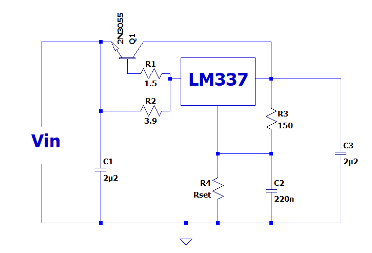
It wants to oscillate, unlike it positive counterpart.
I have tried the usual tricks, explored various values of stopper resistors, but to no avail: there is always a current value in the range (0 to 5A) that makes it oscillate.
I do not particularly like this topology, but in my case it is convenient, and I would like to have it working.
The capacitors are all MLCC, and I have tried much higher values, with some success, but intractable residual instabilities still remain.
I have found two methods to completely cure them: making C3 >100µF, low esr, or inserting a well-damped 12µH inductor into the emitter of Q1, but I would prefer softer methods (the regulator is used in my betameter, and the cap would need to be bipolar to accommodate both polarities).
Any ideas?
I am encountering stability issues with this current-boosted LM337 regulator:
It wants to oscillate, unlike it positive counterpart.
I have tried the usual tricks, explored various values of stopper resistors, but to no avail: there is always a current value in the range (0 to 5A) that makes it oscillate.
I do not particularly like this topology, but in my case it is convenient, and I would like to have it working.
The capacitors are all MLCC, and I have tried much higher values, with some success, but intractable residual instabilities still remain.
I have found two methods to completely cure them: making C3 >100µF, low esr, or inserting a well-damped 12µH inductor into the emitter of Q1, but I would prefer softer methods (the regulator is used in my betameter, and the cap would need to be bipolar to accommodate both polarities).
Any ideas?
Attachments

Nothing, except it is a 3A partWhats wrong with the LT1033?
That's one of the first things I tried, but reality and sim do not agree: the least worst value is 0, and any addition degrades the situation very quickly.add some esr to c3?
I went to more than 10µ for the caps, but it wasn't sufficient; 100µ does it though (low esr).
R1 is not even required; I added it just in case, but it changes practically nothing
Yes, the cap values on output (and adjust pin) need to be significantly larger - its is good practice for the 337 even without the booster circuit; it really helps noise and stability - its noted in one of walt Jung's papers - IIRC, the one on current sources part 2.
(Also see this on the LM337 Simple Voltage Regulators Part 1: Noise - [English])
I agree with RickTH:
Don't use a low-esr on the LM337 output, def not 2u2 mlcc! - that'd need a few ohms in series, c 3.3-4.7, to approach stability with the regs' apparent output inductance. A cheap, big dumb not-special electrolytic is the way, 100-220uf in round numbers. And 10uF or more for C2. HTH
Edit: to be clear - I don't see the booster circuit being the issue here - it's the LM337.
Last edited:
Yes, I agree that the 337 is the problem.
The booster circuit is an irregular use of the regulator (although it appears in the applications), but for the positive version it does work most of the time.
The 337 is more difficult, and you don't see application examples with a booster (AFAIK).
In my case, minimizing the esr (can't go below zero, unfortunately) and maximizing the capacitance (to 10µF, the highest I have as MLCC) almost made it stable (it depended on temperature).
Using a low-esr, 220µ cap at the output solved the problem completely, but as I said, the context was complicated (would have required a BP cap).
In the end, I settled for the 12µH emitter inductor, damped with 2R7 //. It is very compact, perfectly bipolar and stable, thus problem solved for me
Good fix : )
But the easier one - do not use low-esr caps with these kind of regulators!
Here is why:
Using 3-pin regulators off-piste: part 3
Added to which - one more thing:
When you add this classic external-transistor 'booster' circuit you might, like me, look at the series R (R2 on the first post above) at the input to the LM3x7, and think' if I add capacitance to 0v after that - that would add RC decoupling on the input of the regulator IC. Is that useful for lower noise ..?'
The answer again is NO. I tried this recently for a bits-box 'bench PSU' lash-up. The result is you get a really good blocking-oscillator. It's no use at all, don't do it ; ) (a few moment's thought and a few equations will show you why)
Hope this helps someone!
Once again: the first fix I tried was to progressively add resistance to the capacitors -it made things worse, and the higher the resistance, the worse-Good fix : )
But the easier one - do not use low-esr caps with these kind of regulators!
I know that it is not the way it should be, but you cannot argue with reality.
Even a regular E-cap, having a normal esr didn't work: I had to use a good, low-esr type
I know that it shouldn't be done, but I tried it anyway, out of desperation, to leave no stone unturned, and it did make things worse thus no surprise thereAdded to which - one more thing:
When you add this classic external-transistor 'booster' circuit you might, like me, look at the series R (R2 on the first post above) at the input to the LM3x7, and think' if I add capacitance to 0v after that - that would add RC decoupling on the input of the regulator IC. Is that useful for lower noise ..?'
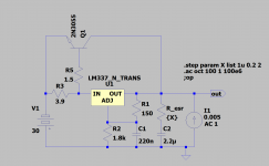
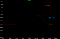
My theory is that the additional transistor adds unexpected loop gain to the 337, which is already borderline regarding stability.Hey Elvee -- I have sim'd this with various combo's of DC Load, and capacitor ESR. It is indeed a stickier wicket than the LM317!
Even with a fix, curiosity still wants to know why.
Jack
Adding the emitter inductor acts as a compensation, lowering the HF gain.
It would be difficult to achieve the same results with capacitors, because typically you would add a capacitor between the base and the collector, but this would ruin the HF PSRR
Note that I had to use a "good" inductor: my first trial was with a 5-hole ferrite bead, but the result was disastrous, worse than the original problem.
I switched to an air coil, and it almost eliminated the problem by itself. Adding a // resistor made it perfect, but of course the air coil was unpractical.
In the end, I found a small 12µH wound on a metal-powder toroid which gave the same results, without the bulk and the stray fields and was properly damped by the same 2R7.
The ferrite had the same nominal value, but probably saturated during the current peaks (the average current was 5A max, but during the relaxation oscillations, the peaks were probably significantly higher)
- Status
- This old topic is closed. If you want to reopen this topic, contact a moderator using the "Report Post" button.
- Home
- Amplifiers
- Power Supplies
- Taming a boosted negative regulator