Portable Analog PEQ - High to Low impedance conversion

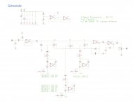
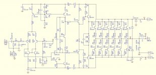
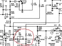
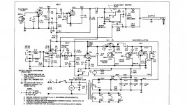
Suppose you own the following Parametric EQ circuit (I don't :crazy:). It was designed for electric instruments, but you want to use it with a low impedance (line level) source.

3-band parametriq EQ (slim) - PCB
3-band parametriq EQ (slim) – PCB – TH custom effects

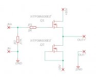
Would it suffice replacing the 1M input resistor and 1M pots for, say, 10k values, to have it 'properly' working? Or the whole chain of caps/resistor values (or even opamps) would have to be revised? Or, for instance, additional parts to be added?

Personally, I need a portable PEQ for experimenting with on-the-fly recordings..., Q control is very important for me. However, the closest I've found (analog and portable) are designs for guitars or high imp. instruments. Their size and 9v battery power supply are convenient, but I need low impedance to plug it to the line out of any mic preamp.

If this works, I thought it could be also interesting to use as a small PEQ stage between my DAC and active speakers. This might sound like non-sense or simplistic, but that simple is my knowledge here and I'm curious about what experienced listeners think about it. I have never used an analog PEQ before indeed, only digital filters.

If there are also any comments on the quality of the circuit itself, please let me know. Maybe the whole experiment would turn out in disappointment because of noise/phase shift or bandwidth control the design offers.

Thanks!
Domingo

Attachments

  • 3-band-parameq_V1.0.jpg
    3-band-parameq_V1.0.jpg
    690.2 KB · Views: 113

CRC for multichannel power with one transformer

I got used to multi-channel sound, made aleph 3 x 5 channels, did not apply filters at first, but I'm going to reorganize the power supply, the question is whether it is appropriate to make a CRC filter where the last RC go to each channel separately, distributing the load from the total C 2x100KuF => 5x (2x0.5ohm+2x33KuF=> amp.))? or it is still better to combine them .

myaplifer — ImgBB

FAOW thoughts a la B1

I am a bit late on the entire FAOW game, but this is something I have been thinking about for a while

We do not have power jfets, but perhaps we can make this work with depletion mosfets?

I will order a few parts soon to play with. I just wanted some feedback because I am probably missing something. Maybe an output cap to allow for more loose matching?

attachment.php

Attachments

  • faow-b1.jpg
    faow-b1.jpg
    27.6 KB · Views: 252

Favorite Threads and Posts in "Solid State"

Favorite Threads and Posts in this Forum

This permanent thread is a place for links to threads or posts in this particular forum that are useful and/or exemplify the best of DIY Audio.

This is so others- especially newer members can find them. Feel free to post with these links and a brief comment on what the thread discusses Occasionally the moderators will consolidate them into fewer posts.

JL Audio 450/4 noise issue

Hi, everybody. Thanks for the add! I have a JL Audio 450/4 amp that has an issue that I'm hoping is easy to fix.

I've connected it to three different input sources with varying results:

1. Receiver on boat - audible noise whine without engine running (didn't start engine), frequency hunting and varying without obvious reason.
2. Iphone plugged directly in using battery in garage for power - very minimal hum, sounded great otherwise. All 4 channels producing powerful, clean sound. Hum slightly louder in right channels.
3. Iphone playing through JL Audio bluetooth adapter (that is normally playing through my garage's system with absolutely no noise, hum etc). Adapter is powered by 12 VDC power converter (cheap plug in adapter from Amazon). Very loud static comes through all channels. No noise plays through garage receiver but similar noise is present as I plug RCA's into the back of that receiver before outer ground terminals contact. Once ground terminal contacts, noise stops. Not the case on this amp. Noise is continuous on all channels.

Similar results when in 2 or 4 channel input mode.

I know next to nothing about diagnosing these amps, but it seems that the issue is in the input stage somewhere. It also seems that there is a missing ground connection or something to that effect. I assumed that the outer (ground?) connections for the RCA terminals would have some continuity between each other so I measured them, but they measure a consistent 3 megaohms between each other. The output RCA's measure approximately 0.5 ohms between outer terminals. I measured a couple of PPI amps I have laying around and they measured 20 ohms between outer terminals.

I did my best to search this forum and I saw mention of confirming that the input board was fully seated, so I pulled the amp apart, lifted and replaced the board with no change. When the board was out, I noticed some of the coating on the bottom of the board that covers the RCA input solder joints was a bit crusty, so I scraped the loose stuff off with my fingernail and brushed it away, thinking it may be somehow creating a bridge between the inner and outer RCA terminal connections. No change in function.

I apologize for my improper terminology and I'm here to learn. Thanks in advance for any advice you guys have! Thanks! Mike

Rotel RA-970BX problems

Hey guys, new to the forum. I'm glad to have found it.

I just picked my rotel RA-970bx from my local stereo repair shop.
They told me they could not fix it and its to old to get parts.
It needs a new input selector, and a new power button and power cord.
The power cord should be easy, the power button is just sticky so not a big deal at this point.
The problem I'm having is, the sound is cutting in and out more so at low volume levels, and the sound quality is just horrible.
This integrated amp is in mint condition to look at, I've had since new and love the sound I get from it.
Could it be fixed and could this be something I could do myself, I'm handy but never tried to fix something like this before.
I was also thinking about replacing it with another rotel from that same vintage, but I was also told from the same repair shop to stay away from used rotel gear from the 1990's because I would be asking for more problems of the same.

I like the rotel sound with my B&W 610i speakers, I was thinking a preamp power amp from the mid to late 90's would be a perfect fit for me if I can't fix what I have.
Can anyone point me in the right direction, all suggestions are welcome.
Thanks for any and all help

Tube use? 24->300V large cap charger with 300V 150mA reg

24V dc to 300V dc capacitor charger with regulation (300V at 150mA at 78% efficiency): https://www.analog.com/media/en/technical-documentation/data-sheets/lt3751.pdf

So this not only can cope with managing inrush on a 2+mF 300V cap, it can also then regulate current output too. User configurable max charging limit too..

Seems it may be of interest to tube users.. now if only there was a larger regulated 500mA-1A version.

There’s also a coilcraft transformer specifically for this..

Whole house audio

Hi...
I need your help if you can , i am doing a whole house audio in the cheapest way possible about 16 zones , i want to buy this Diy board

WIFI Bluetooth 5.0 Audio Receiver DIY Smart Adapter Board Module with AirPlay DLNA Multiroom HDMI ARC Optical AUX USB I2S|Wireless Adapter| - AliExpress

And i need to Conection to it as follows:
1 - optical input ( from tv )
2 - aux in ( from any device )
3 - aux out ( to amp )
4 - usb input ( audio source )
5 - volume , source select , source playing indication, mute , in shot term control of the board from nextion touch screen 7” to be mounted on the wall connected to the whole house through ESP32 with home assistance.
I really appreciate if you can help me , i have zero experience in all of this .
Thank you for your support
I await your reply
Best Regards

https://ae03.alicdn.com/kf/H5ab5c5db1d0346e09f34f2921201d3c6F.jpg
https://ae03.alicdn.com/kf/H6af5c14820de410a9652414c8defa38dE.jpg
https://ae01.alicdn.com/kf/H06720e2aa15f43f2aaf80fe07bc76790U.jpg?width=800&height=800&hash= https://ae01.alicdn.com/kf/Hc7d64be9e6254401ad937f7b8abbe5c0M.jpg?width=800&height=1690&hash=2490

Is there a DIY Pultec (stereo) eqp-1a tone control?

Hello all,


I recently saw a demo of an old school Pultec eqp-1a and was wowed by it. It reminded me of a fully adjustable loudness contour that you find on many stereos...but on steroids! However, I almost choked on my cup of water when I saw what this thing is going for on Ebay. Further, it is a mono unit, not stereo. Given that it only has three tubes in it, I would figure that one could build the thing for around $300. So that is what I am asking. Is there a kit for this tone control out there? If not has someone built something like it?

Heatsink info

Hello, I have s a general question about heat sinks. I do hvac work for a living and I came across some old abandoned/dead vfd’s (variable frequent drives) and the light went off in my head. These things use decent size heat sinks to cool the scr’s which have good amounts of current flowing through them. I’ve pictured them below. Can these be used did a custom chassis build? The backs of all are flat and obviously a couple of them need to be further disassembled but before I waste anymore time, I thought I would ask. Thank you guys in advance.

Attachments

  • A8E4C677-6592-4400-93D0-F8F5B7530280.jpg
    A8E4C677-6592-4400-93D0-F8F5B7530280.jpg
    1,008.5 KB · Views: 203
  • B96B60CC-7BE9-4678-A118-CBDA51B4DBAF.jpg
    B96B60CC-7BE9-4678-A118-CBDA51B4DBAF.jpg
    1 MB · Views: 203
  • 2C896D67-6DAF-4877-BF14-036BFEE10C3A.jpg
    2C896D67-6DAF-4877-BF14-036BFEE10C3A.jpg
    1 MB · Views: 195
  • BEF55887-44F2-455B-8DD4-5275AFEE0405.jpg
    BEF55887-44F2-455B-8DD4-5275AFEE0405.jpg
    1 MB · Views: 191
  • D4CA44CA-5ABF-4464-9A3D-8D249963D612.jpg
    D4CA44CA-5ABF-4464-9A3D-8D249963D612.jpg
    1,008.6 KB · Views: 199

Help with small horn design

Hi all,

I have Wharfedale TwinX 12X boxes which are 12" coaxial and I want to do away with coaxial drivers as I struggle to get replacement drivers and they are very expensive.

I want to go for a normal 12" + 1" configuration. I want to mount to a 1" compression on one of the vents which has a diameter of 80mm. I might use sheet metal or fibre glass for the HF horn. Please assist with tiny horn design for 1" compression driver, that can be mount on a 80mm round hole.

HDMI Audio Extractor no sound

Hi.

I want to connect my PS4 to PC speakers.
I have an eBay HDMI Audio Extractor - 1.5M HDMI AUDIO EXTRACTOR 4K HD CONVERTER INDEPENDENT STEREO OPTICAL FILL | eBay

When I connect my PS4 in HDMI In port, my PC monitor in HDMI Out port and my speakers in 3.5mm jack, I get picture, but no sound.

Then I noticed, when I connect only PS4 and 3.5mm jack but do not connect monitor, I get sound. But, as soon I connect my monitor, the sound disappears.

I can even see, that as soon I connect PC monitor, the red light from SPDIF port goes dark.

Am I being stupid and do not understand how to connect extractor, or it is just not working?

Thank you.

Connecting More Outdoor Speakers

Hi all, forgive the neophyte question and I apologize if this has been answered elsewhere. I might just not know the right terms to search to find the answer.

I'm currently am running a pair of Definitive AW6500 outdoor speakers off of my Dennon receiver. I love the speakers and am changing the configuration of my yard such that I'd like to add another pair to cover more area. The speakers are 8 ohm. How do I go about adding another pair without damaging the receiver?

input cap location

I recently bought a 45 set amp which has caps installed directly to the backside of the rca inputs. I am looking to replace the caps with something nicer and was just wondering if the placement of the caps matters or not. It would be much easier to fit them somewhere between the inputs and pots. Does placement along the input wiring matter as long as it stays before the pots?

Elekit 8200R questions

Dear diy gentlemen's I am now also a proud owner of the elekit 8200R and I have a few questions about this. 1) what difference is there exactly in the sound when I replace the standard coupling capacitor with Mundorf? 2) And what kind of sound can I expect in terms of improvement when replacing the default opt ​​to Lundahl Opt? Sorry for the bad english this is google translation Best regards:Buizenbak.

PUI HD microphones - why is only the largest one flat?

Looking at this product brief, the 4, 5.8, 6 and 8 mm models all have a nasty HF peak whereas the 9.7 mm is pretty flat.

New Audio Solutions | HD Series Microphones

I seem to remember that you want a small cross-section for flat response under 0° incidence. For these models, this does not seem to be the case.

I wonder about the role of how they are constructed. The 8 mm easily has the nastiest peak at 15 dB, and overall, there is no correlation with size. Even the pin version of the 5.8 mm fares better than the surface mount version of the same size?!?

Does anyone know which type of FET is used? The S/N is unrivalled except for some of the newer Primo microphones which incidentially have the sam S/N for each size class.

New Member - Hello

Greetings,

Just joined today. Long time audio addict and retired. Not going to bore you with background and interest only to say in my quest to DIY, diyAudio kept coming up.

I will say for now that I have projects going on with several amplifiers (including tube), tuners, turntables that are not DIY.

I have accumulated several good speakers including Zenith 49CZ924 drivers. My goal would be to get an education and ideas for putting together a good pair of speakers. Hopefully someone can point me in the right direction as a peruse through the forums. I would also like to someday build two mono tube amps.

Look forward to meeting you. I'm easy going.

Cheers!
Rick

Rebuilt Hafler DH-200 input boards

I have two (2) Hafler Dh-200 input boards which I rebuilt using parts from qua co. Both boards were stripped of all parts EXCEPT the wound coil, then all resistors, capacitors, diodes and transistors were replaced. I bought the kit of parts on e-bay from qua co who seems to know a lot about these.
One board has two MOSFET'S and wiring, the other has all four MOSFET'S and thermistor and heat sink.
I thought I would see if anyone here is interested before I put them on e-bay. I already have two DH-200's already which I rebuilt and improved the power sully on, don't need these any more. Gave up on amplifier number three.
PM me best offer, please be reasonable.
Here are pics of the first one.

Attachments

  • IMG_0072.JPG
    IMG_0072.JPG
    156.2 KB · Views: 295
  • IMG_0073.JPG
    IMG_0073.JPG
    150.4 KB · Views: 291
  • IMG_0074.JPG
    IMG_0074.JPG
    122.1 KB · Views: 290

Turntable Bearing heated

HI,

Has anyone attempted to make a platter bearing with tight allowance and heated the bearing to have prompt and steady RPM regardless the room temperature?.

I was looking for a Ceramic small heater but the temperature range is too big for this application. I think a temp around 30 degree Celsius would be ok.

I read that someone did with fish tank heater, but the normal 5 or 8 watt heater tubular are too long for my application.

If someone has done it, can you kindly provide some information?

Thank you and best regards

Adelmo

Intermittent static on one channel of Acurus A250

I recently bought an Acurus A250 amplifier. The seller disclosed that the one channel had an issue with intermittent loud static on the right hand channel. What he did not disclosed was that extensive work has been done to try to cure the problem with no success. I can see that the output transistors on the faulty channel were replaced, all the solder joins were reflowed and the psu caps were replaced. The boards are simple enough that I could swop out all the components until the problem disappears but I am hoping that one of the amplifiers gurus on Diyaudio could assist to point out components that I should try first. Any help assistance would be gratefully accpeted.

Attachments

  • 20210511_080943_resized.jpg
    20210511_080943_resized.jpg
    744.5 KB · Views: 240
  • 20210511_081012_resized.jpg
    20210511_081012_resized.jpg
    825.7 KB · Views: 233
  • hfe_acurus_a200x3_a250_schematic-1.jpg
    hfe_acurus_a200x3_a250_schematic-1.jpg
    625.6 KB · Views: 227

Nutube build

Hi Everyone, Now that I built an F5 I know everything, right? I have decided to build a Korg Nutube B1. I have the board and nutube, and I am finding the rest of the parts. I am going to build my own chassis. I want to make one or two modifications to the design.

1) I would like to make it less likely to mess up my speakers if somebody turns it on or off with the amp on. Am I correct in believing I would be able to use the soft start board offered on the diyaudio store for that purpose?

2) I want to build it with 3 input channels instead of the 2 that are in the design and build guide. I believe I would have to use a potentiometer with 3 0r 4 channels instead of 2 if I do that change. I am in the planning and part collecting phase of the build. Any help with planning this modification or with reasons for or against it will be helpful to me.

Thanks

Adau1467 DSP Board (China)

I sell a new DSP Board with adau1467, see pictures attached.

€99 + shipping

Bought it here (14th oct 20):
Neue ADAU1467 entwicklung board 83 routinen, freie konfiguration 20 eingang und ausgang|Luft-Reinigungsapparat Teile| - AliExpress

Lots of documentation and examples for sigma studio are included, also a schematic.
Docs are partly chinese or google-translated. Board Pins and connections are extensively labled.

I tested once, it works. DSP programmable over USBi-connection (SPI).

To be honest, it is nice, but has the onboard ad1938 codec (the 3.5 audio jacks, 2in, 4out)
fixed to 48khz, all SPI-Pins of the ad1938 soldered to ground.

Thats why i don't want to keep it.

I made the price a bit lower because of this.


The other connections (SPDIF, lots of i2s) should work flawlessly up to 192khz.

.

Attachments

  • IMG_20201110_100511.jpg
    IMG_20201110_100511.jpg
    688.1 KB · Views: 255
  • IMG_20201110_100557.jpg
    IMG_20201110_100557.jpg
    1,009 KB · Views: 217

Pre-Amp - LM1036 + NE5532 Clipping and Distorted Bass

Hi guys,

I bought this pre-amp.
LM1036 NE5532 Stereo Preamp Preamplifier Treble Bass Tone Board DIY Amplifier | eBay

I found no schematic, It's not clear what 'Power Seat' is.
I found the DC input has no polarity (Center pin can be positive/negative).

I tested it with 12V 1.5 A power supply (SMPS and Linear PS). The sound is good, detailed and clear but when I crank up the volume and bass control more than halfway the bass starts to clip and distorted.

Anyone has experience with this pre amp board? Is this clipping normal? Is there something I can fix/mod to get rid of the clipping? Thanks. your help would be very much appreciated.

Desktop speaker with Markaudio Alpair 5.2

I had them on the shelf already quite some time, had some ideas in my head for even longer, but the past easter weekend I finally got to building the follow up to my Desktop Speaker with the 1st gen Alpair 5.

Let's begin with the end result:

attachment.php


more info in the follwing posts.


*) And yes, it's the gen2 version, that is still "current" with dealers here in Europe

Attachments

  • PP2021 klaar.jpg
    PP2021 klaar.jpg
    303.9 KB · Views: 1,776

Onkyo DX-120 CD player restoration

New project: Onkyo DX-120 CD player from 1986. What intrigues me about this unit is the TAOHS laser pickup (made by Olympus?) and the use of several Yamaha IC chips for servo control, data decoding & recovery, & DAC.

I recently dug it out of my storage unit. Current status:

It powers on.
Tray opens and closes.
The carriage drive is functional.
The machine performs a focus search but fails to detect the presence of a disc.

Next I measured IR light intensity. It was 150 mW. Service manual says it should be >250mW. Another post on diyAudio suggested 300mW for this particular optical pickup (TAOHS series). I raised the light output in tiny increments until I reached about 275mW.

At this point it displays the TOC information rapidly and will play a CD which is in perfect condition. However it won’t play through the damaged areas of “less-than-perfect” discs that have scratches. These same discs plays without interruption in other machines.

The service manual describes a “skew adjustment screw” and states “adjust it for best eye pattern.” Adjusting this revealed that the adjustment must be all the way at one end to get the best eye pattern.

I am able to get a decent looking RF signal eye pattern. The service manual shows 3V P-P and that’s what I’m getting.

However I don’t think the carriage is moving smoothly enough. It sometimes seems “sticky.” I’ll have more on this after I post photos of the carriage assembly. Some sections of it look very well-made and precise, but some other parts in it look really crude to my eye.

I’d like to get this Onkyo DX-120 into a condition where it will play most of my discs.

-EB

Hello from Amsterdam, the pandemic pushed me to this...

hello everyone.

I am new to this community and new to tinkering with audio electronics.
In the middle of the pandemic, I was looking for a hobby to do at home and things got out of hand. I now own a number of broken NAD pre-amps and amps. Here is the list

NAD 1020 series 20

The phono output was not working in the right channel. Decided to recap and now the right channel is super faint and scratches when the volume is almost 3/4 up. (this goes with the 2040 below)

NAD 3020 series 20

This is my total failure, it was working find decided to recap and now it is all over the place,

NAD 2040

Have not tested it yet

NAD 214

Was working fine then the right channel started fading in and out (not sure if it is this or the pre-amp)

NAD 106

Need to test but it started having a very low noise in the transformer so it may be this and not the 214.

The question is what forum should I post questions for these units?
Thank you

Hopefully, you all can help me become better at this. :wave:

DIY 3-way Monitor/Listening Build

Hi diyAudio community

This is my first thread, I've read a lot of other threads on here but have finally worked up the courage to begin my journey into building my first set of DIY 3-way monitor/listening speakers. Firstly, I'm from Cape Town, South Africa so I'm looking to import parts from Europe somewhere most probably since nobody stocks what I'm looking for here.

Here are some details about what I'm thinking of building:
- Near- / Midfield
- Integrated amp for each side
- Some sort of audio management
- 3-way speaker layout
- tweeter: ??? amt?
- mids: ??? 4"?
- woofers: ??? 10"
- compact in size
- sealed enclosure - more accurate?
- hits at least 30hz - bonus if its lower


Amplifier

I've been researching and it seems the best option for me is an integrated amp for each side, the Hypex FusionAmp FA253 (Hypex Electronics B.V.).

- integrated class-d amps on each side
- integrated dsp and dac on each side
- Power (4Ω) 2x 250Wrms + 1x 100Wrms or
- Power (8Ω) 2x 150Wrms + 1x 100Wrms
- quite a few input sources
- remote control extra which could be great

I feel like if I buy these they should supply enough power to the drivers, although I could get by with the FA 123 (2x125W + 100W Tweeter) depending on the drivers.

I found out that kjfaudio.com stocks these for a decent price. So will most likely get from them. Wondering what the import costs would be on those since I'm in SA?


Enclosure

I'm planning on building it with composites in the future but will probably start with mdf to prototype the build. The future build out of composites will be some layers strategically sandwiched together utilising the vacuum bagging process. I've got an idea about how to do the layering, but it will take some time to get the shape right before I start that. The size of the box will be determined by the parameters of the drivers I decide to go with of course, but I'm still left wondering what sort of size I should go for since the box is sealed.

I feel like the amps are going to have to be mounted in their own sealed section in the rear of the speaker cabinets so I will have to plan to have some extra space available for that. Anything else I should keep in mind?


Drivers

Now this is the part I'm struggling with. I'm looking at possibly buying drivers from europe-audio.com, anyone have any experience with them? They seem to have a large collection of drivers available which is great, but also not great because of so much choice.


Tweeters:

I'd like to use an amt for the tweeter on each side since they are better at reproducing more accurately with lower distortion, if I've heard correctly. I know there are some nice ones available but I don't have as much capital as I'd like since I'm having to import.

On europe-audio.com they have a few varieties of AMTs - (Tweeters Ribbon | Europe audio). They all seem to be Fountek. Possibly the NeoX3.0?


Mids:

Now it gets more difficult. I think I'd like to pair the tweeters with some 4" midranges. But I'm open to suggestions for other sizes. Currently I think these will give me the most clarity I'm looking for and can also go slightly lower to crossover with the woofer better.

Europe-audio.com have the Scan-Speak Illuminator 4'', from the reviews I've read it sounds like it could work well.


Woofers:

I'm looking forward to using a 10" woofer to hit the low. Hopefully it can reach to 20hz but I feel like that may not be easily possible and most probably draw too much power so I'm thinking of aiming for 30hz. I think that is a bit more realistic considering.

Europe-audio.com has a nice selection of Scan-Speak and Seas speaker drivers, but I'm unsure how to narrow my search here.

The Seas L26RFX/P H1209 could be a good option I think, will this pair nicely with the Scan-Speak Illuminator 4"?

What about the Scan-Speak 26W/4867T00? Would this be better to pair with the Illuminator since they are both Scan-Speak?


Closing thoughts

I know this is going to be a journey, but I'm keen to get started. I'd like to keep this thread updated as I progress through the build so I'll try take lots of photos and document the process.

Please feel free to answer my questions or ask me some. I'm new to this but I feel like I know enough to get started, theoretically anyways.

I2S DAC for CM108B

Hello Friend,


I'm looking for an I2S DAC chip that can be used with the Cmedia CM108b (USB to I2S).

So far I've been looking at TI DACs because I'd like >2V Vrms output level. However it seems in "H/W control mode" (meaning no dedicated microcontroller), the CM108b's masterclock (x256) does not match what the DACs can handle (x64). Do you have any tips for a readily available DAC IC that is better than the CM108b's internal one?

Thank you very much.

NAD 1020 lost volume in one channel after recap

New to the forum, and new to the hobby.

I started working on a Nad 1020 (that I hope to pair with a nad 2040) I changed most of the caps and now I have lost volume in one channel (right) and when the volume is 3/4 up (on the right channel alone) I hear a scratch (distortion) left channel works perfectly.

My soldering skills are not great and I wonder if I did something there or if during the recap the volume got somehow damage.

What should I do next?
Grazie

Spitting noise - any thoughts?

Playing a CD this evening and after an hour of moderate volume, simple music the system started making loud high frequency cracking or spitting noises, mostly but not exclusively, on the right channel. The music was double bass and vocal, so no high frequency sound to speak of.

I immediately shut it off to protect everything rather than messing about. It has never done anything like this before. I don’t know if the sustained bowing of the double bass had heated up certain components more than usual and caused something to overheat, however, the heat sinks on the amp were only mildly warm.

Before I dive in to the amp, if anyone has any thoughts of what might cause these spitting noises, I should be very grateful. For example, could the ageing MOSFETS be complaining perhaps?

Musical Fidelity A3.2 CD player, fully recapped 12 months ago with Elna Silmic II caps. Fitted with Burson Audio V6 Vivid opamps 6 months ago.
Musical Fidelity A308 integrated amp, serviced and levels set 3 years ago. Recapped with DNM smoothing caps and Elna Silmic II 10 months ago.
Monitor Audio Gold GR20, replaced crossovers with Mundorf caps and inductors and Mills 12W resistors. All components of higher than original ratings and point to point wired.

It doesn't help that there are no manuals available for MF gear, of course.

Thanks for your wisdom in advance

Alternative to the SAA7220 for TDA1541 dac's

Background... My cousin discovered way back in the late 1980's a better option to the Philips SAA7220 digital filter. I recently got permission from him to disclose the information for DIY use. So as my cousin has no presence here I give him full credit for the information contained in this thread. Thank you Mr. Joel Henry of Apple Valley, Minnesota. 😉 The device in question is the NPC SM5814 4X oversampling digital filter. This chip has a special feature. It has I2S output capability. The only caveat is this filter needs 2's complement, MSB first right justified data on the input. Back in the day we used glue logic on the input to use it in Philips based CD players. This was not ideal however. Today we have another option. Most people build stand alone D/A converters. That being the case we can now cleanly apply this part with substantial gains in clarity and fidelity with the various flavors of the TDA1541, TDA1541A etc. I have 3 stand alone D/A converters built up running this digital filter. So I can say with certainty that it works and works well. Suggested configuration..... WM8804 (input receiver output set to 2's complement, MSB first, right justified data). NPC SM5814 set for I2S output. TDA1541 (Red Baron or other board). I/V, I have a preference for the no negative feedback types such as the AD844 in triple stack, Pedja Rojic's DDNF Discrete diamond no feedback I/V with buffer modification or the ADEL2020 in a standard feedback configuration. Filter preference is a second order transformer based filter using a Cinemag, Edcor or other line input transformer. I will attach the hard to find datasheet...

Raspberry + Tidal

Hi everybody,
I was using a Rasp4b with moOde streaming from Tidal till last week.
From last week Tidal is not giving access to moOde anymore (from what I understood).
So I'm looking for a way to stream music directly from Tidal from the raspberry: I don't want to use another "source" (mobile phone) using Tidal Connect and streaming in this way to the raspberry.


So I was looking for a version of rasp OS that could run a Tidal app or something similar... As anyone got any idea?
Thanks

Crim

Resolute Audio RA2500/RA0105

The intent of this thread is to just shed a little light on the Resolute Audio replacement for the Tripath TDA2500/TA0105.

After paying a premium $180 I finally have a replacement for my dead TDA2500. I was very anxious to finally see what this board is made of. Well, it's made of a Tripath TCA2002 processor IC and two IX6R11S6 MOSFET drivers.

If I kill this one at least I might be able to resurrect it for a fraction of the cost of a new board. 41hz.com sells TC2001 IC's which I believe can be used as a replacement (still trying to find the difference between the TC2001 and TCA2002), and the IX6R11S6 can be purchased from digikey.

Behold.....

34efho3.jpg

t5owoy.jpg

Behringer Xenyx1002FX repair (SOLVED)

I'm posting this for future reference as I found no repair info online.

circuit board is p0572 pcb904080revc

I had one dead main output on this mixer.

There is a heat sink on the side connected to 3 voltage regulators: +12V -12V and 5V. If you have all voltages there should be no need, but I flipped the heat sink around to be able to access the circuit board underneath.

My problem was a bad solder joint in the opamps around the master fader. IC22 is directly before the master fader, IC23 is directly after the master fader. Outputs of IC23 is connected directly to R204 which is a quad 3k9 resistor pack.

I remelted the solder joints on all these parts as well as the master fader and gave the fader a good squirt of tuner 600 and it was back in business. Hopefully this will save a couple of these units from the trash pile.

EDIT: Also, gain adjustment on ch1 did not work. It was the actual gain potmeter. 5kC05 is printed on the board, so so it should be a 5k reverse logaritmic.

AEG rectifier

I have here from old parts an AEG Rundfunk-Gleichrichter, (broadcasting-rectifier) coded B 250 C 125 L

B should be silicium 250 the voltage, 125 the mA's i think.

It is a black aluminium tube about 11 cm long, and 27mm diameter. Wires come out of bottom like a lytic cap. It has 4 terminals, 2 yellow (AC) and a red (+) and blue (minus)

Has anyone some info about this rectifier. How does it work (silicium, or mercury??) Might use it for a rectifier in a single 6922 line amplifier.

Thanks

Bypassing L-Pad Pots Leak 3090

Hey all,

I've gotten myself lost in another speaker project so I'm coming to you chaps for help! I'm trying to replace or bypass the volume pots on my Leak 3090s. One of the existing pots completely failed, and I never feel the need to adjust them.

Here's where I'm getting confused. All three drivers in the top cab have a variable L-Pad pot, with an additional 4.7ohm resistor in parallel (I'm not sure what this is for).

On the pots, the LMR and HMR both max out at +2db, and the tweeter goes to 0db. This would indicate to me that at the 0 point on the pot, the L-Pad on the tweeter should measure almost no resistance, and the other two should be making a 2db pad as they are the exact same component. However, upon measuring the pots I got roughly 1.7ohms on the serial, and 30hms on the parallel on all three. By my calculation that's a 2db L-Pad. Perhaps a stop was set on the tweeter pad?

It's possible I'm over complicating this but it would be nice to have some confirmation on my logic. My current plant is to replace the L-Pad pots with 2db fixed L-pads, but I'm still unsure of what to do about the 4.7ohm resistor in parallel as I don't understand it's purpose. I've attached a schematic I received from a kind member on here, and I've highlighted the bit in question. I have already recapped the rest of the crossover and replaced all the wiring with Van Damme Blue.

Many thanks,
Blindmelon7

Attachments

  • Schematic Page 1 Highlighted.jpg
    Schematic Page 1 Highlighted.jpg
    231.5 KB · Views: 60

SUMO Polaris II Questions

Hi,
I have enjoyed my Polaris II for many years. I recently had to refresh the solder joints at one of the inputs.

Most of the SUMO threads here are well-aged, so I'm starting a new one in the hopes we can get some contemporary replies.

I have two questions:
1. I have the corrected amp schematic courtesy of this forum. Does anyone have the power supply schematic?

2. Until I opened the amp up, I assumed the LEDs (CR12, 13, 14 and 15) were Vee and Vdd indicators, as I used to see neon lamps used as B+ supply indicators on some old tube equipment. Looking at the schematic, they are driven by Q8 and Q9 which I *think* are part of the servo circuit. But I'm not sure...anyone know what their function is?

Thanks in advance

Echoplex EP-2 Regeneration Issue

Hi Folks,

Wondering if you have any insights on my Echoplex problem. This is an early-version EP-2, no Sound-On-Sound. The issue is that it won't go into regeneration. The "Echo Repeat" circuit feeding V2B looks admirably simple, and I doubt the issue is a bad 1 Meg resistor Any other places you'd check?

Many thanks!

Attachments

  • EP-2_Detail.jpg
    EP-2_Detail.jpg
    245.5 KB · Views: 139
  • EP-2 Complete.jpg
    EP-2 Complete.jpg
    708.5 KB · Views: 126

Which Pass Amp to build F5/F6/Or anything else?

I have been thinking about building one and only one Pass's Class-A amplifier. I always used BJT based Class-AB for serious builds and recently Chip-Amps and never built a Class-A.

What would be a good Pass Class-A that I should build to experience that? I was looking at F5 and F6, or are there any better ones with readily available components (from Mouser or Digikey)?


Thanks for your suggestions!

Want to build the F5 turbo v2

Hello, I want to build the F5 turbo v2 to drive my HE6SE (waiting delivery from HIFIMAN), but I have only experience in soldering cables for headphones. I’m very careful and precise in my work, but I’m still unsure about jumping on this DIY build as my first project.

Reason I want to build the F5 turbo is that I already have a Topping A90 and readings from forums make me think I need a speaker amplifier. The A90 delivers 4.8W to 50 Ohm, and following the chart listed on DIY-Audio-Heaven and recommendations of up to 16W to 50 Ohm from other forums, I think the 50W from F5 turbo v2 to reach 8W to 50 Ohm is bare minimum for reaching a Profound improvement in sound quality.

Some people say 10W (8 Ohm) Class A (First watt F1) works like magic with the HE6SE but I don’t understand why? 10W according to DIY-AUDIO-HEAVEN is 1.6W in 50 Ohm.

English is not my first language so please ask if anything is not making sense.

EDIT: Maybe posted this in the wrong forum section? If so please move in moderators

The Perfect ESL?

Has anyone constructed electrostatic speakers based on what's described here?

http://wireesl.weebly.com/uploads/2/4/9/7/24970733/segmented_esl_theory.pdf

The paper relates to a slim floor-to-ceiling wideband ESL design using the concept of a resistive "transmission line", in order to get a near-ideal polar/frequency response, whilst presenting a manageable amplifier load.

Particularly of interest would be the possibility of using a resistive coating on the stators to implement the design.

OPT Wiring question

Hello again,
I'm wiring up the OPTs for the SSE, and my chosen transformers' wire colors don't correspond with those on George's wiring diagrams. I have the Toroidy TTG-EL34SE

The output side is clearly labeled, so that's no question.
But the input side is a source of confusion. The UL tap is clearly labeled, and then there's two wires labeled A and +U. Is "A" the anode? And +U is...?

Each OPT connector on the board has three contacts. I can see that UL goes to contact 2 if connected, but I'm not sure which wires should connect to contacts 1 and 3. Which goes to contact 1? A or +U?

Restore Hallicrafters S-85 Shortwave Radio

I have a Hallicrafters S-85 shortwave radio that I would like to restore. It's a radio I grew up with so the restoration is more for personal reasons rather than value or a collection. Are there resources out there for parts and service? An internet search turns up some places that deal with old radios but since it's not something I have dealt with before I would value some recomendations.

Need owners manual for AES SE-1 300b power amp

Greetings all. Might anyone have a copy of the owners manual for the Audio Electronic Supply SE-1 300b power amp? I have not been able to track one down and Cary has not yet responded to my email to them.

Alternatively, if anyone else out there owns one of these amps please reply to this thread - I have a few simple questions I'd really like some help with.

Best regards,

Markus

adding preamp outputs to Sanyo Plus 55

I am thinking of adding preouts to my Sanyo Plus 55 receiver. I used to be a licensed repair tech, so I can read a schematic and build from one.

I am not an engineer and would like someone to look at this.

I identified, on the schematic, what I believe are the outputs on the pre section and the inputs on the amp section. Circled in red.

I think this is the input to the amp section:
attachment.php

I think this is the output from the preamp section:
attachment.php

Rebuilding 1972 Marantz Receiver

QUESTION:

As I'm going though this receiver, I want to replace
all the old 51 year old ceramic caps with either new
films, or Micas, or new C0Gs.

I haven't done anything with the AM or FM boards, yet
and probably don't want to replace those tuning ceramics.

However for the other boards, like tone amp, etc, is there a
reason to keep the old ceramics in there? They get noisy with age,
they become micophonic etc. I assume even the 51 year old NP0s
on the phono board get that way also.

I'm upgrading Transistors, diodes (and caps) as I come across them
board by board for new modern replacements.

This receiver is for my little girl who loves music.

Cheers,

Billie Eilish Bad Guy stress-test for turntables?

Hi all,
this is for me more out of curiosity than anything else, as I don’t really see it as a “problem”.

You might be familiar with the first song on Billie Eilish last album and its extreme bass. It sounds great to me from the vinyl but it really feels that it is driving the cartridge to its limit. The thing is that in my system, while sounding good, it generates some clicks, like if the record had a scratch, but it isn’t that because they are not regular and not always at the same time if you play the track twice.

I am really curious to know what is causing that. Is the stylus generating too much signal or something like that? Has anyone observed something similar in this or any other song with lots of bass?

I use a Pro-Ject X1 with a Pick it S2 MM cartridge (which I believe is an Ortofon red) with a Trigon Vanguard II/Volcano III phono stage

Matsushita AN136B low noise high gain audio preamp (vintage)

Some NOS items came up on a local auction site, I wasn't able to find a datasheet so I have no idea if they'd be any good for a phono preamp or similar.

I understand they're equivalent to NTE1053 but the specs I could find on that IC were also scant.

They come in a round can with 10 pins.

If anyone can shed light or share any information, I'd be interested. TIA.

Problem using OPA134 model in LTSpice

Hi to all Spice experts.

I'm a relative novice and trying to work out how to use audio opamps that are not in the standard distribution (e.g. 5532/4, 071/2, OPA134). My version of LTSpice on Mac OSX is 17.0.33 which I believe is current.

I have found a model for OPA134 on the net, I believe from the manufacturers site. This is attached. I have loaded the .lib file and created a symbol from the related .asy file, so I can now add the opamp from the [autogenerated] folder in the F2 dialogue box.

Everything OK until I run and then I get this error message:

Unknown subcircuit called in: xu1 0 n001 v+ v- n007 opa134​

I'm assuming this is an issue within the model file? Any advice welcome.

M

Attachments

Projects by fanatics, for fanatics
Get answers and advice for everyone wanting to learn the art of audio.
Join the Community
507,753
Members
7,886,730
Messages

Filter

Forum Statistics

Threads
406,158
Messages
7,886,730
Members
507,753
Latest member
ayodej