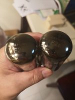
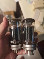
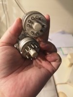
Vintage 3Watt Tube

Hello Solder slingers

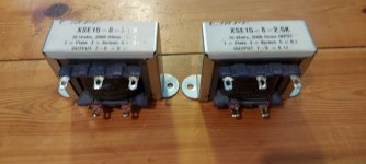
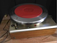
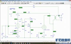
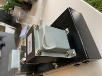
I have a 3 Watt single-ended power amplifier made by Packard/Bell. It was scavenged from a small console stereo. I no longer have the preamp section or the speakers. But as a stand-alone amp using EL84 tubes it can power a full range pair of speakers. I'd like to turn this into a HeadPhone amp with volume control and a single input! I know very little about amplifiers, but I thought some guidance could be found here in Tubes and Valves. I do have a schematic someplace from a long-ago curiosity search. Help, suggestions, directions?

Thanks, kingfisher

Sherwood AD-2220 CP Please Help!!

Hi guys i have some real troubling problems with my sherwood amp, other than its 100 years old and cant afford a schematic .. i realy need 2 photos / resistor codes if someone could help me out that would be soo greatly appreciated.

i need a good quality photo of the protection board ( it has a 5112100 stamp on it its small & square, fits in your palm the other is onthe left side of the power supply (right near the relay) there is a couple of little green resistors i need to see the codes for they, same with the protect board i'll note their names

i would love to hear this amplifier, the only way that will happen is if i can repair it, i have no problem fixing things but the resistors are completely fried and i cant read their bands! please help!!

the codes are (POWER/AMP BOARD) R401R & R401L (Their located near the 2 10 ohm 2 watt resistors (grey colour risen off the board)

and R329R & R329L (PROTECT BOARD)

I have replaced the 2 left and right R330 resistors with 1 watt resistors, even if someone has a service manual i would realy love if i could have some help please please helpp!!

Options for bass in dipole system

I'm looking into adding two subs, maybe sealed or H-frame OB, and maybe run the H OB further into bass, and wanted to gain insight from the experienced.

My system: two 12" Rythmik servo subs in DIY sealed boxes below 65Hz in mono, and per side: one 18" Faital 18HP1010 baffleless dipole on a swing from 65 to 275Hz, twin 8" from 275Hz to 1.8kHz (bottom 8" on U baffle to reach to 275Hz) and AMT above. Active 4-way, digital xo and room correction.

Happy with Rythmik sealed subs and thought about adding two more to get a distributed bass array. And I came across GR Research/Rythmik OB servo subs in H or W baffle, getting great comments, that can be xo up to 200 or 250Hz. Looking at their model with dual 12" per sub.

And this has me thinking about these options:
  1. add two sealed Rythmiks to the existing two and play 20-65Hz.
  2. add two GR Research H baffles to the two sealed and play all of them 20-65Hz. I wonder if mixing sealed with dipole bass, despite both being servo-driven, would be detrimental.
  3. add two GR Research H baffles and play them 20-200Hz with the two sealed reinforcing 20-65Hz. Getting DBA below 65Hz. 2x12" have less surface than a 18", probably noticeable from 65 to 100Hz or so, but the GR have servo so allegedly more controlled/articulated than the 18".
  4. add two sealed Rythmiks to the existing two and play 20-65Hz, and later add two GR Research doing 65-200Hz with a shallower H or just a panel. This might in turn drive me to replace the 18" with a 12" dipole which eventually would allow to raise the xo to the mids from 275Hz to 400Hz or so.

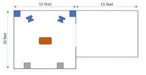
The room: it's the living room, with little flexibility as to placement. It's 30x16x2.4 feet high, divided into two sections (dining and living room) by a wide sliding door. Current subs and speakers shown in blue, and the listening seat.
room.jpg

The grey squares show where the two new sealed subs would go, or where the sealed subs would go should I get OB subs. OB subs could be placed somewhat away from the corners, but baffle would likely be about 30" from front wall.

What are your thoughts about OB vs sealed bass below 65Hz?
And baffleless 18" vs twin servo 12" on a baffle in 65 to 200Hz region?

Thanks in advance!

speakerparts.co - CNC flatpacks / custom + public designs

Anyone interested in a build but put off by lack of CNC or wood skills, we provide CNC flatpacks for any simple or medium complexity builds.

The website is in works (Custom CNC cut DIY speaker cabinet flatpacks baffles MDF Baltic Birch – SpeakerParts) but you can message me for ordering. Welcoming trial users. 🙂 We are in the KC area so shipping should be reasonable all over the US.

Transistor Ft as function of Vce?

To build the perfect amplifier that we all want - we need to know how transistor Ft varies with Vce. So we can optimise.

Bob Cordell's book (p22) says Ft droop at lower Vce at hi current, with a "Vce ... as little as 5V ... current ... several amperes" in an example.
The On semiconductor datasheet for the MJL4281A (fig.9) has the reverse, with better Ft at Vce=5 than Vce=10 for the entire current range shown (.1A to 10A)
A net search didn't show much accessible research. I even overworked my brain with the original Gummel_Poon paper in the Bell Systems Journal.😱 I suspect there's several different effects that interact in a complicated way. Any pointers to more information or an explanation?
Or it could just be a mistake in the datasheet.
Edit: Which is what it is.

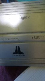
help with jl audio e1200

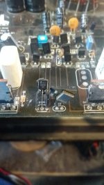
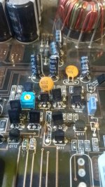
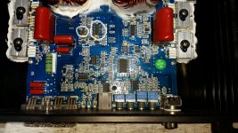
When connecting the amplifier it does not turn on and consumes more than 7 amperes without load, disconnect the loads one by one and detect a possible short, all the power section transitors were disconnected, and the equipment turns on, a mosfet transistor was discovered in short j111, The detail is that when you reconnect the power transsitors and stop turning on the equipment, when making some voltage measurements it is detected that in the gate terminal of the section that is fed from the positive +35 v of the mosfet there are 15 volts, some suggestion.

Attachments

  • WhatsApp Image 2021-08-02 at 9.18.31 PM (1).jpeg
    WhatsApp Image 2021-08-02 at 9.18.31 PM (1).jpeg
    63.2 KB · Views: 78
  • WhatsApp Image 2021-08-02 at 9.18.31 PM (3).jpeg
    WhatsApp Image 2021-08-02 at 9.18.31 PM (3).jpeg
    85.8 KB · Views: 87
  • WhatsApp Image 2021-08-02 at 9.18.31 PM (2).jpeg
    WhatsApp Image 2021-08-02 at 9.18.31 PM (2).jpeg
    116 KB · Views: 80

TPA3122D2N Solderless Breadboard

So I'm working on a project that's fairly complex overall with many components and one component is a power amplifier stage after a PCM5102 DAC. I'm basically retrofitting an old radio with entirely new "guts". I'll write more about it later, it's quite an adventure, but one component is a power amp stage. I've not built an amp before but I was aiming for Class-D mainly because they run cool and so don't need a heatsink.

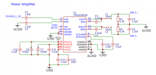
For this project, I'm trying to go all-through hole. The radio isn't huge so I don't need to worry about getting loads of power from the amplifier. I found the TPA3122D2N, but I'm worried it's actually not powerful enough, so I wanted to breadboard it to test it with the speakers in the radio before I build (and pay for) a complex PCB. I'm leveraging the existing transformer which provides around 13.5V DC once rectified and smoothed.

I bought all the components needed (basically the list from the TPA3122D2N datasheet) and started building. But I can't generally get the thing to make any sound. This is probably because it's on a solderless breadboard. I did get it to make sound once(!) but then I turned it off and when I powered it up again, nothing. All I get is a rhythmic clicking at about 4Hz.

My schematic is attached, although I've since switched from BTL to SE (by providing L/R on the inputs and splitting the outputs accordingly) since my input signal will be SE from the DAC.

This is tearing my hair out! Can anyone make some suggestions, or should I give up with the solderless breadboard?

Attachments

  • Schematic_Bose Upferb_2021-05-15.png
    Schematic_Bose Upferb_2021-05-15.png
    29.7 KB · Views: 473

Akai AM2450 Volume in one channel fades

recently picked up an Akai AM2450 and has issue of audio in either channel fading out and sounds distorted while it does. When this happens its only to one channel and can be either.

turning up the volume temporarily fixes it.

I thought it'd simply be dirty volume pot and or dirty contacts in the speaker relay. However the issue persists.

oh and wow what a relay! the thing should have a clear casing to show off it's internals lol

The caps look original, unless they were replaced long ago and in entirety.

The volume pot had a ton of oil residue, it has a particularly open design. but I don't think the issue is either of those components. its been cleaned.

Particularly because the issue can be one channel or the other.

all other adjustments sound and work fine; balance, bass, treble. switches sound fine too; input, Loudness, Mono / Stereo, A/B speaker.

It has watt meters, which work when speaker switch is off...however when the fade out issue happens
it can be seen in the watt meter...it slowly decreases in magnitude.

The pots for bias look rather suspect / are completely open design.

Any ideas?

SSE sounding muddy. Could I have something connected wrong?

Hi all. I built an SSE awhile back, and I'm finally getting some free time to listen to it on the regular. Right away, I've found that it doesn't sound very good. Muddy. Almost muffled sound. I've tried other amps with the same speakers and they sound clear as a bell, so I suspect maybe something is up with my SSE.

Mine is built in the standard configuration. It has motor cap and choke. Tubes are EL34, and the output transformers are Toroidy TTG-EL34SE.

To those who might be willing to help me figure this out: What information do you need from me? Would photographs help? Any other part numbers you need? I'd love to get this sorted, as I think this amp has lots of potential. So I'm happy to provide any additional info.

Thanks in advance, Tubelab gang!

The Output stage querries !!!

Gentlemen,

Iam looking to build an amplifier for myself with IPs(considering spooky, ComSuMo, Wolverine, GLA surviour) & OPs on different board so that I can interchange the IPs only incase required.

Iam looking for 2 options:

1. Lateral Mosfet stage OPS

2. BJT OPs stage

As a DIY starter want suggestion on OPs:
a. If I consider Slewmaster OPs with drivers changes to Lateral mosfets(not sure if anyone has tried this way) what could be effected in terms of sonics ?
b. Has anyone tried https://www.synaesthesia.ca/OP-stage.html ?? Or any better suggestion with L-Mosfet OPs is requested.

Thank in Advance,
Suman

Idss tests of LSK489 and LSJ689

A few months ago I ordered a few JFets from an internet site that had limited supply. I only ordered (4) LSK489 and (4) LSJ689. Results for Idss of the LSJ689 had a wider range than I expected (and the high Idss get noticably warm). There is no way to order grades like other parts such as LSK170, LSJ74, LSK389.
So if you need 2 pairs, I guess the safest thing to do is order 4 😕. I'm not sure changing ccs or source degeneration resistors is a better way to make up for good matching..
There's another supplier of Linear Systems that has many more parts in stock. Maybe better luck with them? Could others post results if you have them available?

LSK489: 3.41mA (A), 5.46mA (B), 6.04mA (B), 7.80mA (B)
LSJ689: 6.47mA (A), 7.10mA (B), 11.76mA (B-C), 14.56mA(C)

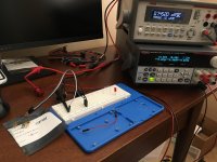
Attached picture of test setup, Vgs=0V, Vds=10V, measured using ammeter V+ to Vd for Ntype and Vd to V- for Ptype.
Also attached spice sim for all grades as reference.

Attachments

Which of these ICs can be swapped out with the OPA2134?

There is/was a shop in Idaho that was doing upgrades to the DBX 3BX series one dynamic range expander. One of the things they did was swap out ICs for a much better OPA2134. It was a drop in replacement, no mods to the surrounding circuit needed. Other than that I can’t get any other information. This is what is in the unit:

10 - LF351N
8 - LF353N
10 - RC4558P
1 - LM301N
3 - unknown, the markings have been removed.

My best guess is the RC4558P. Could it be possible to replace the LF351N and LF353N with the OPA134 and OPA2134? I really wish I could get more info on this.

Is link a schematic, but the only one I can find isnt the best quality and needs to be zoomed in on. The images I post get fairly degraded.


Thank you,
Dan

Pioneer BOFU 4 sale

found a pair of the Pioneer BOFU drivers in the office today. thought they were gone.

anyway, is anyone interested in buying these? the surrounds are good. they were installed in a pair of the hedlund cabinets & then returned to the original shipping box from parts-express.

$50 + shipping. probably via fedex or ups.

if any are interested, i'll post some pics.

thanks.

Mutual coupling question

I found this in some ElectroVoice product literature:

"When two speaker systems are placed side by side, the woofer cones “mutually couple,” causing the two systems to act as one system with twice the effective cone area at very-low frequencies, giving an additional 3-dB increase in maximum acoustic output. Mutual coupling will occur when the frequency is such that the center-to-center distance between the two woofer manifolds is less than about one-half wavelength."

I have two identical subwoofer cabinets, placed side by side in a corner of my listening room. They are crossed over actively at 90 Hz. I've been trying to get my head around the mutual coupling thing as it applies to these boxes. Here are the numbers:

Center-to-center distance = 44.7675 cm

Estimated Speed of Sound = 34500 cm per second

Frequency = Speed of Sound / Wavelength

For Wavelength = 89.535 cm, Frequency = 34500 / 89.535 = 385.3 Hz

What I get from this is that mutual coupling only occurs above 385.3 Hz. I wouldn't call these "very-low frequencies"! What am I missing here?

EDIT: I did a search here and now I'm even more confised....

I found this formula:

Fo = c/(d*sqrt👎)

Where

"c" is the speed of sound in the air in metres per second (normally 343 is used, but can vary slightly according to air temperature and humidity).

"d" is the distance in metres between the two speakers

"n" is the number of sources.

Fo = 343 / ( .447675 * 1.4142 ) = 541.77 Hz

Help?

Thanks,

dooper

Help please - Sub sounds *blah*

I've have a Stryke Audio HE-15 in a 22" cube with two 18" PR's. My box (purchased pre-made) is roughly half of the box pictured (actual interior dimensions are around 22"x22"x22") in the following link - thanks "greg", it's hard to find these specs nowadays.

link for subwoofer

I have a Mackie m2600 to power it (I bought this used). Here is a link for the specs:

link for mackie

I have the Stryke's 3ohm dual voice coils wired in a series.

My problem with this is the output.

With the mackie in bridged mono mode, I do not think I am getting adequate output. The amp shows that it is giving it all she's got (the front led's light up to the "clip" level), but the sub is barely moving...maybe 3/4 inch excursion. And the sound level is certainly lower the my SA 12 in a 1ft^3 sealed box with a 500w digital amplifier.

The mackie has the low pass filters off and the crossover at 120hz.

What's going on here? I have access to a much smaller amp (around 150w) and I only have rudimentary tools (a Radioshack db meter and multi-meter).

Am I expecting to much?

If not, what steps should I take to test the driver, passive radiators, box design, and amplifier? - I'm gonna assume that the box design is OK at least.

Any help would be much appreciated!

Thank you,
Chris

Anyone done a custom PCB for a small low fi BT/AMP before?

i've been watching a few youtube videos (like probably most of you), which were actually non audio related and noticed how many people seem to be getting PCB's and custom chips made, which made me think of has anyone done a small bt amp for a lowfi build?

i've bought a few CSR8645 Amplifier Boards and other variants of them (QCC3008) and due to the size find it difficult to firstly solder onto, but trying to cram it, plus a battery and a boost coverter all into a tiny build.

So my question would be, has anyone done a custom build, if yes, would it be hard to do for somebody who doesnt know how (but keen to learn) and how hard would it be to integrate something like a TP4056/7 1S BMS and a boost coverter (3.7 to 5v) etc?

I have a few builds which are basically 3d printed 500ml beer cans with a downward firing 2inch full range and i want to use the amp as it has the ability to be modified through the BT chip and use custom EQ settings (and it is small).

example

Csr8635 dual 5w bluetooth 4.0 /4.1 amplifier board audio bluetooth 4.1 receiver module with call function Sale - Banggood.com

Info on mercury rectifier DCG1000-01

I have some mercury rectifiers that I have not planned on using. But I am tinkering with the idea of a 'show off' amp just for demonstrating the fascinating side of tubes, and tube glow is a part of that.

One set I thought of using is a pair of Philips DCG/1000-01. But I cannot find any data on filament voltage and current.

I do find the DCG4/1000, this has 2.5V/4.8A filaments. So can I assume DCG/1000-01 is 2.5V but only 1A?

Any one here know?

As for using mercury rectifiers. I know some of the risks, probably not all, I know one must apply heater power long before HT (at least 1 minute?). Is there a tell tale way of knowing when one of these are bad, and even if they may catastrophically self destruct?

If I want to dispose of them, where do I drop them off? I guess the local dump has 'dangerous goods' section and will send them to where they belong. I dont intend on selling them, just because I dont like poison going to who knows where...
Or am I over reacting?

thnx for comments

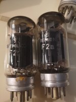
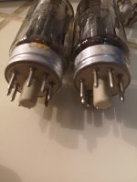
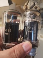
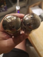
Siemens F2A tubes

4 pieces of F2A tubes for sale $400usd OBO , one of the pair is used for a few tens of hours for an experiment. The other pair is plugged in for tests, and then stored. Selling as it is, no returns. Pm me to check shipping cost to your location. Will ship from Singapore.

Attachments

  • IMG_20210802_095622_resized_20210802_100340341.jpg
    IMG_20210802_095622_resized_20210802_100340341.jpg
    612.3 KB · Views: 232
  • IMG_20210802_095628_resized_20210802_100337694.jpg
    IMG_20210802_095628_resized_20210802_100337694.jpg
    428.2 KB · Views: 232
  • IMG_20210802_095643_resized_20210802_100338546.jpg
    IMG_20210802_095643_resized_20210802_100338546.jpg
    644.3 KB · Views: 231
  • IMG_20210802_095814_resized_20210802_100338856.jpg
    IMG_20210802_095814_resized_20210802_100338856.jpg
    495.6 KB · Views: 223
  • IMG_20210802_095835_resized_20210802_100339480.jpg
    IMG_20210802_095835_resized_20210802_100339480.jpg
    420.1 KB · Views: 221
  • IMG_20210802_095841_resized_20210802_100339825.jpg
    IMG_20210802_095841_resized_20210802_100339825.jpg
    508.9 KB · Views: 95
  • IMG_20210802_095852_resized_20210802_100340087.jpg
    IMG_20210802_095852_resized_20210802_100340087.jpg
    478.9 KB · Views: 119

WAV playing - Advices for beginner

Bit-Perfect playing WAVs - Advices for beginner

I'm just taking the first steps to get good stereo music from my WAVs through an entry-level system made up of a digital interface, a (digital) stereo amp and a pair of passive speakers running Windows 7 x64: no audio NAS, no media streaming, no music server intended.

I'm passionate and experienced about listening to music, both live and played within the walls of a room, but through my PC I have almost no experience at all and even if my PC-based system is currently an entry-level one I would like to (understand and to) get the max possible quality sound from, so I started reading and still reading articles and discussions, but now I'm a bit confused and would like to receive authoritative confirmations or even denials about some basic principles.

Running a capable software player is the Bit-Perfect playback applicable to WAV files?
If so, how do you get it?

I'm just trying 2 players that I like: Album Player (free) which I really like and JRiver Media Center (commercial) which I like enough, both with strengths and weaknesses and both with the ability to use the ASIO driver supplied with my audio interface.

I think I understand that if you use ASIO driver (or WASAPI too) for the Bit-Perfect playback then both Windows mixer and volume control are just bypassed and no longer functional, but I still can't get it: is the above true also playing WAV files?

Definitely, how to get theoretically and practically the best possible sound quality from my system playing WAV files under Windows 7?

Many thanks in advance for any appreciated addressing.

ONIX Power Amplifier Model OA701 (OA-701) Schematic wanted

This amp works fine, but there is a hot spot on the amplifier PCB. The reason are two very hot transistors from front-end in a E-line envelope like this outline:
https://www.diodes.com/assets/Datasheets/ZTX652.pdf

For check the reason in detail I want to have a service manual or at least the schematic diagram.

Under
History | ONIX - Hi-End audio products from england since 1979
there isn't to find a download portal for pdf schematics and service manuals.

Who can upload the schematic?

More URLs:
https://www.audiovintage.fr/leforum/viewtopic.php?t=37135 (images)
Onix Audio - Wikipedia

Emilar ew15-8a (altec style woofer) .?

Hey

Plan to build a old school large 2-way, perhaps petite Onken, or altec 612, or similar. Found a pair of Fostex H320 wooden horns (tips for a 1” cd going low would be nice, or if building an adapter to 1.4” is more clever, would probably work).

There are some old Emilar ew15-8a 15” woofers available, together with Emilar Ec175 and upgraded Emilar crossover of 800hz.

From some old threads, it sounds like the Emilar elements are compared favourably to Altec etc., but do any of you know? Or even have data for especially the woofers? (I read fs of 21 hz, likes large cabinets, was in a 220l box).
Maybe worth a gamble? Or better keep looking for a 414 / 416 / ? (Really hard in Sweden..)

Thanks in advance 😬

What would you do if you lived forever?

What would you do if you lived 3000+ years?

Read an interesting article: assume all medical issues are solvable and nobody dies of illness or old age problems. You keep the mind and body of, say, a 30yr old, indefinitely.
How long would you live then? The surprising answer came from life insurance actuarials: about 3000 years. That is the average life expectancy in our part of the world, based on only accidents, suicide, murders, that sort of thing.

Then I though: what would I do with so much time? Build your own home, a brick a day? Spend 30 years to learn all about amp design, design the ultimate one and build it including designing and building each part? Take up a study and spend 50 years to learn all there is to learn about, say, the Roman empire including doing an in-place decade of archeological digging?
Would you jump off the roof top due to sheer boredom after a couple of centuries?

The sky would be the limit!

Jan

Halfler P230

I have a Halfler P230 amp. Even at very low volume, my speakers sound like they have bass breakup. I tried other speakers, and they do the same thing.
I checked the large power caps (10000uf 75 volts) with a VTOM. Infinite resistance. If indeed the caps are bad, would that cause this problem??? How doe the amp even work if these caps are bad?

Kairos Three-ways

I’m considering doing a build of Jeff Bagby’s Kairos 3-ways. I have built the CJD Khanspires, a Dayton RS series 3-way, and like them. I’m now interested in building something with a bit higher end drivers and a bit more exotic cabinet construction would be fun too. These will go in a 12x12 home office, so I don’t need huge output, but…

Has anyone built these, and if so what are your thoughts? Would you recommend an alternative for full-range, high quality sound smallish room?

Test results: wow/flutter & heavier mass platter

I recently purchased a mint condition 1961 Empire 208 turntable. Everything was in excellent condition, sans the belt and rubber mounts. I replaced the belt and rubber mounts. I also re-lubed the motor thrust plate, turned the thrust plate over to the fresh side and inserted a new precision ceramic ball in the motor thrust plate. The platter spindle has a steel ball bearing which needs to be replaced, but I have not done so yet.

Using the iphone RPM app to record speed and wow/flutter (I can not vouche for the accuracy of the RPM app, but its the best I have), I recorded several measurements for speed accuracy and wow/flutter. FYI: I use a Long Dog Audio LDA Quartz Regenerator power supply which keeps a steady voltage. The Long Dog Audio unit allows the platter speed to be adjusted easily with 0.01 increments. So, I was able to lock into 33.33 RPMs and it did not fluctuate during use.

Using the stock platter (aluminum which rings like a church bell), the iphone RPM app recorded a wow & flutter measurement of 0.16 - 0.18%. This range was consistent across 3 measurements.

Then, I added a 60 pound platter from a prior DIY project to the top of the stock platter. The 60 pound platter was centered within 0.001" TIR. With the added mass, the wow & flutter measured 0.06 - 0.08% (again measured 3 times). The only variable between the measurements was the platter weight.

Also of note, with the stock platter and motor off, I spun the platter and it continues to spin for a few minutes. I used a stethoscope to listen for bearing noise. None detectable. In all my years of using a stethoscope, I always detected bearing noise until today. Quite a nice feat for a stock 1961 turntable.

Then, with the 60 pound platter added to the stock platter, I once again spun the platters and used the stethoscope. Bearing noise was clearly audible. The bearing noise was cyclical which indicates that the sleeve bearing is where the noise is occurring, not the steel thrust plate. The sleeve bearing noise was likely caused by a slight imbalance in the platters weight distribution and thus would shift the bearing laterally and create the bearing noise.

So, where does this leave us:

1. 60 lbs incremental platter mass reduced wow/flutter by 50-66%.
2. Heavy platter needs to be appropriately balanced to no longer cause the sleeve bearing noise.

The 60 lbs platter is not suitable for the current setup (see photos), as it was taken from a 17" OD Gates CB500 transcription table. So, I am considering a new high mass platter and bearing.

Meanwhile, the stock papst motor purrs like a kitten, albeit with the fan noise that is inaudible at the listening position.

More to come.

Pat

Attachments

  • Screen Shot 2021-08-03 at 1.20.07 PM.jpg
    Screen Shot 2021-08-03 at 1.20.07 PM.jpg
    70.8 KB · Views: 280
  • Screen Shot 2021-08-03 at 1.20.18 PM.jpg
    Screen Shot 2021-08-03 at 1.20.18 PM.jpg
    193.9 KB · Views: 268

Looking for a data sheet for DNA Sequence Midrange

Hello,

I'm having trouble identifying the part used in the DNA Sequence for midrange reproduction.

From DNA Sequence Speakers dipole open baffle woofer high efficiency point source array midrange tweeter treble loudspeaker

"5.75 inch polypropylene sandwich cone midranges made in Denmark - possibly the best midrange driver ever made!"

I bought 25 of them a few years back, and I'm trying to build with them, but having trouble figuring out the right crossover point and enclosure arrangement.

The inductance is vanishingly low, and the transient response is very good, and the SPL is around 92dB if I recall correctly.

Thanks in advance for any help.

BK Precision 2120 gone blurry

I bought a used BK 2120 scope about 7 months ago, and its been pretty faithful actually up until this afternoon. I know how to use it and have been using it on average about an hour per day since purchase.

The trace line for both channels just today quadrupled in height. Focus cannot get the trace line as sharp as it was even just this morning. Nothing has changed at all afaik but then again dealing with old equipment. The scope still works otherwise but very annoying not seeing that sharp trace.

I opened it up but everything seems very clean inside.

Foreign object to me. There are no pots for focus fine-tune adjustment within either.

Anybody know how I might service this?

freeDSP V2.0 (ADAU1452) developement thread

If you don't feel like searching the thread..

PiDSP is on GitHub:
Sourcefiles[/QUOTE]

There is also manual:
PiDSP manual

Final(hopefully 😀) version is under way. You can watch the progress in development branch in Git repo.

I'm also pondering about having a batch of PiDSP boards profesionality made.
If you are interested, drop me a PM.


----------------------------------------------------------
----------------------------------------------------------
Hello everybody 🙂,
few weeks ago I've discovered the freedsp project and found it to be very interesting... but the ADAU1452 seems so much more potent dsp.
So I got in touch with the creators and joined the team with focus on new version with ADAU1452. I've been pondering about it for some time now, reading datasheets, researching, playing with possibilities etc.
Now it's time to open development thread and ask you about your opinion, feedback, and ideas, so we can make the next version as good as we can.


Flood of questions and ideas follows..

The general idea:
DSP, DAC, PSU - each on its own separate board, connected via wires, maybe backplane. ADC is not in my scope at this moment
PCB width 100mm - enclosures available, length 80mm(half eurocard) or 100mm, we will see.
Smaller builds could fit into extruded enclosure (hammond,fischer), bigger in rack

PSU board:
talema 70000K +- 15v for opamps and 48V(via voltage doubler) for phantom - no reason not to add it. will be useful with possible ADC board
Another transformer for digital part, maybe with double secondary - second winding for analog circuitry - PLL, DAC ref. etc.
I haven't made my mind about it yet. Any suggestions?

DAC
Stacked TRS 6,3mm - only way to fit 8ch to 100mm wide PCB, 8ch - why not 4x2ch? Big, expensive, I'd like the project to be accessible, and I like KISS principle. I've narrowed down DAC choices to following:
PCM1690 - cheap, available, even got samples somewhere...
AK4358 - comparable with PCM, number-wise
dual AK4413EQ, higher performing pin compatible alternative available AK4414EQ - really nice spec.
AK4458 - new part, isn't available yet, would be nice to use new stuff in the design though. I'll try to get samples.
Opinions (and experiences) about/with DAC chips highly welcomed. My life is too short to try everyone of them, so in the end I'll just pick one and go with it,If you have something to say about them, please do.

Why no ESS stuff? I'd like you to be able to buy all necessary parts at usual outfits (digikey,farnell,mouser...).
Yes, you can buy Sabre in single qty, no problem, but the shipping is prohibitive. And world is full of sabre dacs.

DSP board.
All IO should be brought out. Clocks on UFL connectors, others on 2.54 headers, signal/ground, signal/ground... SPDIF on BNC.
We could add MCLK input, its just a few additional parts and might be useful for some.
Number of I2s lines is limited, 4in, 4out more channels is accessible via TDM. I'm considering providing isolation on I2S lines, so you could use the board directly with BBB as a source.
Would be nice if one could plug BBB directly into the board - you even could program the dsp with it.


I believe it's enough for a first post. Opinions, advices, questions?

At this point it's just bunch of ideas, in the end it could be single board with XLR outputs.... Nothing is set yet... well probably DSP, oscillator, and LDO for PLL are set 😀 ... What I meant is if you think that single board(or XLR, or DAC XYZ) solution is better, say it and add why you think so 😉

Thanks for reading

Pitrsek


P.S.😛lease feel free to notify my about my spelling/grammar mistakes via PM.TY.
Possible to do feedback from before OPT on PP amps?

OK, long shot here. Taking FB to the VAS from the primary side of the OPT (output tube plate) is a simple matter in SE amps but is there a way to take feedback from the primary side to the VAS in a PP amp? If you take it from just one output tube it might be OK for normal signals but I am thinking that things would go completely nuts when there is an overload or even class AB operation. Reasonable assumption? Any clever tricks or just bite the bullet and buy a scope?

sherwood s 6020 CP has no audio output?

Hello! I'm trying to troubleshoot my preamp, one day it was working fine and the next day it had no sound! I'm very inexperienced with this sort of thing, and this preamp is pretty old, so google wasn't much help. I've checked the fuse, cables, and plugs, and I'm about to take it apart to clean the inside. Hoping there's a simple fix that I'm missing.

Denon AVRX5200W/6200W

Hi everyone!

Troubleshooting SMPS with output voltage fluctuation from 4.8V to 5.0V, spikes to 5.2V and back to 4.8 every 2-3 seconds.

Replaced with brand new: both optocouplers U6501/02, rectifier D6515, U6503 IC.
Primary voltage is stable 160V on C6506.
T6501 secondary side is stable AC voltage.
Diodes tested OK. Caps OK. Resistors OK.
Suspect D6524, but not sure....🙁

Any help is greatly appreciated!

Attachments

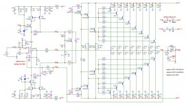
DIY amplifier: OPA 1611 + Bipolar transistor

Hello,
I am not an electronic engineer and my english is poor.
Sorry for my mistakes.

I work on this amplifier for a few month with MicroCap 12.
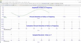
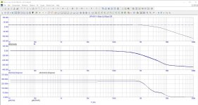
Here is the schematic, distortion with 1Watt output and phase diagram.

What is your opinion and your comments?

The power supply will be a SMPS from HYPEX + - 64V

Attachments

  • schema.jpg
    schema.jpg
    191.9 KB · Views: 691
  • Distortion-1W.jpg
    Distortion-1W.jpg
    250.1 KB · Views: 578
  • Phase.jpg
    Phase.jpg
    340.9 KB · Views: 541

Single Ended Triode Class A2 Driver Design

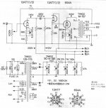
One approach to gain more output power for single ended triode amplifiers is to drive the output tube to positive grid for class A2 operation. I found two different circuits on the Internet. One uses 12AT7 and the other uses IRF610.

Can someone with more experience comments on these two approaches?

The 12AT7 seems to be biased quite low. I am not sure it can deliver 4 mA for the 6S4A tube to operate at full A2. Can I increase the bias or change the tube to something like 12AU7 or 5687?

The IRF610 for 4P1S (4P1L), on the other hand, was biased at 42 mA. It looks like good enough to drive the 4P1L. However, what are the design criteria for this MOSFET? Is IRF610 linear enough? Are there better new MOSFET for this application?

Attachments

  • 6S4A SET Class A2.jpg
    6S4A SET Class A2.jpg
    86.2 KB · Views: 1,054
  • 4P1L SET Class A2.jpg
    4P1L SET Class A2.jpg
    88.9 KB · Views: 961

Transformer took a hit

Hi everybody !


I'm new here. I didn't find a place te present myself, so i do it here.


I'm a jazz/rock and so on guitar player from Belgium, always playing on tube amps for years and years.


One of my amp took some rock and roll on the side, and the transformer took a hit. on the side. (See picture below.)


IMG_1168.jpg


My questions are the following : do you think the transformer is broken ? If not sure, do you think i can try to switch the amp on without damaging anything else than the transformer if it's broken ? (NB : the amp wasn't switched on when it took that hit and has never been switched on since.)


I don't have much of a peny to ask to a technician to repare it right now, but i still would like to play so hit singles if it's still working.


Thanks a lot in advance for your time and help.


Best everything you like,


Y.
Locating holes for tube sockets

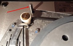
Apologies if I’m brain dead and this turns out to be a stupid question. I’m building a tube amp and need to punch holes in the metal top of the chassis for 9 pin tube sockets. How does one precisely locate the holes? I have two PCB’s with two nine pin tube sockets on each board. I can’t just lay the sockets on the metal and trace around them because the PCB’s are in the way. If I lay the sockets on the metal without the boards to locate them, then they won’t line up when attaching the sockets to the PCB’s. I’ve been pondering this for weeks and can’t envision a solution. Any help will be greatly appreciated.
GU-50 screen and suppressor grid resistors

Hi guys,


currently I'm designing a class AB2 PP amplifier working with two pairs of GU-50's. The operating point will be the one in the rightmost column at page 9 of the Telefunken EL 152 datasheet. My PSU only provides 290 Vdc for the screen grid supply, though. In order to increase efficiency by decreasing the tubes' internal plate resistance, the supressor grids will be fed from +12.6 Vdc.


The datasheet doesn't read values for the screen grid resistors and especially not for the suppressor resistors, as this isn't a very common way to go. Which resistor values would you recommend, please?


Best regards!

Whats the advantages of "Distributed Port" enlosure

Hello Folks,

I have an old and deteriorated bass reflex speaker with 8 inch driver tuned in 50hz and want to make a new enclosure

instead of make an exact copy the box i want to try some experiments

i want to try to make the same box with same tunning but instead of use a single port i want to use multiple ports like the project i saw in this old article


my question-

whats the benefits and disvantages of the distributed port enclosure compared to a single port bass reflex and why they arent so popular

Attachments

  • 1.png
    1.png
    291.1 KB · Views: 462

Need a little help with crossover design

I'm new to speaker building and I have two main questions, is it advisable to do a series parallel crossover in a 4 way speaker cabinet, and is this a good layout for my crossover in general, I'm not quite sure of the inductor layout. Also, I know the Caps aren't optimal but they were what I could afford at this time (I will be replacing them later).

Attachments

  • 0.jpg
    0.jpg
    59.4 KB · Views: 104

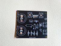
FS: some various PCB boards

Hello.

I have some pcb boards as leftovers of projects I already made.
In particular they are respectively:


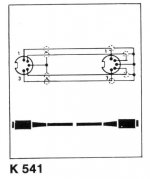
2 "DC trap" boards
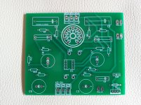
2 Boards for low voltage headphone amplifier with ECC82
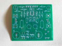
3 Boards for s.s. "Canamp clone" headphone amplifier
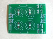
3 Dual PSU with CRC filter boards

2 LM317 (+CRC filter) boards


See attached images. If someone's interested can write here or MP.

Thanks

Attachments

  • DCtrap.jpg
    DCtrap.jpg
    557.3 KB · Views: 480
  • ECC82-ha.jpg
    ECC82-ha.jpg
    679 KB · Views: 476
  • CAclone.jpg
    CAclone.jpg
    673.6 KB · Views: 466
  • DualPSU.jpg
    DualPSU.jpg
    538.4 KB · Views: 470
  • LM317+filter.jpg
    LM317+filter.jpg
    665.6 KB · Views: 461

My built on Dual Feedback(Pre&Post) with GanFET

My Class D with GanFET & LLC

I am working on a new Class D with Ganfet. Heres what I am intending to have it in the build:

LLC Switching @ 200kHz @ full load with PC95, PQ5050 using minimal gain to reduce switching noise during light load.

Target Operating Voltage: +/- 50Vdc
1Mhz Operation.
Paralleled EPC2207
Bridged Mode
Balanced/Unbalanced input.
DC Offset protection with MosFETs & Optocoupler as switch
Protection: OTP, OCP
All connectors are PCB Mount.
Common Chokes are used in all rails.

Cant wait to have this powered up!

And I name it as TOP DOG. 😀😀😀

Attachments

  • 600w.jpg
    600w.jpg
    775.9 KB · Views: 435

Help to choose a 8" Woofer for a sealed box.

Hello,
I am currently in the market for a 8" woofer to use in a 4 ways active monitor design and looking for some advices.

It will be used in a sealed box from 80Hz to 500/650Hz with a Morel EM 1308 so i need it fairly flat that range, low distortion is also a requirement. As for the Xover itself i'm using a dsp so fine tunning isn't an issue.
I don't really care about sensitivity either as my listening spot is about 1.5m.
For the material i'd prefer (treated)paper or composites as i'm not a fan of aluminium (my current woofers are alu i know their pros and cons).
And for the price per unit i'd like to keep it under 120€/130$.

After some research i had some candidates like:
-SEAS Prestige CA22RNY SEAS H1471-08 CA22RNY - 8" Subwoofer
-Peerless 830868 Nomex Peerless by Tymphany HDS-P830869 - 8" Woofer
But i'm open to any suggestions.
Thanks in advance.

Split rail from transformer with no center tap

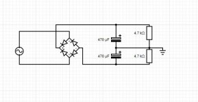
Hi Everyone,

I have a step-down toriod transformer. Really nice quality, USA made.

Its 240v to 110V, 1000W

So long as the load is equal on both rails this should work to split the rails?

the load an amp puts on the rails should be symmetric right?

please ignore part values, its just for an example.

It just seems like I'm missing something.....

Attachments

  • psu.JPG
    psu.JPG
    36.2 KB · Views: 412

The next best thing to 2SK389 / 2SJ109 ?

Just as everyone else, I am running down on my reserve of 2SK389/2SJ109s, and am looking for the best possible substitute.

The LSK389 is only available in N-JFET, and is not pin compatible. So for me no solution.

The most obvious solution is to use still available 2SK170/2SJ74 matched pairs. If you have a large pool, you can get them even better matched than the 2SK389/2SJ74 (spec at 3% match).

http://www.diyaudio.com/forums/showthread.php?postid=1689279#post1689279

But how about thermal coupling ?

You can glue them on the flat surfaces with silver epoxy, but you mess up the pin compatiblity to the duals.

So this is my solution. 😉

It has a factor of 3 more thermal contact surfaces than just gluing on the flat surface, for much improved thermal coupling, and is still small enough to fit in most applications, with a footprint of 16x8mm.

The heatsink helps to increase thermal insertia and hence thermal stability, and keep the temperature a bit lower than without.

They are not extrusions (with a minimum order of 1 ton in weight), but rather CNC wire-cut from solid. This also explains the rough surface finish, which is an added advantage as it increase surface area for heat exchange.


Merry Christmas,
Patrick

Attachments

  • dual jfet.jpg
    dual jfet.jpg
    90.3 KB · Views: 9,717

Daphile Confirmed working USB Dongles

USB WiFi dongles confirmed working


COMFAST CF - WU735P
D-Link DWA-125 Wireless N 150 USB Adapter
D-Link DWA-182 Wireless AC 1200 Dual Band Wifi USB Adapter
Edimax AC600 Wi-Fi Dual-Band Directional High Gain USB Adapter
TP-Link TL-WN722N 150Mbps High Gain Wireless USB Adapter
TP-LINK TL-WDN3200 N600 Wireless Dual-Band USB Adapter
TP-Link TL-WN725N 150Mbps Wireless N Nano USB Adapter


Direct Ethernet(PC to PC, PC to Laptop, Laptop to PC or Laptop to Laptop) settings if you can't connect via WiFi a big thanks to Indiglo for these


Daphile Settings

IP address: 10.0.0.60
Subnet mask: 255.255.255.0
Router: leave blank or 0.0.0.0
DNS servers: 1.1.1.1
Search domains: 0.0.0.0

PC Settings
IP address: 10.0.0.61
Subnet mask: 255.255.255.0
Default gateway: leave blank
DNS servers
Prefered DNS server 1.1.1.1
Alternate DNS server: 1.0.0.1


if you know of any more please leave a comment with the name and i will update the list

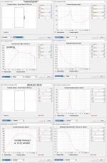
How might one set hornresp to examine the "variovent" case?

Here's a try using a Klipsch Heresy I with K22 spec woofer.

I may have not damped the port enough.

The Z peak, normally in the 65Hz region is flattened. Some peaking in the response curve shows (as does significant port output)

Attachments

  • Heresy with leaky vent.jpg
    Heresy with leaky vent.jpg
    340.6 KB · Views: 167
  • Heresy Variovent Peaking.jpg
    Heresy Variovent Peaking.jpg
    463 KB · Views: 162

Simple Speaker Protection

Hello,
Maybe some people on here will be able to answer this:
I'm looking to construct a Simple Speaker Protection Circuit using 2 x Back to Back Electrolytic Capacitors. To get reasonable Low frequency Response using a 12" 8 Ohm Driver, - (looking at commercial designs) - I assume that I will be needing a Capacitance Value of at least 2-3000 Microfarads to go in series with the Speaker Output. My Power Amplifiers run 60 volt Plus and Minus Rails, so I was thinking that 2 x 6800uF Capacitors connected Back to Back with a Voltage Rating of 40 Volts would be adequate. Somewhere else suggested using a Diode connected across each capacitor, with the + of the diode connected to the + of each capacitor would work better, to do with keeping each capacitor formed. At the moment, You cannot get Bi-Polar Caps with more than 2,200 uF at 25 Volts.
Here, I'm trying to get away from the idea of Isolation Relays or Series Forward Biassed Power Fets, because all of this can still fail. I'm looking to transfer no more than 50Watts of RMS Power, the rating of the drivers.
I'm sure that with everyone's vast experience on here, someone will know the answer! Thanks, and Kindest Regards - Telnet100

Help with 2nd Order High Pass Filter

Building speaker cabinets I can do.
Building a crossover? Uhhh....

I'm building a pro audio cabinet. But the final design was just too big. I had to downsize for portability and the trick was that I would need a high pass filter for this box.

BassBox Pro Tech Support is telling me I need this:
What you need is an active 2nd-order high-pass EQ filter with Q = 2. This should provide a +6 dB bump at the filter frequency and a 12 dB/octave roll-off below the filter frequency.

Can someone help?
Maybe sample schematics or plans I could modify for my needs.

I'm open to any guidance.

DIY Filter Reactors

I have around 100 120v:11.5v 80VA power transformers that I am trying to find a use for. They are basically factory seconds with various connector issues, etc. I also have a more or less unlimited supply of 26awg magnet wire from shaded pole fan motors of the same situation. I am thinking about cutting the "El" cores of the transformers open, 3d-printing bobbins and making "EE" core filter reactor chokes with an air gap between the "E" sections to prevent saturation because of the DC. Maybe lay a piece of fish paper between them for better insulation/separation. 26 awg isn't very thick, but I could wind several conductors in parallel for better current capacity. Does this idea have any merit at all? Is there a better way of going about it? All of this stuff is going straight into the trash if I don't snatch it up first, and I hate seeing it go to waste.


Edit: I also have a cache of microwave oven transformers as well, which I have done several things with. I've considered the same "EE core with air gap" format using them instead. They'd be huge, but I imagine the inductance would be huge as well. I'd of course cut the original windings out.

Screws that transform drywall into sound absorbers.

I just saw this article and I thought you guys might like it. It looks like a company created a special type of screw to help turn drywall into sound absorbing panels. I'm really curious how they perform. Considering the price of building a room with great acoustics this would be an amazing way to improve a room, as well as a whole house, for peanuts.

New Spring-Loaded Screw Turns Drywall Into Sound-Absorbing Panels.
Projects by fanatics, for fanatics
Get answers and advice for everyone wanting to learn the art of audio.
Join the Community
508,154
Members
7,905,079
Messages

Filter

Forum Statistics

Threads
407,018
Messages
7,905,079
Members
508,154
Latest member
Jarry@